

Proper RS485 wiring is the foundation of a stable industrial network. When executed correctly, a single pair of wires can seamlessly handle up to 32 devices (or more). If you get it wrong, you will waste days trying to find and fix phantom problems like corrupted data or complete network blackouts. The EIA/TIA standards tell you what to do, but they rarely prepare you for the real-world chaos of industrial installations.
You have verified the baud rate, matched the parity bits, and double-checked the Slave IDs. Yet, your SCADA screen is still flashing red with a barrage of Timeout and Exception Code 0B alarms. Sound familiar?
In industrial automation, transmitting Modbus RTU over RS485 remains the undisputed backbone for field sensors, PLCs, and VFDs. However, because it relies on delicate differential voltage signaling and strict timing gaps, minor physical oversights can manifest as bizarre, “ghost-like” software errors.
This guide combines foundational knowledge with the most frequent traps engineers fall into. We will walk you through fixing physical wiring myths, signal reflection, and ultimately, why generic Ethernet gateways destroy Modbus packets.
Guide Contents
Before suspecting faulty transceiver chips, hardware, or complex protocol issues, verify your baseline configuration:
Passed the sanity check but still failing? Select your exact symptom to jump directly to the engineering fix:
1. RS485 Wiring Topology: Why Daisy Chain is the Only Reliable Way
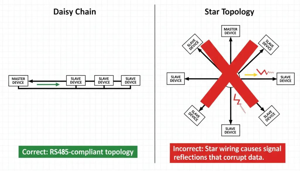
RS485 was designed for one primary wiring topology: the RS485 daisy chain (also called bus topology). Every device connects to a single main trunk line, with short drop cables (stubs) connecting each device to the trunk.
Why not star?
In a star topology, signals reflect off the end of each long branch. These reflections travel back to the main line and interfere with other signals. The longer the branch, the worse the reflection. This is physics, not opinion.
Rules for daisy chain:
- Keep stub length under 3 meters, ideally under 30 cm.
⚠️ Speed Warning: Stub tolerance drops drastically at higher baud rates. At 115200 bps, even a 0.5-meter stub can cause fatal signal reflections. Strict daisy-chaining directly through the terminals is mandatory at high speeds. - Use one continuous cable from device to device.
- Avoid T-connectors or Y-splices—they create impedance mismatches.
If your site is already wired in star (common in older buildings), you cannot simply splice wires together. You must use an active RS485 Hub at the center to isolate each branch and act as a repeater.
2. Maximum Distance and Node Count
RS485 is defined for up to 1200 meters at low speed (9600 bps) and up to 32 unit loads per segment. Modern transceivers with smaller unit loads (like 1/8th load) can handle up to 256 devices on one bus..
The distance, number of nodes and speed are not linearly related. Increase the baud rate and your maximum stable distance drops like a stone. 💡 Tool: Use our RS485 Reliability Analyzer to calculate precise attenuation limits and signal reflection risks for your specific cable specs.
| Baud Rate | Max Distance (approx.) | Max Nodes (typical) |
|---|---|---|
| 9600 bps | 1200 m (4000 ft) | 32–256 |
| 38400 bps | 800 m (2600 ft) | 32–128 |
| 115200 bps | 400 m (1300 ft) | 32–64 |
3. The “2-Wire” Myth: Why RS485 Actually Needs a 3rd Wire for Ground
A staggering number of connection failures originate from the misleading nomenclature of “2-wire RS485.” Many field devices only expose two terminals for communication (A and B). This leads junior technicians to believe that RS485 is a purely floating, magic loop that doesn’t require a ground reference.
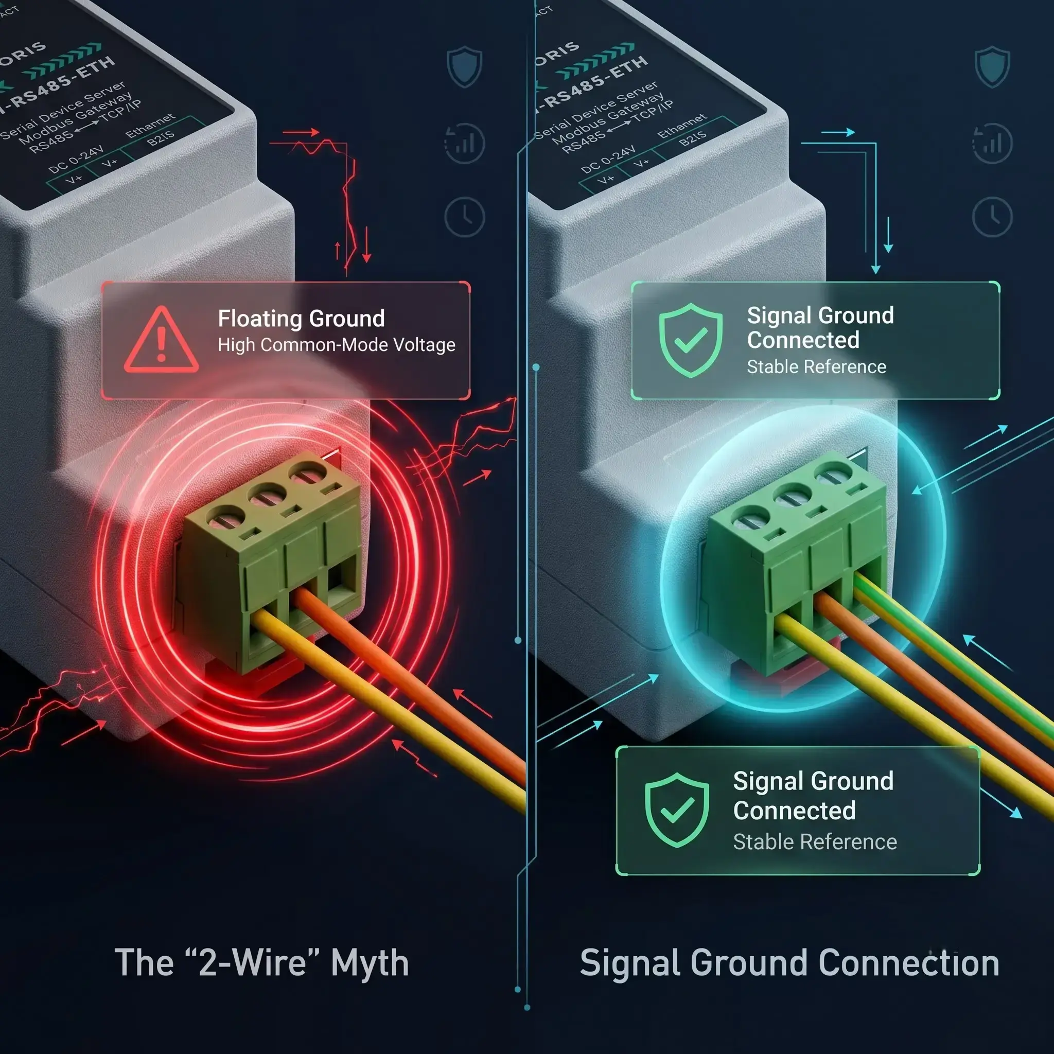
Physics is the arbiter of victory between RS485 2-wire vs 3-wire configurations. TIA-485 specifies that the receivers sense the voltage difference between A and B with respect to a common ground to determine the logic state. So the standard says ” this common mode voltage must be within a very tight range of -7V to +12V .
If you connect two devices on different building circuits without a common RS485 signal ground, the earth ground potential between them can be tens of volts different. This massive ground loop shifts the entire A/B differential signal outside the receiver’s allowable window. Relying on an RS485 floating ground is a recipe for sporadic failures or burned-out transceiver chips.
The Fix: Always run a third wire that links together all the nodes’ Signal Ground (GND/SG) terminals. Also, if a shielded cable is used, ground the shield at only one end (usually at the master side) to prevent the shield itself from being a noise-inducing ground loop.
4. A/B vs +/-: Solving RS485 Polarity Confusion and Inverted Logic
You have connected A to A, and B to B. The ground is solid. Yet, the SCADA system reads garbage data. Welcome to the industry’s most frustrating lack of standardization: Polarity Labeling.
According to the original EIA-485 specification, Terminal A is the inverting (negative) pin, and Terminal B is the non-inverting (positive) pin. However, many prominent semiconductor manufacturers (such as Texas Instruments and Maxim) decided to label A as positive (+) and B as negative (-) on their transceiver datasheets.
| Vendor/Standard | Inverting (-) Pin | Non-Inverting (+) Pin |
|---|---|---|
| Original EIA-485 Standard | A | B |
| Texas Instruments / Maxim | B | A |
| Generic Asian Hardware | D- / B | D+ / A |
Because of this RS485 polarity confusion between A and B terminals, engineers frequently wire positive to negative. When you accidentally cross the wires, you do not physically damage the chips (thanks to the differential nature). However, you cause inverted logic. A binary 1 becomes a 0, and the UART chip cannot detect the start and stop bits of the Modbus frame. The result is pure gibberish.
The Fix: Forget letters A & B. Check the + and - signs in your device manual. If the manual is not present, just swap the two data wires. If communication is made, you had them mixed up. It takes only 10 seconds and there is no risk of electrical damage.
5. Device Addressing: Unique IDs for Every Slave
When using Modbus RTU, each slave device must have its own unique address from 1 to 247. Address 0 is reserved for broadcast messages (sent to all devices at once). If you have duplicate addresses on the same bus, multiple devices will attempt to reply to the master at the exact same time, corrupting the data frame.
Address conflicts cause:
- Intermittent communication failures.
- The wrong device responding to a query.
- Constant CRC errors on the Master side.
6. The 120-Ohm Rule: Stopping RS485 Signal Reflection and Distortion
The r/embedded reddit is often filled with people asking, “My RS485 network works fine on a 10 meter bench test, but when I deploy it across a 300 meter factory floor, packets drop randomly.”
The culprit is almost always missing termination. At low speeds or short distances, engineers often skip the RS485 termination resistor (typically 120 ohms) because the system “seems to work.” However, as distance or baud rate increases, the wire behaves as a transmission line. When the high-speed electrical pulse reaches the physical end of an unterminated cable, the energy has nowhere to go. It bounces back down the wire like a wave hitting a concrete wall.
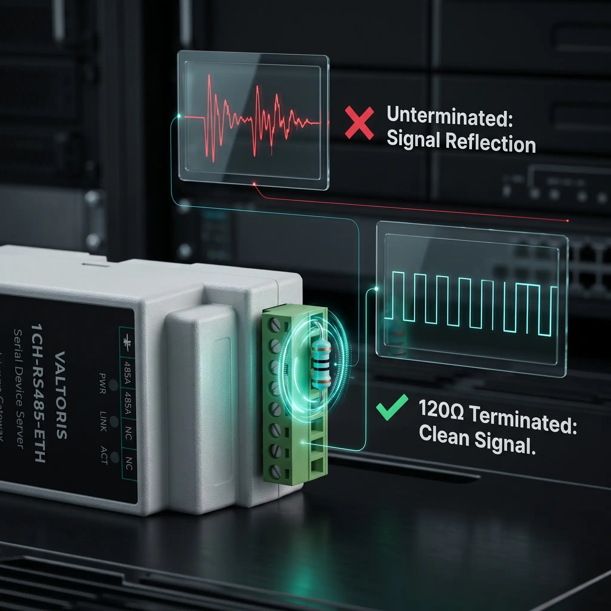
The reflected RS485 signal will disturb the new incoming data pulses. This results in a distortion of the voltage ( Ringing ) which the UART receiver interprets as erroneous bits. So, when do you need RS485 terminating resistors?
The Golden Rules of Termination:
- You must install a 120-ohm resistor strictly across the Data+ and Data- terminals of the first and last physical devices on the daisy chain.
- Never install them on intermediate nodes (in the middle of the bus), as this will overload the bus drivers and pull the voltage down too far.
- Always use termination if your cable run exceeds 300 meters or your baud rate exceeds 38.4 kbps.
7. Eliminating “Ghost” Timeouts: Network Idle Biasing vs. Termination
Perhaps the most misunderstood concept in serial networking is the difference between Termination and Biasing. If you see random timeouts occurring specifically when the network is sitting idle (no master is currently querying), you are experiencing RS485 ghost timeouts.
To prevent this, the network requires Failsafe biasing RS485. While termination stops reflections, RS485 network idle biasing sets a default logic state. This involves using RS485 pull-up pull-down resistors (typically 4.7 kΩ) to force the Data+ line high (towards 5V/3.3V) and the Data- line low (towards Ground) when no device is driving the bus.
⚡ The Field Reality (Where do you get the 5V?): Standard field sensors rarely provide external power pins to connect these resistors. Instead of hacking together an external power supply, modern architectures utilize an active gateway (like the Valtoris RS485 Server) that provides built-in, software-selectable biasing resistors powered directly by the gateway’s internal circuitry.
(Hover to reveal purpose)
Placed in parallel across D+ and D- only at the two extreme ends of the cable. Absorbs electrical wave energy to prevent ringing.
(Hover to reveal purpose)
Uses Pull-up & Pull-down resistors to force the bus into a known logic ‘1’ state during silence. Usually required only at the Master node.
8. Protocol Requirements: They Must Match
RS485 defines only the physical electrical layer; it does not dictate the data format. Therefore, all devices on a single bus must speak the exact same higher-level protocol.
Critical requirements for Modbus RTU:
- All devices must have the same baud rate (e.g., 9600).
- Same word size (usually 8 bits).
- Same parity (None, Even, or Odd).
- Same stop bits (usually 1, but sometimes 2 if Parity is None).
Both can run over RS485 but you can not mix Modbus RTU and Profibus DP on a single physical wire. They use completely different timing frames and error handling.
9. Fixing Modbus RTU CRC Errors: Why Generic Ethernet Gateways Fail
Your RS485 network is in very good shape physically. The polarity is right, the 120 Ohm resistors are in place and the biasing is active. But the instant you plug your field bus into an Ethernet SCADA system, the logs fill with Modbus RTU truncated frames and Modbus RTU CRC errors.
The failure here is no longer physical; it is architectural.
Many integrators attempt to bridge serial networks to Ethernet using cheap, generic “Transparent Serial Servers.” These devices operate blindly. They take whatever bytes arrive at the RS485 port, stuff them into a TCP packet, and fire them across the Ethernet network.
The Modbus Timing Trap: According to the official Modbus protocol specification by Modbus.org, the end of an RTU message frame is defined strictly by a silent interval of 3.5 characters. If an incoming message stops longer than this, the receiver assumes the frame is complete and begins to check the CRC.
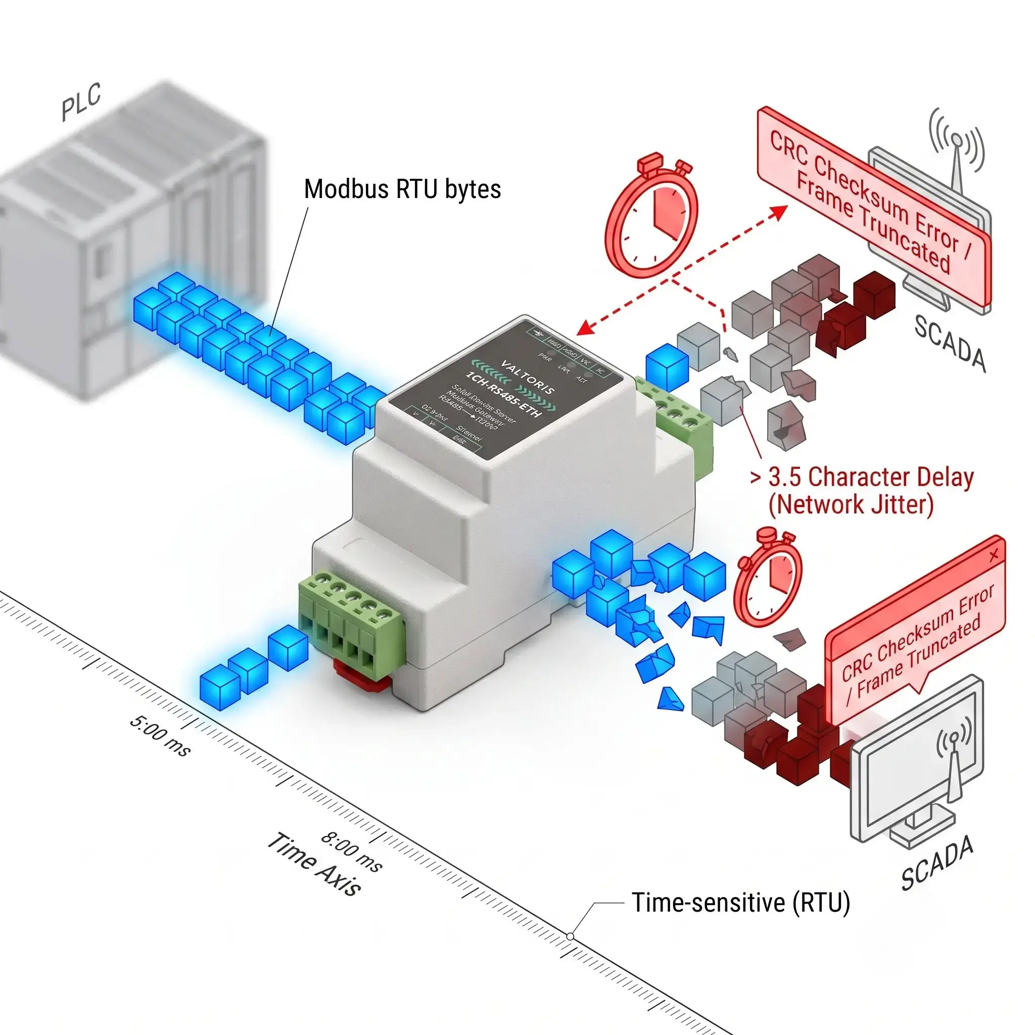
Ethernet (and especially 4G Cellular) networks are inherently non-deterministic. They suffer from latency spikes and TCP packet fragmentation (Jitter). A generic gateway might split a single Modbus RTU frame across two TCP packets. When the receiving device experiences a microscopic delay between these packets, it breaks the 3.5-character rule, prematurely cuts the frame, fails the CRC check, and throws a Serial to Ethernet gateway timeout.
The Paradigm Shift: Using a Storage Protocol Gateway
To solve protocol timeouts, you must move away from transparent passthrough and utilize an intelligent gateway with Active Protocol Translation & Caching.
Industrial edge devices, such as the standard 1CH-RS485-ETH Gateway, autonomously poll the field sensors at slow, stable baud rates and cache the data internally. When the cloud SCADA queries via Modbus TCP, the gateway responds instantly from RAM, eliminating timing jitter entirely.
Explore All Modbus Storage Gateways ➔10. Data Aggregation: Getting All That Data to One Place
Once your network is stable, you need to aggregate this data to a higher-level system. Common approaches include:
- Direct PC Connection: Using a USB-to-RS485 adapter (best for local debugging).
- Serial to Ethernet Converters: Taking the RS485 bus and making the raw data accessible over TCP/IP LAN.
- Industrial Gateways: As discussed above, these devices handle active protocol translation (e.g., Modbus RTU to MQTT or Modbus TCP) to feed modern cloud dashboards directly.
11. Isolation: Protecting Your Equipment from Electrical Surges
Even with a proper 3-wire signal ground, heavy industrial environments (like motor control centers) are plagued by massive transient voltage spikes and severe ground loops.
Deploying equipment with built-in RS485 galvanic isolation is your most robust defense. Featuring 1500V to 3000V isolation, these modules (often using optocouplers) convert electrical signals to light and back. This physically severs the electrical path, blocking destructive ground loop currents and lightning transients from traveling up the RS485 wire and frying your expensive PLC ports. (For a field-tested example, see how we use Galvanic Optical Isolation in Commercial Solar Arrays to eliminate common-mode noise and resolve CRC errors).
12. Troubleshooting Matrix: When It Doesn’t Work
Use this rapid diagnostic matrix for systematic RS485 troubleshooting to quickly isolate physical and protocol issues:
| Symptom | Likely Cause | Try This First |
|---|---|---|
| No communication at all | A/B polarity swapped | Swap A and B wires at one end. |
| Garbage data / Truncated Frames | Baud rate mismatch or Jitter | Verify baud/parity. Use a Modbus Storage Gateway for TCP. |
| Intermittent drops (High Speed) | Missing Termination | Add 120Ω resistors at both physical ends of the trunk. |
| Timeouts when network is idle | Missing Biasing | Add pull-up (to 5V) and pull-down (to GND) resistors. |
| Only some devices work | Duplicate Modbus IDs | Check DIP switches or software settings for unique 1-247 IDs. |
RS485 Field Survival Cheat Sheet & Rule Matrix
| Parameter / Topic | The Golden Engineering Rule | What Happens If You Ignore It? |
|---|---|---|
| Wiring Topology | Daisy chain (bus) only. Stubs < 3 meters. | Star/Tree topology causes signal reflections and data collisions. |
| Signal Ground | Always run a 3rd wire for Signal Ground. | Ground potential differences shift signals out of the allowable voltage window. |
| Termination (120Ω) | Only across A & B at the TWO physical ends of the trunk. | Missing termination causes standing waves and junk characters at higher speeds. |
| Idle Biasing | Use Pull-up/Pull-down to lock logic state when idle. | EMI noise triggers false start bits, resulting in ghost timeouts. |
| Galvanic Isolation | Mandatory across different buildings/power sources. | Massive voltage transients will fry transceiver chips and PLC ports. |
Frequently Asked Questions (RS485 Field Diagnostics)
How do I test if my RS485 line is working using a standard digital multimeter?
Can I use standard Cat5e or Cat6 Ethernet cable for an RS485 network?
The Catch (Impedance Mismatch): If you add the 120Ω termination resistors needed, to a 100Ω Cat5e cable, you create a minor impedance mismatch. This is acceptable for short bench tests, but the absolute best practice for harsh industrial environments or runs over 100 meters is to use dedicated 120Ω RS485 twisted pair cable (like Belden 9841)..
I have a 4-wire serial device (TX+, TX-, RX+, RX-). How do I connect it to a 2-wire bus?
What happens if I connect the RS485 shield wire to ground at both ends?
My network works perfectly on a 5-meter bench test, but drops packets when deployed on the 200-meter factory floor. Why?
Still Dealing with Unexplained Polling Timeouts?
Stop spending days guessing with oscilloscopes and termination resistors. Please tell our automation engineers about your setup below. We will analyze your physical layer and recommend the right architecture to guarantee zero data loss.
