

You have two RS485 devices, maybe a PLC in one building and a remote sensor in another, separated by a few hundred meters. The cost and complexity of new cable trenching is prohibitive, and complicated IT networks are a headache you don’t need. You just want a reliable, transparent data link.
This is exactly where a true point-to-point wireless RS485 setup excels. It acts as an invisible serial cable between your machines. However, most online guides try to force consumer-grade WiFi routers into this job, adding IP routing and network complexity that leads to polling timeouts. This guide shows you how to do it correctly using industrial serial-to-WiFi converters configured for a dedicated, direct RF link.
Let’s get into it—no fluff, no hard sell.
📡 P2P Wireless RS485 at a Glance
- Best For: Connecting two isolated serial devices (e.g., PLC to Sensor) without expensive trenching.
- Core Technology: Transparent Serial-to-WiFi bridging (No IP routing required).
- Network Dependency: ZERO. The converters form their own standalone AP/Client link.
- Typical Latency: 10–50ms (Requires adjusting Modbus timeout settings).
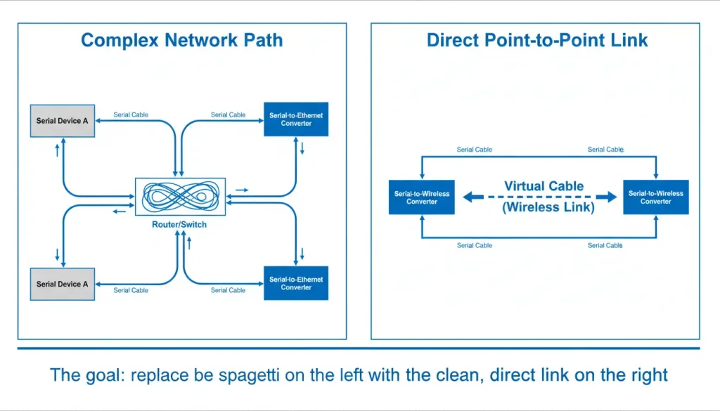
Point-to-Point in Plain English (And Why WiFi Overcomplicates It)
In an ideal world, a wireless point-to-point RS485 link should work just like a regular cable. The wireless point-to-point RS485 link is like a pipe. You put data in one end of the point-to-point RS485 link and it comes out the other end. There should not be delay and you should be able to tell how long it will take. The devices that are connected to the point-to-point RS485 link should not notice anything like addresses or special routes or changes to the data. The wireless point-, to-point RS485 link should just work like a wire.
The thing with WiFi is that it is basically a way for devices to get on a network. It is set up to work with a point that everything connects to, like a router. So when you want two devices to communicate the information has to go through a lot of steps: it has to go from one device to the point then to the router and then back to the main point and finally to the other device. This means it takes longer. There are more chances for things to go wrong like the router stopping everything from working. WiFi is like a road with a lot of traffic lights and the router is, like the traffic light that can cause a big jam if it fails.
To have a connection that goes from one point to another we need to change the way we do things. We need to make one of our wireless devices act like the network so it can make a small, private and direct connection to the other wireless device. This way the wireless device becomes the network. It creates a direct link, to the other wireless device.
📶 Wireless Topology Hierarchy (For Serial Data)
| Topology Level | Setup Method | Verdict for Industrial Use |
| Level 1 (Best) | Direct AP to Client Link: Two industrial converters paired directly. | Highly Recommended. Dedicated RF channel, lowest latency, zero IT interference. |
| Level 2 (Acceptable) | Factory Wi-Fi Router: Converters connect to the existing plant network. | Use with Caution. Requires static IPs; subject to heavy traffic congestion. |
| Level 3 (Worst) | Cloud-Routed Wi-Fi: Serial data routes to the internet and back. | Avoid for Modbus RTU. Guaranteed polling timeouts and security vulnerabilities. |
The Right Tool for the Job: What to Look For
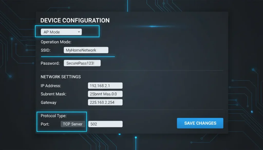
Not all wireless adapters are created equal, especially for this task. A cheap USB WiFi dongle meant for a PC won’t work. You need an industrial serial server that offers full control over its operating mode. Two critical features are non-negotiable:
- AP (Access Point) Mode: The ability for the device to generate its own WiFi network. This turns it into a mini-hub.
- Flexible Client Modes: The ability to act as a TCP Client, UDP Peer, or connect directly to a specific IP address—not just to a router’s SSID.
Devices like the Valtoris VT-WF100 tick these boxes, but any converter with similar specs will work. The key is having full control over the operating modes and IP settings.
According to a 2024 report by IMS Research, over 40% of industrial sites still rely on point-to-point serial links, and replacing cables with wireless can cut installation costs by an average of 60% [1]. The savings add up fast—no trenching, no conduit, no digging permits.
Building Your Virtual Cable: A Two-Device Configuration Guide
Let’s configure two identical converters (we’ll call them Unit A and Unit B) to create a direct link. We’ll assume a basic RS485 Modbus RTU scenario, but the principle applies to any serial protocol.
| Parameter | Unit A (The “Hub”) | Unit B (The “Client”) | Notes |
| Desired Role | Network Creator / TCP Server | Network Joiner / TCP Client | |
| WiFi Mode | AP Mode | STA (Client) Mode | |
| IP Address | 192.168.2.1 | 192.168.2.2 | Use a unique, static subnet (e.g., 192.168.2.x) |
| Subnet Mask | 255.255.255.0 | 255.255.255.0 | |
| Default Gateway | (Leave empty or 0.0.0.0) | (Leave empty or 0.0.0.0) | No gateway needed in a simple network. |
| AP SSID (from Unit A) | DIRECT_LINK_AB | DIRECT_LINK_AB | Choose a unique name. |
| AP Password | securepassword123 | securepassword123 | Use WPA2-PSK. |
| Serial Settings | Must match your PLC/Device! | Must match your PLC/Device! | Baud Rate, Parity, etc. (e.g., 9600, 8, N, 1) |
| Operating Mode | TCP Server | TCP Client | |
| TCP Server Port | 502 | — | Standard Modbus TCP port, or your choice. |
| TCP Client Target IP | — | 192.168.2.1 | Unit B is told to connect to Unit A’s IP. |
| TCP Client Target Port | — | 502 | Must match Unit A’s server port. |
💡 Field Engineer Pro Tip: Hide Your AP! When setting up the AP (Access Point) unit, never leave the SSID broadcast enabled. Hide the SSID and bind the Client unit’s MAC address directly to the AP in the web interface. This prevents factory workers’ smartphones from constantly attempting to connect to your industrial bridge, which can cause sudden latency spikes in your Modbus polling.
Step 1: Configure Unit A (The Access Point & Server)
1.Temporarily connect your computer to Unit A’s Ethernet port.
2.Access its web interface. Navigate to the Wireless or WiFi settings.
3.Set the Wireless Mode to “AP” or “Access Point”.
4.Create a Network Name (SSID), e.g., DIRECT_LINK_AB. Set a strong WPA2-PSK password.
5.Go to Network Settings. Assign a static IP address (e.g., 192.168.2.1) and subnet mask (255.255.255.0). Leave the gateway field blank.
6.Go to Serial Port or Operating Mode settings.
7.Set the Protocol or Mode to “TCP Server”. Specify a Listen Port (e.g., 502).
8.Crucially, set the serial port parameters (Baud Rate, Data Bits, Parity, Stop Bits) to exactly match your downstream RS485 device (e.g., your sensor, meter, or PLC).
9.Save the settings. The device will reboot. It is now broadcasting its own WiFi network and waiting for a TCP connection on port 502.
Step 2: Configure Unit B (The Client)
1.Move your computer and connect to Unit B.
2.In its Wireless settings, set the mode to “STA” or “Client”.
3.To get started you need to look at the list of networks. Find the name of the network you made on Unit A, which is called DIRECT_LINK_AB. Select this network from the list. Now you have to enter the password for DIRECT_LINK_AB.
4.In Network Settings, assign it a static IP (e.g., 192.168.2.2) in the same subnet as Unit A. Same subnet mask, blank gateway.
5.Go to its Serial Port / Operating Mode settings.
6.Set the Protocol/Mode to “TCP Client”.
7.In the Remote Server IP field, enter Unit A’s IP: 192.168.2.1.
8.When you are setting this up you need to put the port number that Unit A is using in the Remote Server Port field. The port number, for Unit A is 502.
9.Set the serial port parameters identically to Unit A (and your RS485 device).
10.Save the settings. The Unit B is going to restart. After that it will connect directly to the WiFi of the Unit A. Then the Unit B will try to make a connection to the Unit A using the internet address 192.168.2.1, on port 502.
Step 3: The Physical Connection & Magic
1.At each site, connect your RS485 device (Sensor A) to Unit A using a short, shielded cable (A to A, B to B). Connect your other RS485 device (Sensor B) to Unit B.
2.Provide stable power (9-24V DC) to both converters.
What you have made is really simple. Data from Sensor A goes into Unit A through the RS485 port. Then Unit A puts this data into a packet and sends it to Unit B using the private WiFi link. Unit B gets the packet takes out the data and sends it to Sensor B through its RS485 port. This all works the way around too. There is no need, for a router or the internet or a complicated network setup. Unit A and Unit B can talk to each other directly. Sensor A and Sensor B can also talk to each other through Unit A and Unit B.
Testing and Validating Your Direct Link
1.Ping Test: Connect a laptop to the DIRECT_LINK_AB WiFi network. Get an IP like 192.168.2.10. Open a command prompt and ping both 192.168.2.1 (Unit A) and 192.168.2.2 (Unit B). You should get replies. This confirms the basic wireless IP link is solid.
2.Serial Loopback Test is an useful thing to do. You need to connect the TX and RX lines of one RS485 device to a converter. You might need to use a USB-to-RS485 adapter if you are using a laptop.
Next you should use a terminal program, something like PuTTY or Tera Term. Set this program to TCP Client mode.
Then you need to connect to the IP and Port of the converter the one that is not right next, to you, the remote converter. Serial Loopback Test is a way to test things. When you type something in your terminal it should go over the wireless link come out of the RS485 port on the converter go through your jumper cable and then come back, to your terminal. This shows that the whole system is working correctly and everything is connected properly. The characters you typed in your terminal should appear again in your terminal, which means the entire chain of devices is working together without any problems and that is what makes it transparent.
When Simple Things Get a Little Complicated: Some Honest Thoughts, on Simple Matters
This method gives you an special link. The downside of having this control and simplicity is that setting it up can be a hassle. You have to create a network yourself which takes more steps than just connecting to an existing WiFi network. The Valtoris has a web interface that gives you all the options you need which’s really good but you have to be careful, with each setting. If you get the IP settings wrong or mix up the TCP Client and Server roles the link will not work. You have to pay attention to each setting when you are using the Valtoris and setting up the link. This thing is not something you can just plug in. It works. You have to set it up.. When Digital System is all set up and Digital System is running Digital System is really stable. The problem is you have to put in some work to get Digital System to that point. You have to get everything right one time and then Digital System is fine.
Beyond Two Devices: Thinking in Pairs
What if you have three sites that all need to talk to each other? Don’t build one complicated mesh. Instead, create three point‑to‑point links:
- Site A ↔ Site B (SSID: LINK_AB, subnet 192.168.2.x)
- Site A ↔ Site C (SSID: LINK_AC, subnet 192.168.3.x)
- Site B ↔ Site C (SSID: LINK_BC, subnet 192.168.4.x)
Each link is independent, simple to troubleshoot, and doesn’t create unnecessary traffic. You’re essentially building a private, deterministic network using pairs of converters—a far cry from the unpredictable nature of shared WiFi.
Quick Recap
- Understand that regular WiFi adds complexity—you want a direct link, not a network.
- Choose industrial converters with AP mode, TCP Server/Client, and rugged hardware.
- Configure Unit A as AP + TCP Server, static IP.
- Configure Unit B as STA + TCP Client, static IP in same subnet, pointing to Unit A.
- Match serial settings exactly on both ends.
- Test with ping and serial loopback.
- For multiple sites, think in pairs—each link gets its own SSID and subnet.
Most problems come down to mismatched serial settings or swapped client/server roles. Get those right, and you’ll have a transparent, reliable wireless cable.
Ready to Deploy Your Wireless RS485 Link?
Every industrial site has unique RF challenges. If you want to bypass the trial-and-error phase, you need hardware built specifically for transparent serial bridging.
- [Explore Our Industrial Serial-to-WiFi Converters]
- [Contact Our Engineering Team] for a free topology review and project quote.👇
🛡️ Why Valtoris Created This Guide
Valtoris has spent over a decade engineering industrial networking hardware for harsh environments. This guide synthesizes field data from our deployment of thousands of serial-to-wireless converters across water treatment facilities, automated warehouses, and smart grid infrastructures. We write this because we see too many integrators failing with consumer-grade routers, and we want to provide a definitive, zero-BS guide to doing wireless RS485 right.
Frequently Ask Questions
Q1: Will bridging Modbus RTU over a Wi-Fi link cause polling timeout errors in my PLC?
A: It can, if you don’t adjust your master settings. While the converters are transparent, converting serial data to TCP/IP packets and transmitting them over RF introduces slight latency (typically 10–50ms) compared to a hardwired copper cable. You will likely need to increase the “Response Timeout” threshold in your Master PLC or SCADA software to prevent false communication drops.
Q2: What is the realistic distance of a 2.4GHz link, and do I need clear Line of Sight (LOS)?
A: In the open area with clear LOS you can expect about 100 to 300 meters range with typical 3dBi omnidirectional antennas. But 2.4GHz signals don’t travel well through concrete and metal. If your converters are housed inside steel control panels, you must use external magnetic antennas routed to the outside. For distances exceeding 1 kilometer or penetrating heavy industrial obstacles, you should abandon Wi-Fi and use our [Industrial LoRa Wireless Modules].
Q4: Since RS485 data is unencrypted, is my wireless point-to-point link vulnerable to hacking?
A: The Modbus RTU payload itself is not encrypted, so securing the RF layer is key. Don’t leave it open when you set the converter into AP (Access Point) mode. Encryption should always be WPA2-PSK, SSID broadcast should be hidden, and use MAC address filtering. This ensures only your designated Client converter can associate with the AP, creating a secure, invisible wireless tunnel. For projects requiring hardware-level AES encryption and mesh routing, consider our [Industrial Zigbee Gateways].