

You deployed a wireless bridge to replace that final, impossible mile of RS485 cable to your solar string inverters. The theory was simple. But now, the connection drops randomly, Modbus data is garbled, or the bridge mysteriously reboots every day at dawn.
Solar sites are brutal environments. Wide temperature swings, electromagnetic interference (EMI) from humming inverters, and ground loop voltages will expose the flaws in generic wireless hardware almost immediately.
This guide skips the basic “how to plug it in” tutorials. Instead, we are looking at real-world diagnostics. Here is how field engineers troubleshoot and permanently fix RS485 wireless bridge failures.
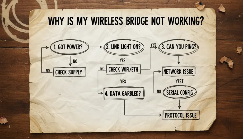
Quick Diagnosis: Find Your Problem in 30 Seconds
| What you’re seeing | Most likely culprit | Jump to |
|---|---|---|
| Bridge reboots randomly (especially at dawn/dusk) | Power supply instability | Power Problem |
| Data is corrupted, random characters, or no response | Ground loops or EMI | The Silent Killer |
| You can ping the bridge, but monitoring software sees nothing | Modbus TCP / RTU mismatch or serial settings wrong | The Configuration Trap |
| WiFi signal “good” but connection is slow or drops | Signal quality vs. strength, interference | The Wireless Mirage |
| Data arrives but values are clearly wrong (65535, 0, nonsense) | Modbus register mapping or byte order | The Protocol Mismatch |
If you’re still not sure, just start at the top—the most common failure point is power, and it’s often overlooked.
1. The Power Problem: It Is Not Just About Voltage
You connected a 12V supply, to the circuit and the light emitting diode lit up. That is good right? Maybe that is not the case.
What you’ll see:
The bridge keeps restarting. This often happens at dawn or dusk, exactly when the inverter’s cooling fan turns on. Data logs show gaps at those times.
Why it happens:
The power line has voltage drops or extra electrical noise. Long thin wires and the inverter itself can cause this. Many cheap wall adapters don’t regulate output well under load, and when the fan kicks in, the voltage sags just enough to reboot the bridge.
How to fix it
- Use a Regulated, Industrial Power Supply: Don’t repurpose a random adapter. Use a dedicated, switch-mode power supply (SMPS) designed for 9-24V DC with a stable output.
- Localize Power: Keep the power supply close to the bridge. If running wire, use a gauge thick enough to prevent voltage drop over distance.
- Consider Isolation: In electrically noisy environments, a small, isolated DC-DC converter between your main supply and the bridge can clean the power perfectly.
A note on device selection:
When we talk about a device like the Valtoris VT‑WF100, its wide input range (9–24V DC) isn’t a gimmick. It means the internal power circuitry is designed to handle the kind of dirty, fluctuating power you actually get on a solar site. That’s one less thing to debug later.
2. The Silent Killer: Ground Loops & EMI
Your wiring is correct, but the data is a mess of corrupted characters or the communication is “noisy.”
The Failure: Random communication errors, checksum failures in your Modbus data, or complete lock-ups that clear after a power cycle.
The Root Cause:
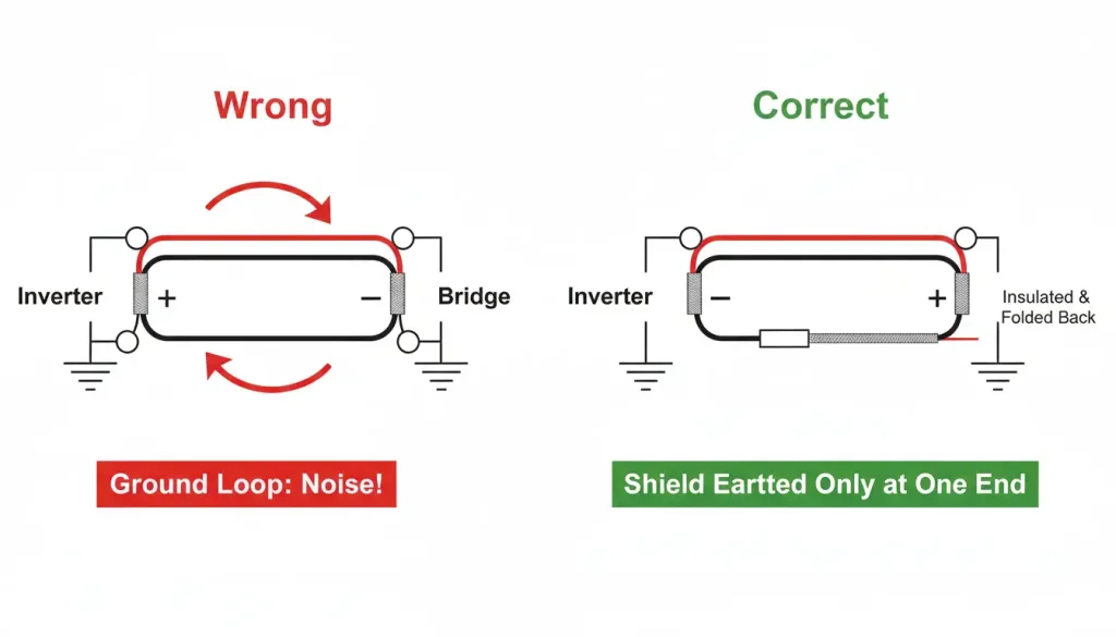
1. Ground Loops: If your string inverter and your data acquisition cabinet are grounded at different points (especially over long distances), a potential difference can exist. This voltage drives current through the shield of your RS485 cable, inducing noise directly onto the data lines.
2.Electromagnetic Interference (EMI): The inverter itself is a powerful source of high-frequency noise. A wireless bridge with a plastic case and poor internal layout sits right in this field, which can scramble its internal logic or radio.
How to fix it
- When you are using a RS485 cable you should only connect the shield at one end. This is usually, at the ground terminal of the bridge. Do not connect the shield at the end, which is the inverter end. You can just leave it alone. Make sure it is insulated. This will stop the ground loop from happening with your RS485 cable.
- Use Proper Cable: Always use a shielded, twisted-pair cable for the RS485 run, even if it’s only 1 meter long. The twist cancels noise, the shield contains it.
- Demand Metal & Protection: The bridge’s metal enclosure acts as a Faraday cage, blocking external EMI. Built-in surge protection on the RS485 port isn’t just for lightning; it clamps high-voltage noise spikes from the inverter. This isn’t a luxury for solar applications; it’s mandatory.
According to IEEE Std 1580‑2010, proper grounding and shielding practices for RS485 in industrial environments significantly reduce bit error rates caused by electromagnetic interference. Ignoring them turns a reliable communication link into an intermittent headache.
3. The Configuration Trap: It’s Not Just an IP Address
You can send a signal to the device. It will respond, but the program you use to keep an eye on things does not show anything about the device. The device is basically invisible, to your monitoring software even though you can ping the device.
The Failure: The network link is up, but no data flows to your SCADA or data logger.
The Root Cause: A mismatch in the communication stack. You’ve configured the network layer (IP), but the data layer (protocol) is wrong. The bridge is just passing along bits, not translating them correctly between the inverter’s world (Modbus RTU over serial) and your network’s world (Modbus TCP).
How to fix it
- Set the bridge to Modbus TCP Server (or Gateway) mode. This lets it listen on port 502, translate Modbus TCP requests to Modbus RTU, and send them to the inverter.
- Mirror the serial settings. The bridge’s baud rate, data bits, parity, and stop bits must match your inverter’s communication settings exactly. Check the inverter manual—common values are 9600, 8, None, 1, but don’t guess.
- Static IP is king. Always assign a static IP to the bridge. DHCP leases expire and can change, breaking your monitoring system’s connection.
Configuration Checklist Template
Use this table to plan and record all critical settings for your wireless bridge before and during setup. This ensures no parameter is overlooked.
| Parameter | Value / Check | Notes & Example |
| Network Settings | ||
| Device IP Address | ________________ | Static IP recommended. e.g., 192.168.1.150 |
| Subnet Mask | ________________ | e.g., 255.255.255.0 |
| Default Gateway | ________________ | Your router’s IP, e.g., 192.168.1.1 |
| WiFi Settings (STA Mode) | ||
| WiFi SSID | ________________ | Your site’s wireless network name. |
| WiFi Password | ________________ | Use WPA2-PSK security. |
| Serial Port Settings | MUST match your inverter’s manual exactly. | |
| Baud Rate | ________________ | Common: 9600, 19200, 38400, 115200 |
| Data Bits | ________________ | Almost always 8 |
| Parity | ________________ | None, Even, or Odd |
| Stop Bits | ________________ | Almost always 1 |
| Protocol & Operating Mode | ||
| Operating Mode | ________________ | Set to Modbus TCP Server or Modbus Gateway |
| TCP Port | ________________ | Default is 502 |
| Device Identity | ||
| Slave ID / Unit ID | ________________ | The Modbus address of your inverter (e.g., 1) |
| Physical Connection Notes | ||
| RS485 A(+) Terminal | Connected to Inverter A(+) | ✅ Verified |
| RS485 B(-) Terminal | Connected to Inverter B(-) | ✅ Verified |
| Shield Grounding | Connected at Bridge end ONLY | ✅ Verified |
🖨️ Don’t Configure in the Dark. Take This to the Field.
Stop scrolling on your phone under the glare of the sun. Download this configuration checklist as a printable PDF for your field technicians to ensure zero missed parameters during installation.
4. The Wireless Mirage: Signal Strength vs. Signal Quality
Your bridge shows “connected” to the WiFi, but the connection is slow or drops packets.
The Failure: Intermittent timeouts, high latency in data, or the bridge disassociating from the network.
The Root Cause: WiFi is designed for offices, not steel cabinets next to metal-housed inverters. A “good” signal strength (RSSI) doesn’t guarantee a good Signal-to-Noise Ratio (SNR). The 2.4GHz band is also crowded with other devices.
How to fix it
- Site Survey, Even a Simple One: Use a WiFi analyzer app on your phone near the inverter location. Check for channel congestion.
- Antenna Matters: If the bridge has an external antenna (RP-SMA connector), replace the stock stubby antenna with a small, properly tuned dipole or omni antenna mounted outside the metal cabinet if possible.
- The Wired Backup: This is the single most underrated feature. Choose a bridge that offers simultaneous WiFi and Ethernet connectivity. Use WiFi as the primary, but run a single Ethernet cable as a permanent backup or for initial stable configuration. This redundancy is a lifesaver during troubleshooting. It’s a feature that turns a potential support nightmare into a manageable hiccup.
5. The Protocol Mismatch: When the Data Arrives but Makes No Sense
Data is coming through, but the values are clearly wrong (e.g., power reading is 65535 or 0).
- The Failure is when you have application layer errors. This means that your software is actually connected. It is reading complete nonsense from the other end. The software thinks it is getting information. It is really just getting a bunch of nonsense that does not make any sense. This is what The Failure is it is like your software is connected. It is not getting anything useful just nonsense.
- The problem is that your monitoring software is looking at the Modbus register or it is reading the bytes in the wrong order. This is not a problem with the bridge. The bridge is doing its job. Sending the data correctly. The issue is with the monitoring software. The monitoring software is the one that is having trouble getting the data, from the Modbus register. The Modbus register is being read incorrectly by the monitoring software.
How to fix it
- Get the inverter’s Modbus map. This is the manufacturer’s document that tells you which holding register (4xxxx) contains which value—DC voltage, AC power, etc. Without this, you’re guessing.
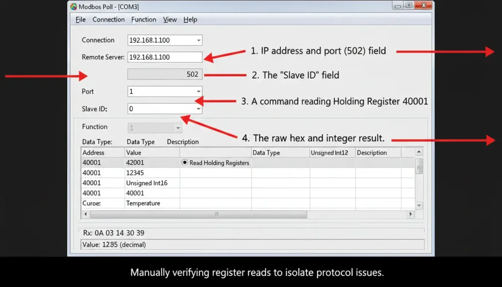
- Use a debug tool. Tools like Modbus Poll let you manually read holding registers using the bridge’s IP address. If you get sane numbers there, the problem is in your monitoring software’s configuration.
- Check byte/word order. Some devices use “byte swap” or “word swap.” If a register reads scrambled (e.g., 0x1234 appears as 0x3412), adjust the swap setting in your software.
The Modbus.org application note “Modbus over Serial vs. Modbus TCP” emphasizes that gateway devices must correctly map register data without altering byte order unless explicitly configured. Always verify your gateway’s settings against the inverter’s requirements.
Choosing the Right Device for the Job
A reliable setup doesn’t come from luck. It comes from choosing hardware designed for the environment.
| Feature | Consumer‑grade bridge | Industrial‑grade bridge (e.g., Valtoris VT‑WF100) |
|---|---|---|
| Enclosure | Plastic | Metal (Faraday cage) |
| Input voltage | Fixed 5V or 12V | Wide range 9–24V DC |
| RS485 protection | None | Surge protection, isolated |
| Operating temp | 0–40°C | –30°C to 75°C |
| Antenna | Internal or fixed | External RP‑SMA (upgradable) |
| Backup connectivity | No | Simultaneous WiFi + Ethernet |
If your site experiences temperature swings, electrical noise, or unreliable power (and most solar sites do), industrial features aren’t “nice to have”—they’re what keeps the system running.
Your Next Steps
You’ve made it through the most common failure points. Now, instead of guessing, you have a clear path:
- Start with the Quick Diagnosis table. Pick the symptom that matches.
- Verify power first. It’s the easiest to overlook and the most frequent culprit.
- Check grounding and shielding. A single‑ended shield connection solves many “mystery” errors.
- Confirm serial and Modbus settings. Use the checklist to avoid mismatches.
- If wireless is unstable, consider a wired backup. Redundancy pays off.
The Permanent Fix: Stop Using Consumer Hardware
Troubleshooting ground loops and EMI is frustrating, but the root cause of 90% of solar site failures is simple: using consumer-grade Wi-Fi bridges in an industrial environment. If your hardware lacks isolated RS485 ports and a wide-voltage input, you will be constantly rolling trucks to reboot frozen devices.
Stop guessing and start upgrading.
The [Valtoris VT-WF100 Industrial RS485 to Wi-Fi Bridge] is built for rugged solar and SCADA applications. It has built in surge protection, a rugged metal enclosure and a 9-24V DC wide voltage input that shrugs off dawn/dusk power fluctuations.
Frequently Asked Questions
Q1: Do I still need a 120-ohm termination resistor if the RS485 cable connecting the inverter to the wireless bridge is very short?
Q2: Can I connect multiple string inverters to a single RS485 Wi-Fi bridge?
Q3: My SCADA system is timing out when polling data, but the bridge’s Wi-Fi signal is at 100%. What is wrong?
Solar Site Topology Rescue
Still dropping packets after replacing power supplies and fixing ground loops? Don’t let a generic Wi-Fi bridge compromise your entire string inverter array. Tell us your exact hardware setup below, and our networking engineers will spec a ruggedized bridge guaranteed to handle the EMI load.
.