
Centralized PLC I/O architectures are a chronic maintenance liability. Routing 500 meters of multi-core copper cable to connect remote limit switches and solenoid valves creates a fragile infrastructure where a single wire break can halt production for hours. The industry has shifted: industrial Ethernet now accounts for over 70% of new factory network nodes. Deploying edge-based Ethernet I/O modules directly at the machine level effectively replaces hundreds of vulnerable analog points with a single RJ45 uplink.
Traditional Centralized I/O
PLC
Decentralized Ethernet I/O
Module
PLC
However, standard Ethernet I/O introduces new vulnerabilities. Evaluating decentralized I/O in 2026 requires looking past basic connectivity and addressing severe operational risks: network failure resilience, Modbus TCP polling latency, IT/OT data integration, and legacy RS485 bottlenecks. The boundary separating a passive “dumb” Remote I/O node from a “smart” Distributed I/O controller has permanently blurred.
This guide analyzes six engineering metrics to evaluate before specifying an Ethernet I/O architecture: network failure resilience, polling latency, peer-to-peer capabilities, IT/OT protocol integration, legacy device handling, and physical cabinet density.
📊 The “PLC-Bypass” ROI Calculator
Calculate your immediate infrastructure savings by utilizing Peer-to-Peer Ethernet I/O (Pair-Connection) to mirror signals across a facility, completely eliminating the need to specify, program, and wire an intermediary micro-PLC.
1. The Disconnect Dilemma: What Happens When the Network Fails?
This is the ultimate nightmare scenario for any experienced controls engineer. The moment you physically remove your discrete I/O from the local PLC backplane and push it out onto a Local Area Network (LAN), the inevitable result is a critical single point of failure: the Ethernet switch infrastructure and the cabling itself.
If a rogue forklift snips the Cat6 trunk line that runs between a standard, passive Remote I/O module and the central PLC, the remote module goes blind. Most importantly, a “dumb” module will just remember its last state forever. If a heavy-duty water pump was ordered to run only milliseconds before the cable was cut, that pump would continue to run until a human physically intervened, possibly leading to a catastrophic spill. The host PLC will detect the dropped TCP socket and will set an internal fault flag but is physically unable to prevent the remote actuator.
Advanced Ethernet I/O controllers circumvent this fatal flaw through the implementation of localized Edge Logic. Instead of operating as mindless slaves to the PLC’s polling cycle, these modules execute autonomous safety protocols at the hardware level.
Next-generation industrial modules incorporate a specialized firmware mechanism known as the DO Hold Time. Integrators can program the module to have a strict millisecond timeout window. If the module does not receive a valid Modbus TCP heartbeat or write command from the host PLC within this time frame (e.g. 3 seconds), the module’s microprocessor forces a hardware interrupt. It immediately takes over the last known state and de-energizes the Digital Output (DO) relays automatically. If the network is fully isolated the valve closes , the pump switches off and the system goes to a safe state .
Beyond timeout protections, these edge-enabled modules natively support DI Controls DO functionality. This enables engineers to wire a physical Emergency Stop or high-limit level switch directly into the module’s Digital Input (DI1) and internally map it to the module’s Digital Output (DO1). When the limit switch is tripped, the module immediately cuts power to the local relay. This action takes place entirely within the internal circuitry of the module – without the signal having to travel over the network to the PLC and back. Then network latencies and switch failures are totally irrelevant for your most critical local safety interlocks.
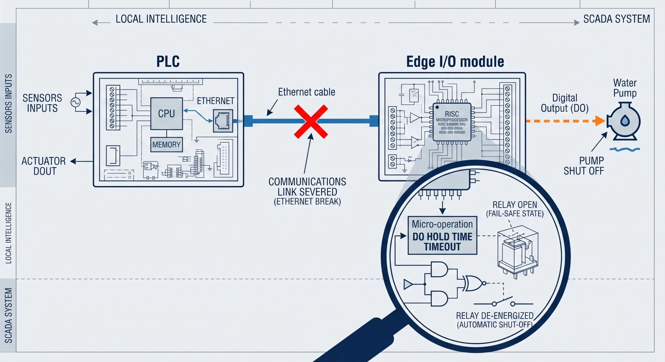
| Failure Scenario | Standard “Dumb” Remote I/O | Advanced Edge-Logic I/O |
|---|---|---|
| Ethernet Trunk Line Severed | Outputs freeze in the last commanded state indefinitely. High risk of mechanical over-travel or fluid spills. | DO Hold Time triggers; relays automatically revert to a predefined safe state (open) upon heartbeat timeout. |
| Local Safety Switch Triggered (LAN Down) | Signal is trapped at the edge; cannot reach the PLC to initiate shutdown. Actuator remains energized. | DI Controls DO instantly cuts local relay power internally, completely bypassing the paralyzed network. |
| Power Cycle / Hard Reboot | Outputs may flutter or behave unpredictably until the PLC boots up, reconnects, and asserts control. | DO PowerOn Config ensures hardware relays power up in a strict, pre-determined safe state (e.g., `0x00` all open) before the TCP socket even initiates. |
2. Modbus TCP Polling Latency: Will Ethernet I/O Kill My Scan Time?
Modbus TCP is the de-facto universal language of the industrial automation created by the Modbus Organization. Open, robust, and supported across all SCADA and HMI platforms. However, it is still fundamentally built on a polling methodology of Master/Slave (Client/Server).
In a large scale deployment with 50 traditional Remote I/O nodes, the central PLC has to ask each module “What is your DI status? “What are your AI values?” and then wait for the TCP acknowledgment. Even on Gigabit Ethernet, the total socket turn-around time for 50 sequential nodes can easily drive your PLC’s network scan cycle to 250mS or more. A 250ms blind spot is an unacceptable operational liability for high-speed sorting conveyors, synchronized motion control, or rapid fault detection.
The technological leap required here is transitioning from passive, continuous polling to Active Reporting (Change-of-State).
Modern Ethernet I/O controllers fundamentally alter network bandwidth consumption by acting proactively. Instead of forcing the PLC to constantly poll for data that hasn’t changed, the I/O module’s internal processor monitors its own terminals. The exact millisecond a Digital Input state changes (e.g., a photo-eye detects a passing component), the module instantly packages that specific change into a Modbus TCP packet and pushes it asynchronously to the server.
This logic applies to Analog Inputs (AI) as well. Engineers can configure a precise Auto-Report Time parameter. By setting `Ai1 Auto-report: 1000ms`, the module will autonomously sample the 4-20mA loop and push the holding register values to the SCADA system exactly once per second. This paradigm shift entirely frees up the central PLC’s CPU cycles for complex control algorithms rather than mundane data gathering, effectively dropping network-induced latency to near zero.
| Performance Metric (50 I/O Nodes) | Traditional Modbus TCP Polling (100ms cycle) | Active Reporting (Change-of-State) |
|---|---|---|
| Network Traffic Volume | 500 Requests + 500 Responses per second (Constant broadcast flooding). | Near-zero idle traffic; transmits only when a physical terminal state changes. |
| PLC CPU Utilization | High (Wasting cycles processing thousands of unchanged register values). | Low (Only interrupts the CPU when actionable hardware data arrives). |
| Event Detection Latency | Up to 100ms+ (Highly dependent on where the event falls within the sequential poll loop). | <10ms (Instantaneous push to the TCP socket upon hardware trigger detection). |
3. Bypassing the PLC: Can Ethernet I/O Modules Talk Peer-to-Peer?
Suppose you have an application where a high level float switch in a storage tank must turn on a transfer pump 800 meters away in another plant. In a conventional topology, you wire the sensor to an input module, send that data over the network to a central PLC, write specific ladder logic to evaluate the input, then send a command back over the network to an output module to energize the pump.
That’s a massive over-complication for a simple signal mirror. It adds extraneous software programming work , adds network latency , and depends on an expensive centralized point of failure .
This is where Peer-to-Peer (Pair-Connection) capabilities disrupt the industrial layout. Advanced Ethernet I/O modules can communicate with each other over the existing LAN or Fiber optic backbone of the facility via the firmware resulting in an infinite distance ‘virtual wire’.
This architecture completely eradicates the PLC from simple control loops. By leveraging hardware-level serial decoding and bypassing the PLC’s software scan cycle entirely, the relay transmission speed—the time from the sensor triggering to the remote relay closing—is reliably reduced to <30 milliseconds.
| Requirement | Legacy PLC-Routed Architecture | Peer-to-Peer I/O (Pair Connection) |
|---|---|---|
| Hardware Dependency | Remote Input Node + Main PLC Chassis + Remote Output Node. | Input Node + Output Node (Zero PLC involvement). |
| Software Engineering | High (Requires writing, compiling, and debugging ladder logic or structured text). | Zero-Code (Simple IP address and port mapping via a GUI configuration tool). |
| System Latency Path | Sensor → LAN → PLC Scan Cycle → LAN → Actuator. | Sensor → LAN → Actuator (<30ms end-to-end typical). |
4. The IT/OT Divide: Can Your I/O Module Speak MQTT & JSON?
The industrial landscape is undergoing a massive convergence. Operational Technology (OT) engineers require the deterministic reliability of Modbus RTU/TCP for machine control, but Information Technology (IT) departments demand data visibility. Corporate cloud dashboards, data lakes, and platforms like AWS IoT Core or AliCloud do not natively parse Modbus holding registers or hexadecimal payloads. They require modern, lightweight web protocols: specifically, MQTT and JSON.
Historically, bridging this divide was a costly endeavor. To push a 4-20mA flow meter reading to a cloud database, an integrator had to wire the sensor to a standard I/O block, poll it with a PLC, and then install a dedicated Industrial Edge Gateway (IPC). This IPC would run custom middleware—often Node-RED or Python scripts—to translate the Modbus arrays into formatted JSON strings and publish them via an MQTT broker. This multi-tier approach easily adds $1,000+ per node in hardware and custom coding.
The standard for 2026 demands that the I/O module itself must function as the IoT Gateway.
A major fear among automation engineers is that deploying “Edge IoT” requires retraining their teams in C++ or Python. This is no longer the case. Advanced edge controllers, such as the 8CH-IO-LTE and 8CH-IO-ETH, have completely eliminated the coding barrier. They feature native, embedded MQTT client stacks managed entirely through a Zero-Code graphical interface.
Using a standard Windows-based configuration utility, an engineer simply inputs the MQTT broker’s IP address, specifies the standard port (e.g., 1883), and defines the Publish and Subscribe Topics. But the true engineering advantage lies in the “JSON To Modbus RTU Settings” interface.
Instead of writing C++ arrays, the engineer clicks “Add JSON Node”. From drop-down menus, they assign Modbus Function Code 04 (Read Input Registers) to target a specific sensor, set the data length to 2 bytes, and define the data order (Big Endian). Finally, they set a Data transmit interval (e.g., 1000ms). The module’s internal processor autonomously handles the polling, translates the hex data, and packages it into a human-readable JSON payload—such as {"Temperature_AI1": 45.2}. It then publishes this telemetry to the cloud. No middleware, no Python scripts, no external IPCs required.

| Architecture Component | Traditional Multi-Tier Integration | Integrated Edge MQTT I/O |
|---|---|---|
| Data Acquisition Hardware | Standard Modbus I/O Block ($200 – $350) | All-in-One Controller (e.g., 8CH-IO-ETH) Simultaneously handles physical I/O sampling, protocol translation, and secure cloud publishing internally. |
| Protocol Translation Hardware | Industrial Edge IPC / Gateway ($800 – $1,500) | |
| Software Engineering | High (Custom Python, Node-RED, ongoing OS patching). |
5. The Hidden Cost of Legacy Gear: Why You Need Built-In Serial Gateways
Facility upgrades are rarely done on a blank canvas. You are opening up an existing control cabinet to install a new Ethernet I/O module and there it is, legacy RS485 equipment hanging on the DIN rail. An older Variable Frequency Drive (VFD), a smart digital power meter or PID temperature controller that only speaks 2-wire Modbus RTU.
The standard practice to get these legacy field devices onto your new Ethernet backbone is to buy and install a standalone Serial-to-Ethernet Device Server. This consumes precious DIN-rail real estate, adds another 24V power drop, and yet another IP address to your network management spreadsheet.
True industrial-grade Ethernet I/O modules solve this hardware bloat by including independent, built-in Serial Server functionality.
One can look at the architecture of the 8CH series controllers and see a key design decision: dual RS485 interfaces. The main port (`485-IO`) is only used for local expansion and for querying the module’s own physical I/O states. However, the secondary port (either `485-Network` or `485-4G`) is a fully independent transparent serial gateway.
This secondary port enables system integrators to directly daisy-chain in their legacy RS485 power meters. The I/O module will transparently encapsulate the meter’s Modbus RTU traffic and forward it over its primary Ethernet or LTE uplink to the SCADA system while processing its own DI/DO/AI control tasks at the same time. You get an 8-channel I/O controller and an industrial serial device server in one footprint.
| Integration Factor | Separate Modules (I/O + Serial Server) | Integrated Dual-Bus I/O Controller |
|---|---|---|
| DIN-Rail Space Consumption | High (Requires physical mounting space for two distinct devices). | Minimal (Consolidated into a single compact housing). |
| Network IP Allocation | Requires 2 distinct IP addresses/MAC addresses. | Requires only 1 IP address for both I/O and Serial pass-through. |
| Power Supply Infrastructure | Requires dual 24V DC terminal drops. | Single power drop supplies both functions. |
6. Cabinet Real Estate & Electrical Safety: Maximizing DIN-Rail Density
Finally, we must confront the physical realities of installation and electrical safety. A pervasive misconception pushed by aggressive marketing is that all modern remote I/O must be heavy-duty, IP67-rated, machine-mount blocks. While IP67 is necessary for bolting directly onto a wash-down CNC machine, it is an exorbitant and inflexible overkill for 80% of standard industrial applications.
The vast majority of remote I/O actually resides inside secondary junction boxes, Motor Control Centers (MCCs), or indoor facility cabinets. In these IP20 environments, engineers prioritize DIN-Rail density, power resilience, and robust electrical isolation above waterproofing.
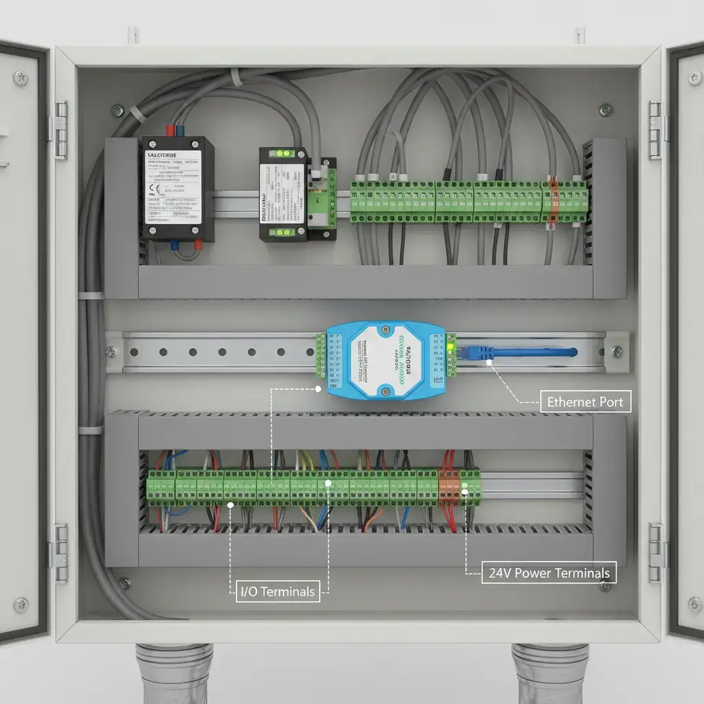
Deploying reliable I/O requires hardware designed to survive the electrical chaos of a factory floor. When specifying modules, engineers must verify three critical physical parameters:
- Wide Voltage Inputs (9~24V DC): Industrial power grids are notoriously noisy. When large inductive loads (like heavy compressors) start up, line voltage can sag significantly. A module designed with a wide 9-24V DC input tolerance ensures the internal processor does not reboot during brownouts.
- Optocoupler Isolation for Wet/Dry Nodes: Wiring sensors across different areas of a plant often introduces varying ground potentials. High-quality modules utilize optocoupler isolation on all Digital Inputs. They seamlessly handle passive dry contacts (simply shorting the pin to GND) and active wet nodes with strict voltage thresholds (e.g., recognizing 0~17V as Low and 17~24V as High on a 24V system) to physically sever ground loops.
- 2KV ESD Ethernet Protection: The RJ45 Ethernet port is the Achilles’ heel for static discharge. Industrial modules must feature internal 2KV ESD (Electrostatic Discharge) and surge protection on the network interface. This prevents localized electrical faults—like a motor chassis leaking current—from traveling up the Cat6 cable and frying expensive upstream managed switches.
Expert FAQ: Troubleshooting Advanced Ethernet I/O Integration
Based on the most pressing technical discussions from senior OT engineering communities, here are definitive answers to deploying edge-enabled Ethernet I/O architectures.
Yes, dual bus architecture is used. Advanced edge modules have physically separated interfaces (e.g. Ethernet/LTE uplink and local 485-IO port). The local PLC can continuously read the sensors via Modbus RTU on the local RS485 bus and the module packages that same I/O data into JSON and pushes it to a MQTT broker on the Ethernet/LTE uplink.
They are managed at various levels. If the Ethernet socket is disconnected, the internal DO Hold Time logic of the module is activated and the outputs are changed to a safe state after a TCP timeout. The module detects a physical break in the sensor wire: for example a 4-20mA Analog Input (AI) will fall to 0mA and this is detected by the module. A PLC or Cloud dashboard can be programd to trigger a wire-break alarm whenever the AI value is below the 4mA threshold.
Naw. Standard Peer-to-Peer I/O uses dedicated, unicast TCP sockets, instead of flooding a network and requiring IGMP snooping (as multicast protocols such as EtherNet/IP implicit messaging do). Module A ( Client ) is told the exact IP address of Module B ( Server ) . This ensures that it functions perfectly on normal, unmanaged industrial switches without generating broadcast storms.
The DO PowerOn Config feature allows engineers to prevent dangerous automatic restarts. On power-up or network re-connect you are able to configure the starting state of all relays (eg, hex `0x00` for all open). Once the TCP socket is recovered, the host PLC has to explicitly send a new Modbus 05 (Force Single Coil) command to energize again the relays.
It depends on the module hardware. Standard modules will lose telemetry durinstorage. When the network is restored, it bulk uploads the historical data so you have no gaps in telemetry in your cloud database.g an outage. Premium edge controllers however have an Enable Off-line Storage mechanism. Should the TCP socket to the MQTT broker go down, the module writes the JSON payloads to internal flash
Ready to Upgrade Your Network Architecture?
As you think about your next facility expansion, consider the exorbitant costs of central PLC programming, fragile copper wiring and unplanned downtime versus the capabilities of decentralized, edge-enabled I/O.
Learn how state-of-the-art Ethernet and LTE I/O controllers marry Zero-Code MQTT, Peer-to-Peer automation, and hardware-level safety interlocks for the future-proofing of your industrial network.
Explore Industrial I/O Controllers