
Serial to Ethernet Converters
Industrial-Grade Serial Device Servers & Modbus Gateways
Don’t let Modbus timeouts and RS485 polling collisions slow down your OT integration. 1500V-3000V optical isolation, Virtual COM drivers and automatic TCP conversion from -40°C to 85°C extremes are all part of our serial device servers.
Hardware Specification Matrix
Verified technical parameters sorted by port density. Select your precise serial configuration below.
| Model / Series | Serial Interface | Ethernet Ports | Electrical Protection | Power & Mounting | Action |
|---|---|---|---|---|---|
| 1CH-RS485-ETH | 1 × RS485 Only | 1 × RJ45 | 2KV Surge Protection | 9~24V DC | 35mm DIN | Specs |
| 1CH-RS232/485/422-ETH (V) | 1 × 3-in-1 | 1 × RJ45 | 2KV Surge Protection | 9~24V DC | Desktop | Specs |
| 2CH-RS485-ETH | 2 × RS485 Only | 1 × RJ45 | 2KV Surge Protection | 9~24V DC | DIN-Rail | Specs |
| 2CH-RS485-ETH (VI) | 2 × RS485 Only | 1 × RJ45 | 1500V Isolation | 9~24V DC | DIN-Rail | Specs |
| 2CH-RS232/485/422-ETH | 2 × 3-in-1 | 2 × RJ45 (Cascade) | 2KV Surge Protection | 9~24V DC | DIN-Rail | Specs |
| 4CH-RS485-ETH | 4 × RS485 Only | 1 × RJ45 | 2KV Surge Protection | 9~24V DC | DIN-Rail | Specs |
| 4CH-RS485-ETH (VI) | 4 × RS485 Only | 2 × RJ45 (Cascade) | 3000V Isolation | 18~36V DC | DIN-Rail | Specs |
| 4CH-RS232/485/422-ETH | 4 × 3-in-1 | 2 × RJ45 (Cascade) | 2KV Surge Protection | 9~24V DC | DIN-Rail | Specs |
| 8CH-RS485-ETH | 8 × RS485 Only | 1 × RJ45 | 2KV Surge Protection | 9~24V DC | DIN-Rail | Specs |
| 8CH-RS485-ETH (VI) | 8 × RS485 Only | 2 × RJ45 (Cascade) | 3000V Isolation | 18~36V DC | DIN-Rail | Specs |
| 8CH-RS232/485-ETH | 8 × 3-in-1 | 2 × RJ45 (Cascade) | 2KV Surge Protection | 9~24V DC | DIN-Rail | Specs |
| 16CH-RS232/485/422-ETH | 16 × 3-in-1 | 4 × RJ45 (Switch) | 2KV Surge Protection | AC 220V | 1U Rack | Specs |
| 32CH-RS232/485/422-ETH | 32 × 3-in-1 | 4 × RJ45 (Switch) | 2KV Surge Protection | AC 220V | 1U Rack | Specs |
Find Your Exact Serial Server Model
Select your specifications. The system will only show verified hardware matches.
✓ Standard Match
1CH-RS485-ETH
Single port RS485 DIN-rail adapter. Wide 9-24V voltage input, Modbus RTU to TCP support.
Valtoris Industrial Serial to Ethernet Converter Solution
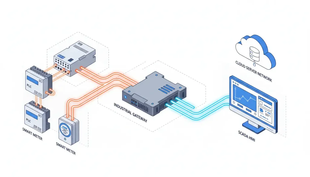
Whether integrating legacy CNC machines into modern SCADA networks or polling smart meters for energy management, Valtoris device servers provide reliable telemetry across a variety of OT topologies.
Wide Temperature Reliability
Achieve stable 24/7 operation in harsh cabinets with -40°C to 85°C industrial rating and 2KV surge protection.
Multi-Protocol Flexibility
More than transparent transmission. Natively handle Modbus RTU to TCP conversion and automatic Endianness byte-swapping at the edge.
Comprehensive Support
Enjoy peace of mind with OEM/ODM services, technical assistance, and warranty support. We don’t disappear after shipment.

High-Speed Performance
Serial baud rates up to 921.6 Kbps and 100M/1000M auto-sensing Ethernet interfaces. Telemetry throughput increases.
Scalable Port Options
Choose from 1, 2, 4, 8, 16, or 32-port models to match your network size. Desktop, DIN-rail, or 1U rack-mount for any installation need.
Isolation Protection
Models with 1500V–3000V optocoupler isolation completely block destructive stray currents and permanently eliminate RS485 ground loops.
Applications of Industrial Serial Device Servers
Discover how Valtoris converters enable reliable telemetry across harsh industrial environments.

Petrochemical & Oil Monitoring
Monitor pressure sensors at remote well sites. -40°C to 85°C operation with optical isolation guarantees safety in flammable cabinet zones.

Factory Automation & CNC
Connect legacy CNC machines, PLCs, and VFDs to Ethernet for centralized NC file downloads, remote diagnostics, and real-time monitoring.

Smart Energy & Substations
Collect inverter data from solar farms. Serial servers actively translate raw RTU metrics into Modbus TCP for centralized grid SCADA dispatch.

Smart Agriculture & Greenhouses
Aggregate 200+ sensors for temperature, humidity, CO₂ monitoring. Extend RS485 distance to 1,800m and expand to 256 nodes over the LAN.

Wastewater Treatment
Connect pH meters and flow sensors across kilometer-wide facilities. Replace manual inspections with real-time data across the central Ethernet backbone.

Building Management Systems
Integrate HVAC, lighting, and energy meters into centralized platforms. Eliminate RS485 distance limits for multi-floor monitoring.
What Our Clients Say
Real-world performance verified by industrial automation integrators.
“Tech support walked us through the Virtual COM setup and stayed on the line until our old Wonderware SCADA polled the LAN perfectly. That’s why we return.”
“We deployed Valtoris 8-port isolated servers across our VFD control panels. 3000V isolation completely stopped the stray voltage spikes that used to fry our comm cards.”
Industrial Serial Device Servers Related Resources
Explore practical wiring guides, cable pinouts, and Modbus communication architectures.

Expert Guides to Industrial Serial Device Servers
How Do I Choose the Right Serial Device Server for My Needs?
- Think about the port count (1 to 32), interface type (RS232, RS485, RS422, or mixed), and isolation requirements (1500V to 3000V for noisy environments).
- Need remote cloud connection? Pick models with MQTT.
- Do you need network redundancy? Versions with two Ethernet ports.
What Cost Benefits Do Valtoris Serial Servers Offer?
- Reduce cabling costs by sharing a single network connection with up to 32 devices.
- Minimize downtime with industrial-grade reliability.
- Eliminate field service calls through remote diagnostics.
- Lower inventory costs with multi-function devices that serve as serial servers, Modbus gateways and MQTT gateways.
What Customization Options Does Valtoris Offer?
- We offer OEM/ODM services such as custom firmware, baud rate customization, protocol support, modified enclosure designs and private labeling. Get in touch with our engineering team to discuss your exact requirements.
How Does Valtoris Provide After-Sales Support and Maintenance?
- With each purchase you will receive technical documentation, configuration software (VirCom) and web based setup guides.
- Our engineering team provides email and remote support. We offer warranty support and long term availability of products for re-orders.
Can this solve PLC polling collisions and Modbus Exception errors?
- Yes. Our true Modbus Gateways feature Smart Caching and Bus Decoupling.
- Instead of forcing your PLC to sequentially poll 30 slow RS485 devices, the gateway handles the micro-polling locally.
- Your PLC then reads the aggregated, continuous data instantly via a single Modbus TCP request.
Get a Direct Engineering Quote
Struggling to integrate legacy RS232/RS485 machinery into your modern TCP/IP network? Give us your exact port count and isolation requirements and our engineers will respond with a matched hardware quote within 2 hours.
Request Hardware QuoteFrequently Asked Technical Questions
Will converting RS485 to Ethernet introduce latency and cause my Modbus polling to time out?
A: Standard converters frequently cause timeouts because they wait too long to package serial frames into TCP packets. Valtoris servers eliminate this by providing customizable Frame Packing Thresholds (adjustable from 1 to 255 bytes, or 10ms to 1000ms intervals). This ensures strict Modbus RTU timing compliance across LAN networks.
What is the exact engineering difference between Transparent mode and Modbus Gateway mode?
A: Transparent mode simply chops raw serial bytes into TCP payloads without reading them. True Modbus Gateway mode actively inspects the protocol: it translates Modbus RTU frames into standard Modbus TCP headers. It also starts Slave Register Caching which allows two different SCADA masters to poll the same RS485 sensor simultaneously without bus collision exceptions.
My control room PC runs Windows 11 and has zero physical DB9 serial COM ports. How do I connect?
A: You install our free VirCom Virtual Serial Port driver. It captures the network IP stream and maps it to a virtual local port (e.g., COM5) inside Windows Device Manager. Your legacy software (like older Wonderware or WinCC builds) connects to “COM5” exactly as if a physical copper RS232 cable were strung 500 meters across the plant floor.
When is 3000V Optical Isolation strictly mandatory on an RS485 bus?
A: You must deploy isolated models (Series VI) whenever the RS485 data line crosses between two separate buildings, runs alongside 480V motor feeder cables, or enters Variable Frequency Drive (VFD) cabinets. Any difference in earth ground potential between distant buildings can cause destructive ground loop currents. Our internal 3000V optocouplers physically break that electrical path and protect your central IT switch gear.