

The RS485 standard has historically required a strict daisy-chain topology: a single unbroken bus terminated at both ends. But textbook conditions seldom exist in field installations.
Technicians often find existing cables pulled in a star configuration when retrofitting video surveillance, building automation (HVAC) or legacy factory floors.
That is where RS485 hubs come in. They help you work around the rules. Only when you really need to. RS485 hubs are useful when you have to deal with RS485. It is not working the way it is supposed to.
Table of Contents
- 1. The Two Wiring Topologies
- 2. What the RS485 Standard Says
- 3. When to Use Daisy Chain
- 4. When Star Makes Sense
- 5. Mixing Topologies Without a Hub
- 6. RS485 Reliability Analyzer (Tool)
- 7. How an RS485 Hub Solves It
- 8. Choosing the Right Hub
- 9. Wiring Tips & Stub Limits
- 10. Quick Reference
- 11. Frequently Asked Questions
Quick Field Check: What is your current wiring layout?
Select your physical topology to see the immediate signal risk.
Star vs. Daisy Chain: The Two Wiring Topologies
Daisy Chain (T-Connection)
This is the standard RS485 wiring method.
How it works: One main cable runs from the master to the farthest device. Every other device connects to this main line with a short stub (as short as possible).
Pros:
- Best signal integrity
- Supports longer distances
- Reliable at high baud rates
- Only one termination needed at each end
Cons:
- Can be awkward to wire in existing installations
- Adding a new device may require running cable from the nearest point
- Stubs must be kept very short
Star Connection
This is the wiring method used for most other cables—power, video, Ethernet.
In a star topology, each end-device is wired directly back to a master controller at the center, similar to standard Ethernet or power distribution layouts. This is very intuitive for physical installation, but it creates multiple parallel stubs on the RS485 bus.
Pros:
- Simple to understand and install
- Easy to add new devices
- Matches wiring of other systems
- Faults isolated to one branch
Cons:
- Uses more cable
- Not standard for RS485
- Can cause signal reflections if not handled properly (unless using an active RS485 Hub).
- No simple way to terminate
What the RS485 Standard Says
The RS485 standard, which is also known as TIA/EIA-485 says that devices should be connected in a line one after the other. This is called a daisy chain topology. The RS485 standard is pretty simple: it just needs one continuous cable and really short connections to each device.
Why does this matter? Long stubs and star branches create signal reflection per transmission line principles as described in the Texas Instruments RS-485 Design Guide. At higher baud rates or longer distances, these reflected waves collide with the original data stream, corrupting the digital pulses and causing intermittent timeout errors.
👇 Unsure if your current distance and speed will cause data errors? Use our quick calculator to check your physical limits instantly:
The standard was written for factory floors where you can route cables any way you want. It doesn’t account for the reality of retrofitting into buildings that are already wired in a star pattern. In our field deployments, we’ve seen video surveillance systems successfully use star-wired RS485 for up to 400 meters with about 10 devices—well beyond what the textbook allows.
When to Use Daisy Chain
Daisy chain is the right choice when:
- You’re designing a new system from scratch
- You need maximum distance or speed
- You have control over cable routing
- You’re experienced with RS485 termination
This is the “textbook” scenario. It will give you the best performance and fewest headaches.
When Star Makes Sense
Star wiring makes sense when:
- You’re retrofitting into an existing building
- Other systems (video, power) are already star-wired
- Simplicity of installation matters more than absolute performance
- Device counts are low and distances are moderate
While strict RS485 guidelines prohibit unterminated star branches, real-world field experience dictates otherwise. In legacy video surveillance (PTZ camera) retrofits, it is common to see low-speed RS485 control signals successfully running over star topologies for up to 400 meters with around 10 devices—relying entirely on the transceivers’ tolerance to mild signal reflections.
The Problem with Mixing Topologies Without a Hub
What if you have a large system with devices spread out? What if you need star wiring in some areas but daisy chain makes sense in others?
This is where the standard breaks down. You can’t just connect a star network to a daisy chain network and expect it to work. Signal reflections will cause intermittent failures. Curious about the exact electrical difference between building a star network from a low-cost terminal block vs an active, opto-isolated hub? Check out our technical comparison: Industrial RS485 Hub vs. Passive Splitter.
Field Troubleshooting: Is Your Topology Corrupting Data?
If you have intermittent CRC errors or ghost timeouts on a mixed topology, run these quick tests to check physical layer problems:
- The Multimeter Check: With the bus idle, measure the DC voltage between terminals A(+) and B(-). A good, properly biased RS485 line should have a stable differential voltage of at least 200mV (typically 2V to 3V). If it is bouncing around wildly or dropping to near zero you have severe signal reflection or a missing termination resistor.
- The Oscilloscope Check: Put a scope across A and B. Look for “ringing” (voltage overshoots and undershoots) when state transitions occur. If your square wave looks like the red trace in our diagrams above, your unterminated star branches are acting as antennas and destroying signal integrity completely.
RS485 Reliability & Solution Analyzer
Professional signal integrity analysis based on TIA/EIA-485 and Transmission Line Theory.
Analyzing…
Please adjust parameters to see results.
Engineering Solutions (When Copper Fails):
Eliminate EMI noise and ground loops entirely using Fiber Optics.
View FiberView Math & Physics Assumptions
Based on TIA/EIA-485 guidelines. Base Max Distance ≈
100,000,000 / Baud Rate.Multiplier: 24AWG = 1.0x, 22AWG Shielded = 1.5x, Unshielded Phone Cable = 0.7x.
2. Without Termination (Reflection Limit):
Not limited by attenuation, but by signal reflection (Transmission Line Theory). To prevent reflections from corrupting data, the propagation delay must be less than 10% of the bit time.
Approximated Limit ≈
300,000 / Baud Rate (meters). Beyond this threshold, the system fails regardless of wire quality. Margin is considered N/A.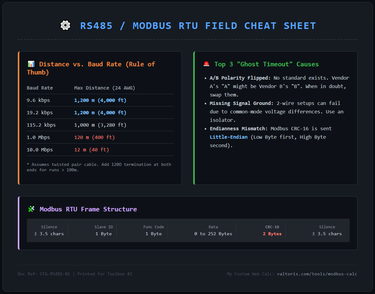
🛠️ Know Your Physical Limits (Offline PDF)
Unsure if your Star branches will cause data errors? Download our high-res RS485 physical layer cheat sheet. It includes the definitive Distance vs. Baud Rate table and top causes for ghost timeouts. Keep it in your toolbox.
Download High-Res PDFDirect download. No email required. Feel free to print it out and pin it on your server rack.
How an RS485 Hub Solves the Topology Puzzle
Thousands of dollars in labor and downtime can be spent rewiring an entire facility to the daisy-chain standard. A good active RS485 hub will act as a topology translator at a fraction of the cost. You can keep your existing star wiring, and perfectly isolate ground loops and regenerate the signal.
What the hub does:
- Signal regeneration: It doesn’t just pass the degraded signal through; it optically reads it and transmits a fresh, clean square wave, resetting your distance limit.
- Topology conversion: You can confidently connect a standard daisy chain to the main port and run star branches out of the sub-ports without cross-interference.
⚠️ The Hidden Danger of Star Networks: Ground Potential Difference
In factory retrofits or multi-building surveillance systems, devices on different star branches are almost always powered by completely different power sources. This creates a significant Ground Potential Difference. Connecting these remote devices directly via bare RS485 wires doesn’t just cause signal reflection—it forces high common-mode voltage spikes across the network.
An active RS485 hub solves this through Opto-isolation (typically up to 2500Vrms). It completely severs the physical electrical connection between branches. This feature is not just for signal clarity; it is a mandatory safeguard to prevent your expensive PLCs and transceivers from being permanently burned out by ground loop currents.
The hub becomes the central point that makes different topologies work together.
Other Reasons to Use a Hub
Exceeding the 32-Device Limit
RS485 drivers are typically rated for 32 unit loads. If you need more devices, a hub lets you add another segment.
Extending Distance
Hubs act as active repeaters. By receiving the degraded signal, optically isolating it, and transmitting a fresh square wave with a clean voltage swing, the physical distance limit is completely reset. Each cascaded port buys you another 1,200 meters (4,000 ft) of compliant transmission distance.
Rewiring an entire facility to meet the daisy-chain standard can cost thousands in labor. For a fraction of that cost, an active RS485 hub acts as a topology translator—allowing you to keep your existing star wiring while perfectly isolating ground loops and regenerating the signal.
🛑 Stop Fighting Signal Reflections
Mixing a Star topology into an existing Daisy Chain without an active Hub is a guaranteed recipe for “ghost timeouts” and data corruption. Don’t waste hours debugging bad wiring arrays.
- Regenerate Signals: Reset the 1200m distance limit on every branch.
- Force Compatibility: Connect T-junctions and Stars safely.
Choosing the Right Hub
Hubs come in different sizes and features. Here’s what to consider.
| Ports | Best For | Features to Consider |
|---|---|---|
| 2-port | Simple star conversion, small systems | Caching mode for dual-master applications |
| 4-port | Medium systems, mixing multiple stars | Isolation for ground break, baud rate range |
| 8-port | Large systems, many device clusters | Self-adaptive baud rate, high node count |
Port count: How many branches do you need? A 4-port hub can connect one master device (such as an Edge PC or Protocol Gateway) to three star branches, or act as a central point for multiple segments.
Isolation: If cables run between buildings or outdoors, get an isolated model. The 2500V isolation protects against ground loops and surges.
Baud rate range: Make sure the hub supports your communication speed. Most industrial hubs handle 1200 to 460800 bps.
Not sure which configuration fits your panel? Browse our [DIN-rail Isolated RS485 Hubs] to compare port layouts and specs.
Wiring Tips from the Field
Based on hundreds of factory deployments, here are the non-negotiable rules for hub wiring:
Keep stubs strictly minimized: Even in a hub-based configuration, drop lines (stubs) connecting the device to the main branch should be kept as short as physically possible (ideally less than 10% of the total cable length) to minimize localized signal reflection.
Use shielded twisted pair. This is really important when you are outside or in a factory. The wires are twisted together which helps stop signals from getting in the way. The shield that is, around the wires also helps block these signals.
Ground the shield at one end only. Connect the shield to ground at the hub side, leave it floating at the device side. This prevents ground loops.
Terminate properly. In a star network it is not possible to terminate every branch. The hub is responsible, for handling the quality of the signal on its own. If you are using a combination of network topologies you should follow the instructions provided in the hubs manual to properly terminate the connections.
Quick Reference: When to Use What
| Scenario | Recommended Approach |
|---|---|
| New installation, clean slate | Daisy chain |
| Small retrofit (<10 devices, <400m) | Star directly (empirical limit) |
| Mixed topology needed | Hub at central point |
| More than 32 devices | Hub to add segments |
| Different ground potentials | Isolated hub |
A Final Thought
RS485 is a standard that works well when you use it correctly. In real life things are not always perfect like they are in books. A hub helps you make RS485 work for your building instead of making your building work for RS485.
You should pick a hub that has the number of ports and can keep things separate like it is supposed to. If you wire it up carefully it will last for a time. When you are looking at options, look for things that are built for industrial use: wide temperature tolerance, DIN-rail mounting readiness, and proper galvanic isolation. Companies like Valtoris have a lot of options that have these features.
*Note: This guide references the TIA/EIA‑485 standard and practical experiences from the field. Always consult your device manuals for specific wiring requirements.*
Frequently Asked Questions
Can I use a cheap passive splitter (T-junction) instead of an active RS485 Hub?
Does it matter which port I connect the master PLC to?
How do I handle termination resistors in a Hub-based Star network?
Can I use standard Cat5/Cat6 Ethernet cable for RS485 wiring?
Can I exceed 32 devices if I use “1/4 load” or “1/8 load” RS485 transceivers?
TALK TO A CONNECTIVITY ENGINEER
Are CRC errors on your factory floor caused by signal reflections from an uncontrolled Star topology? If you drop your current wiring array below, our team can help you spec the exact Hub routing needed to stabilize the bus.
