
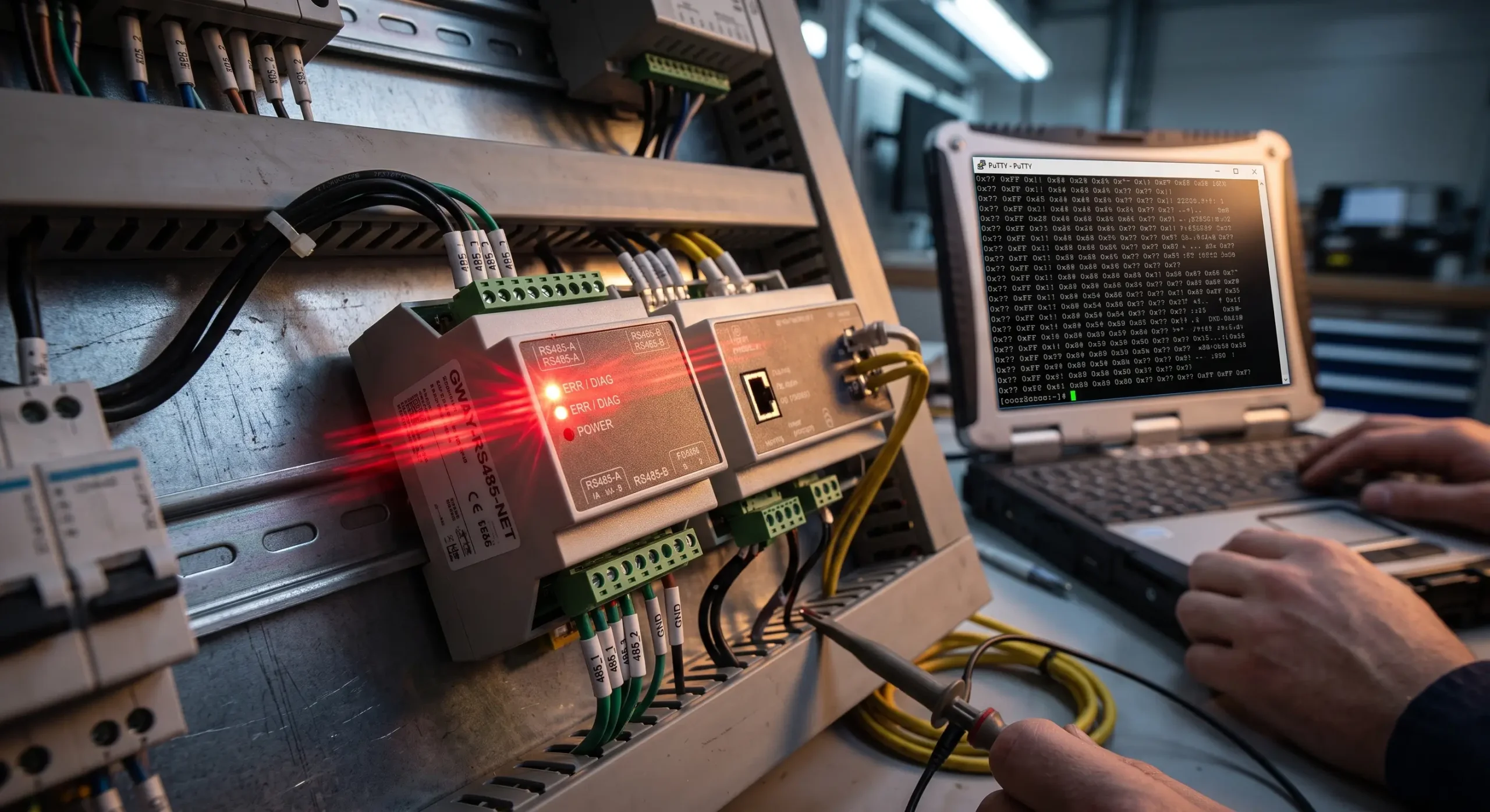
One of the most common critical errors in industrial network upgrades is integrating multiple control systems. A field device ( VFD , power meter , etc . ) will typically talk just fine to a single local HMI , with fast polling and reliable data . However, wiring a second SCADA system from a central control room to pull data at the same time often causes the whole network to collapse. Configuring Modbus RTU multiple masters on a single serial bus creates instant architectural conflicts.
This failure is quickly indicated by system indicators: fault alarms are displayed on monitoring screens, and data values go to zero. Serial network analysis does not reveal any clean modbus frames. Instead the bus shows direct consequences of RS485 Data Collisions: scrambled data packets, constant CRC checksum failures and persistent Exception Code 0x0B errors.
Common troubleshooting tasks include checking A/B wiring polarity, 120 Ohm termination resistors or baud rates. But if the network works well with one master and fails with another one, then the baseline is already correct in the physical wiring. The underlying problem is not a wiring error but an inherent limitation in the architecture of the Modbus RTU protocol.
Figure 1: Typical footprint of an RS485 collision—garbled return packets followed immediately by CRC failures and 0x0B timeouts.
🔍 Interactive Guide: Diagnose Your Network Crash
Select the exact symptom occurring on your factory floor to skip directly to the architectural solution.
Quick Navigation Guide
The Hard Truth: Why Modbus RTU is Strictly Single-Master
To fix the collision, the physical layer constraints must be evaluated. Modbus RTU was explicitly designed for the EIA/TIA-485 standard (commonly known as RS485), which operates on a differential 2-wire copper bus.
Based on the Modbus over Serial Line Implementation guidelines, the protocol operates strictly on a Master-Slave architecture. At the hardware level, the RS485 electrical standard is inherently Half-Duplex. This creates a single-lane transmission path where only one electrical signal can occupy the copper wires at any given microsecond.
Unlike the modern Ethernet networks that use CSMA/CD (Carrier-Sense Multiple Access with Collision Detection) as defined by the IEEE 802.3 Ethernet Standard to coordinate simultaneous traffic, the legacy serial layer does not really have any native rs485 collision detection mechanisms. It is a passive layer of the physical. Because there is no true native rs485 multi master protocol built into the standard, initiating a Modbus RTU multiple masters polling sequence means there is no way for the bus to prevent transmission overlap.
When Master A (HMI) and Master B (SCADA) pull data at the exact same millisecond, their digital square waves physically overlap on the copper wire. The destination slave device receives an unrecognizable mess of high and low voltages. It fails the cyclic redundancy check (CRC) and simply drops the packet, remaining completely silent.
Diagnosing RS485 Bus Contention: CRC Errors and Silent Drops
Before throwing hardware at the problem, you must confirm that bus contention is the actual root cause. A true multi-master collision leaves very specific diagnostic footprints on your network hardware and software logs.
| Diagnostic Symptom Observed | Root Cause in a Multi-Master Network |
|---|---|
| Gateway TX LED blinks rapidly, RX LED stays dark. | The gateway sent the SCADA’s request, but the packet collided on the wire. The slave ignored the corrupted data and sent nothing back (Silent Drop). |
SCADA log shows Exception Code 0x0B. | Target Device Failed to Respond. The SCADA software timed out waiting for the reply that was destroyed in the collision. |
HMI screen values briefly flash to 0 or ####. | Intermittent collisions causing consecutive dropped packets, forcing the HMI to display fallback empty data. |
| System runs fine for 2 hours, then crashes wildly for 10 minutes. | “Ghost Collisions” caused by time-staggered polling timers overlapping due to internal clock drift (explained below). |
Software Hacks vs. Reality: Why Time-Staggered Polling Fails
When programmers encounter these collisions they generally try to work around the hardware problem with software solutions. The most popular “hack” is Time-Staggered Polling (offset timers).
The logic appears sound: Program the local HMI to poll the network at Second 0, Second 2 and Second 4. Program the SCADA to poll on Second 1, Second 3 and Second 5. In theory they take turns and there are no collisions.
In reality, this fails disastrously in industrial environments due to Oscillator Clock Drift. Industrial PLCs and HMIs use standard quartz crystal oscillators. These crystals are affected by ambient temperature and aging, typically deviating by about 20 to 50 ppm (parts per million). Over time, “Second 1” on the HMI and “Second 1” on the SCADA will slowly creep toward each other until they violently overlap.
⏱️ PLC Clock Drift Collision Predictor
Enter your polling offset to see how quickly hardware clock drift will destroy your carefully timed software sequence.
Calculating…
As the calculator proves, within a matter of days or weeks, the timers will overlap. You will experience random, unexplainable data drops that vanish as quickly as they appear. Software cannot fix a physical layer limitation.
| Workaround Method | How it Works | Why it Ultimately Fails |
|---|---|---|
| Time-Staggering | Master A and B are programmed to poll at different intervals. | Hardware clock drift causes timers to overlap, resulting in intermittent, hard-to-diagnose ghost crashes. |
| Increasing Timeouts | Changing SCADA timeout from 500ms to 3000ms to survive a crash. | Introduces massive latency. If a collision happens, the entire SCADA freezes for 3 seconds waiting for a dead packet. |
| Master-Relay (PLC Code) | Master A polls slaves; Master B is reprogrammed to poll Master A. | Consumes immense PLC CPU cycle time, requires source-code access, and vastly complicates the ladder logic. |
The Hardware Fix: Deploying a Smart Caching Hub
The definitive engineering solution to multi-master contention on a pure serial network is to sever the physical connection between the masters and deploy an active Buffered Caching Hub.
A smart caching hub (also known as an active Modbus serial multiplexer, such as the Valtoris 2CH-HUB-RS485) fundamentally alters the network architecture. It is not a passive wire splitter. It acts as an independent, highly intelligent “Super-Master” on the downstream side…
, and a high-speed data server on the upstream side.The “Middleman” Memory Buffer
When configured, the Hub takes over the sole responsibility of polling the underlying RS485 slave devices (like your VFDs). Because it is the only master on that specific bus segment, physical collisions are mathematically impossible. It continuously pulls the data and stores it inside its internal high-speed RAM.
When your Local HMI (connected to Hub Port 1) and your Central SCADA (connected to Hub Port 2) request data at the exact same millisecond, the Hub does not forward these requests down to the slow serial bus. Instead, it instantly retrieves the requested registers from its RAM and replies to both masters concurrently.
| Feature | Standard RS485 Repeater / Splitter | Active Smart Caching Hub (2CH-HUB) |
|---|---|---|
| Data Processing | Passive (Dumb). Amplifies electrical signals blindly. | Active (Smart). Reads Modbus frames and caches data. |
| Collision Handling | Fails. Amplifies the collision, crashing the whole network. | Flawless. Isolates masters into separate collision domains. |
| Response Latency | High (Bottlenecked by the 9600bps slave device). | Ultra-Low (<3ms). Data served instantly from onboard RAM. |
| Baud Rate Conversion | Usually requires all ports to run at identical speeds. | Self-adaptive. HMI can run at 115200bps while the VFD runs at 9600bps. |
Handling Modbus Write Commands (Conflict Detection)
Data Acquisition (read): Caching is great. But what if the SCADA is trying to write the VFD frequency with a Modbus write command (Function 0x06) and the HMI is trying to write too? The Hub has RS485 Conflict Detection & Arbitration. It stores one command in a temporary buffer, waits until the bus reaches absolute idle time (e.g. 20ms silence) and injects the commands one by one. No data lost, no packets crash.
For example, if you are overriding a critical speed setting or sending a stop command, the FIFO queue adds a maximum delay of one Modbus frame cycle (typically 15 to 25 milliseconds at 9600 bps). 99% of process controls and PLCs are not bothered by this microsecond delay, and it poses no threat to machine safety.
Advanced Architecture: What if Your SCADA Uses Ethernet?
The 2CH-HUB-RS485 is the ultimate solution when your HMI and SCADA are both relying on pure serial RS485 cables. However, as facilities modernize (Industry 4.0), you may be upgrading your central SCADA to operate over a high-speed Ethernet (TCP/IP) backbone, while keeping the legacy RS485 sensors on the factory floor.
If you connect multiple Modbus TCP clients to a standard “transparent” Ethernet-to-Serial converter, you will face the exact same collision problem. The transparent gateway will dump multiple concurrent TCP requests onto the half-duplex serial line, causing a crash.
| Network Environment | Master Architecture | Recommended Valtoris Solution |
|---|---|---|
| Pure Serial (Legacy) | HMI (RS485) + SCADA (RS485) | 2CH-HUB-RS485 (Serial Caching Hub) |
| Mixed IT/OT (Modern) | Local HMI (TCP) + Cloud Historian (TCP) | 16-Port Storage Modbus Gateway |
To solve Ethernet-based multi-master collisions, you must deploy a Storage Modbus Gateway. Much like the caching hub, devices like the Valtoris 16-Port Gateway utilize a massive 10K internal cache to decouple the high-speed Ethernet queries from the slow serial bus, effortlessly supporting up to 30 concurrent TCP socket clients without a single collision.
How Storage Gateways Strip the MBAP Header
Unlike transparent converters that blindly stuff serial bytes into TCP packets, a true Storage Gateway acts as a bilingual translator. Modbus TCP requires a 7-byte MBAP (Modbus Application Protocol) header and relies on the Ethernet TCP/IP layer for error checking. Modbus RTU requires a 1-byte Slave ID and a strict 2-byte CRC checksum at the end.
A standard transparent gateway will pass an RTU CRC into a SCADA system that is expecting an MBAP header, causing a fatal format error in the SCADA logs. A Storage Gateway actively strips off the TCP MBAP header, calculates the RTU CRC checksum on the fly and translates the protocol flawlessly. Your SCADA will receive clean, standardized TCP data.
The 3-Millisecond TCP Response Mechanism
In a large facility with a 16 port gateway the internal processor maps the holding registers of the entire factory floor into the local memory of the device. If both your Cloud Historian and Local SCADA want 100 registers, the gateway can answer straight off DDR RAM. The response time over Gigabit Ethernet is reduced to less than 3 milliseconds.
This edge-caching architecture eliminates polling lag and network timeouts and securely connects the OT (Operational Technology) serial floor to the IT (Information Technology) enterprise network without having to rewrite a line of PLC code.
Technical Specifications: Valtoris Industrial Caching Hub
| Specification | 2CH-HUB-RS485 Data |
|---|---|
| Port Configuration | 2 x Master Ports (Input) / 1 x Slave Trunk (Output) |
| Core Technology | Smart Caching, Address Filtering, FIFO Queuing |
| Supported Protocols | Modbus RTU, Modbus ASCII |
| Baud Rate Range | 300 bps to 115,200 bps (Independent per port) |
| Response Time (Cache) | < 5 milliseconds |
Stop gambling your facility’s uptime on software delays and time staggering hacks. By attacking the collision on the physical level with an active caching hub the bus contention is removed forever and deterministic data delivery is guarantyd for several control systems.
Frequently Asked Questions (Field Integration)
Q1: Can I use a standard RS485 repeater to solve multi-master collisions?
No. A standard repeater operates strictly at the physical layer to amplify voltages and extend cable distance. It has no memory or protocol awareness. If two masters transmit at once, the repeater will simply amplify the collided, corrupted signal, ensuring the network crashes even harder.
Q2: Will increasing the baud rate from 9600 to 115200 bps prevent data collisions?
Higher baud rates reduce the time a packet spends on the wire, and therefore statistically reduce the frequency of collisions. But it does not resolve the architectural problem. If the bus is still half duplex, simultaneous polling from two masters will still lead to 0x0B exceptions inevitably.
Q3: How does the caching hub handle Modbus write commands (e.g., Function 05 or 06) if it relies on a memory buffer?
The caching hub performs protocol inspection. It responds to Read commands right from its buffer, and detects Write commands, actively routing them to the physical slave. If multiple writes come in at the same time, the hub’s FIFO (first-in first-out) logic puts them in a queue and maintains a rigid idle period between transmissions to prevent collisions at the physical layer.
Q4: My system uses 4-wire RS422. Do I still need a caching hub for multiple masters?
While RS422 is full-duplex (separate transmit and receive pairs), which prevents electrical collisions on the wire itself, slave devices generally cannot process multiple Modbus protocol queries simultaneously. You still require a caching device to act as an arbitrator, queuing the requests so the slave is not overwhelmed.
Q5: Does implementing the 2CH-HUB-RS485 require reprogramming my PLC ladder logic?
No, it requires zero changes to your existing code. Because the hub actively caches and serves identical Modbus frames, the integration is completely transparent to your SCADA and PLC. You can remove all complicated time-staggering code from your logic.
Eliminate RS485 Collisions Permanently
Stop debugging software timers and battling clock drift. Upgrade to industrial Smart Caching Hubs and Storage Gateways to physically isolate your master nodes.
