
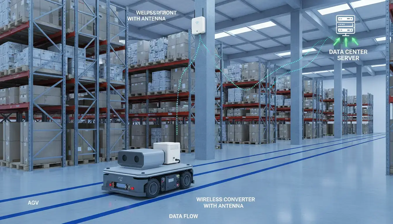
In our experience across hundreds of factory retrofits, more than 65% of industrial equipment still uses RS232 or RS485. But in retrofit projects, up to 60% of the time, structural problems make it impossible to run new cable. Your factory has a PLC on the floor, a power meter hidden away in an electrical room, or a sensor on a crane. They need to send data, but they can’t drill through concrete and wait days for construction workers to show up. An RS485 to WiFi converter is the answer when you can’t wire. No new conduit. No digging. Only data over the air.
Here’s how to bypass the physical barriers, choose the right setup, and avoid the common network traps.
- Three Ways to Deploy an RS485 to WiFi Converter
- 1. Remote SCADA Integration (STA Mode)
- 2. Localized PLC Debugging & Maintenance (AP Mode)
- 3. Point-to-Point Wireless RS485 Bridging (Transparent Mode)
- The “Transparent” Converter Trap: TCP vs. True Modbus Gateways
- Bridging to Legacy Software: The Virtual COM Port Solution
- Phantom Disconnects: Why Your Module’s “Green Light” is Lying
- IT/OT Security: Securing Unencrypted RS485 over WiFi
- The Direct-to-Cloud Myth: Why Standard WiFi Fails at MQTT
- Frequently Asked Questions
| What you’re trying to do | Most likely fit | Recommended Focus |
|---|---|---|
| Pull data from meters or sensors in hard-to-reach spots | Remote monitoring | STA Mode & Cloud |
| Debug a PLC without running back to your desk | On-site debugging | AP Mode Direct Link |
| Keep moving equipment (AGVs, cranes) connected | Mobile equipment | Industrial Roaming |
| Fix garbled data and dropped packets | Troubleshooting | Shielding & Parameters |
Three Ways to Deploy an RS485 to WiFi Converter
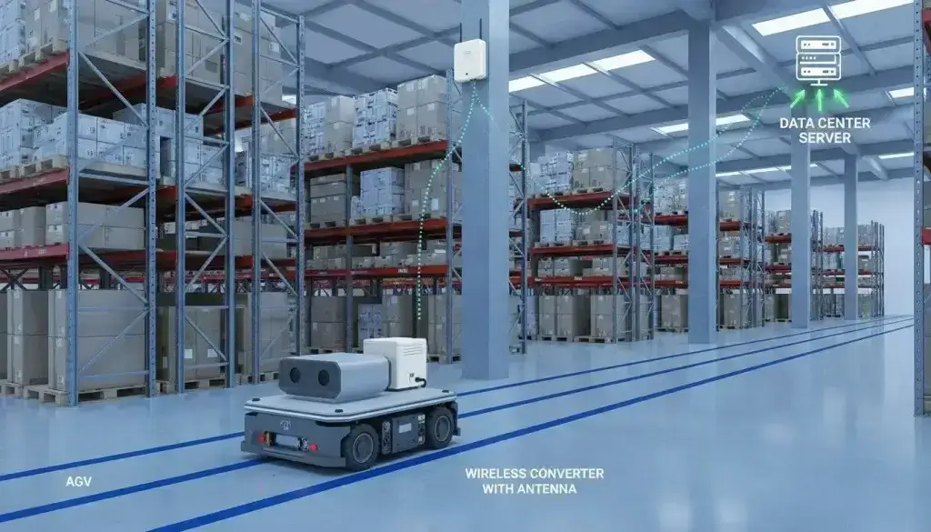
To successfully integrate legacy serial devices into modern wireless networks, you must select the correct operational mode based on your physical constraints and software requirements. Before exploring the three primary deployment architectures, it is crucial to understand how the two primary WiFi modes function.
| Mode | AP Mode (Access Point) | STA Mode (Station) |
|---|---|---|
| Who creates WiFi | The converter itself | Your existing router/network |
| Who connects | Your laptop/phone connects to it | Converter connects to your network |
| Range | Short (30-50 meters indoors) | As far as your WiFi infrastructure reaches |
| Best for | Debugging, temporary connections | Permanent installs, cloud sending |
1. Remote SCADA Integration (STA Mode)
Legacy power meters can be physically challenging to retrofit across a large factory floor. It’s too expensive to trench concrete or run new conduit. You can install an RS485 to WiFi converter at each meter, using the existing factory 2.4GHz network (STA Mode), to aggregate real-time energy telemetry to a central SCADA server, without stopping production for cable installation.
But STA mode is not just for stationary meters bolted to a wall; it is the same architecture used to solve the moving equipment problem.
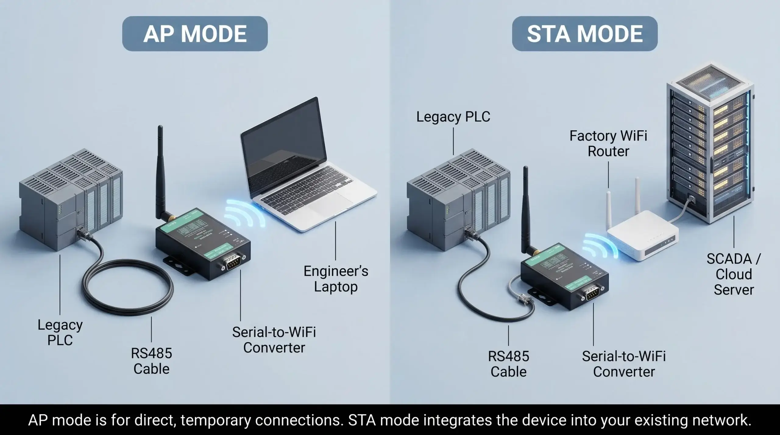
Scenario: Mobile Equipment & AGVs (STA Mode Roaming)
Hardwiring is impossible for Automated Guided Vehicles (AGVs) and overhead cranes. Moving is constrained by trailing cables, slip rings wear out. The equipment moves through the facility while a small wireless converter, operating in STA mode, remains plugged into the factory’s WiFi access points, sending real-time coordinate and battery data back to the central control system as easily as a hardwired serial port.
2. Localized PLC Debugging & Maintenance (AP Mode)
Routine maintenance on factory floor PLCs shouldn’t require running 50-foot Ethernet cables across walkways. This is where a converter’s AP (Access Point) Mode is invaluable. Engineers can connect their laptops directly to this localized network to push code updates or read diagnostics while standing next to the machine—bypassing the plant’s main IT infrastructure entirely.
3. Point-to-Point Wireless RS485 Bridging (Transparent Mode)
When you want to replace a long cable between two distinct serial devices (e.g., a master PLC and a remote sensor), you don’t need a complex network—you need an invisible wire. This is achieved by pairing two converters together (One in AP mode, one in STA mode) to form an exclusive RF bridge.
To bridge devices successfully, follow this strict setup sequence:
- Wire it: RS485 A to A, RS485 B to B. GND is optional but recommended for long runs.
- Power it: 9-24V DC. Industrial panels usually have 24V.
- WiFi Layer Setup: Set Module 1 to AP Mode (creates the WiFi network). Set Module 2 to STA Mode and connect it to Module 1’s SSID.
- Protocol Layer Setup (Critical): Set Module 1 as TCP Server. Set Module 2 as TCP Client and point its Destination IP to Module 1’s IP address.
- Match Serial Parameters: Ensure Baud rate, Data bits, and Parity match exactly on both sides. This is where 80% of bridges fail.
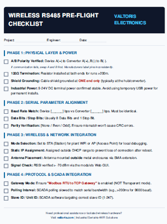
⚠️ The “Phantom Disconnect” Defense Guide
Don’t let mismatched baud rates or missing termination resistors ruin your setup. Download our offline field guide to troubleshoot ghost timeouts and verify parameters before powering up on a live factory floor.
Download Field Guide (PDF) * No email required(If you are strictly doing a P2P bridge, refer to our deep-dive Point-to-Point Wireless RS485 Configuration Guide for exact parameter mapping).
The “Transparent” Serial to WiFi Converter Trap: TCP vs. True Modbus Gateways
A lot of devices that use RS485 can talk to each other using Modbus RTU. However, a common mistake engineers make is buying a cheap “transparent” serial to WiFi converter and expecting their modern SCADA system to read the data instantly.
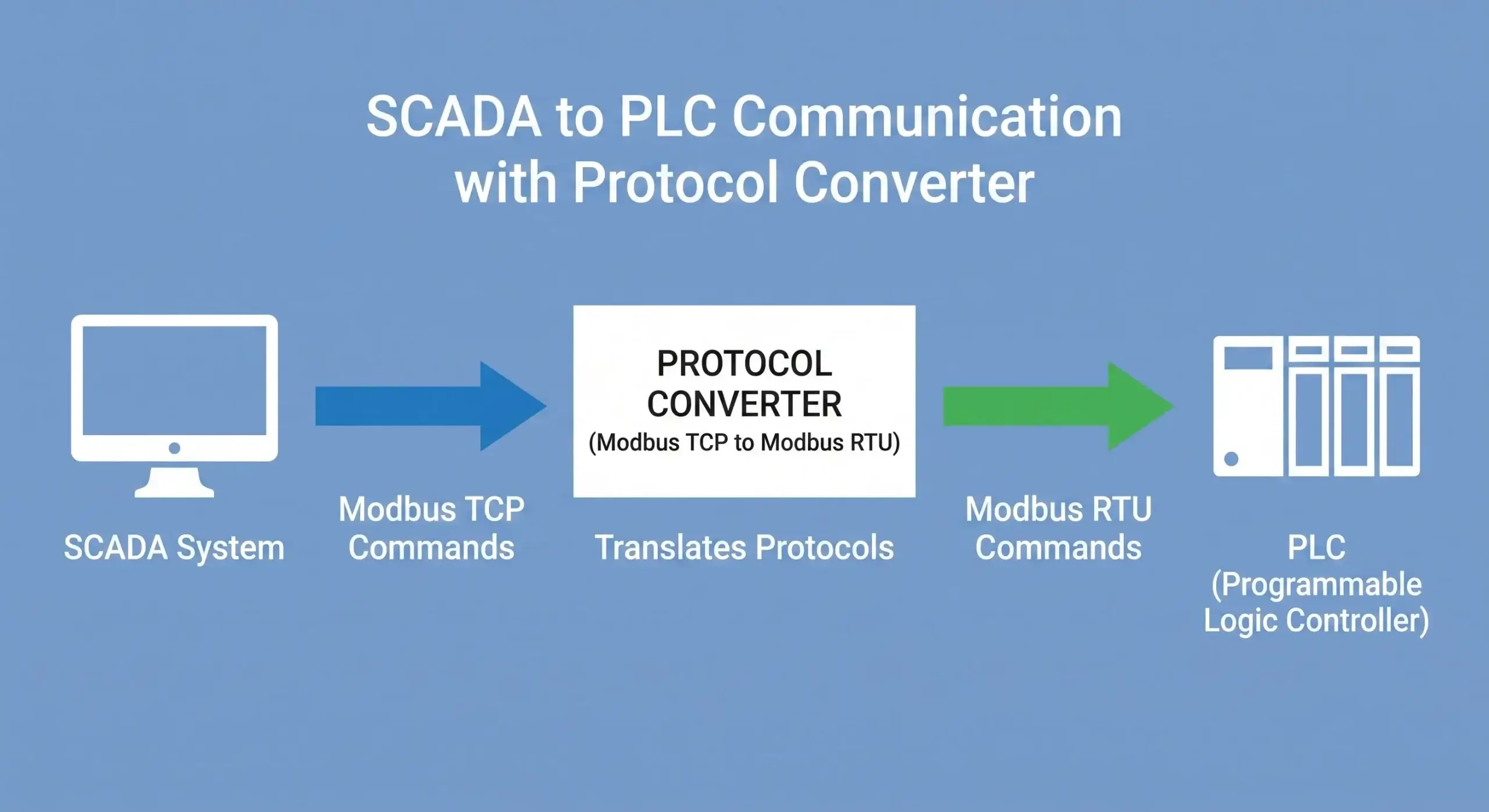
Transparent converters simply take the raw RS485 serial bits and shove them into a TCP packet. If your SCADA software is strictly looking for standard Modbus TCP protocol over port 502, it will reject these transparent packets because the framing and error-checking headers don’t match.
Wireless Modbus RTU is used by a lot of field devices. To fix this, you need a serial-to-WiFi converter with a Modbus gateway built in that works as a real protocol translator. The good news is that Modbus RTU works well with industrial-grade converters.
- Your SCADA or cloud platform sends Modbus TCP to the converter’s IP address.
- The converter translates the packet to Modbus RTU and sends it out the RS485 serial port.
- The device responds, and the converter translates back.
Modbus TCP vs RTU Packet Simulator
Watch exactly why transparent dongles drop SCADA connections.
✅ Connection Verified. Zero Timeout Errors.
Hardware-level Modbus caching guarantees deterministic responses.
View Industrial Gateway Specs →Bridging to Legacy Software: The Virtual COM Port Solution
Earlier, we mentioned using AP mode to debug a PLC locally. However, there is a catch that often frustrates engineers: legacy industrial programming software (like early versions of Step7, GX Developer, or older SCADA tools) completely ignores IP addresses. These applications are hardcoded to communicate exclusively through physical COM ports (e.g., COM1, COM2).
To close this gap over a wireless network, you must utilize Virtual COM Port software. This utility installs on your laptop or server and creates a simulated RS232/RS485 port in Windows Device Manager. The software listens to the data coming out of that virtual port and seamlessly redirects it over Wi-Fi to the IP address of your wireless converter.
As far as your legacy software is concerned, it believes it is plugged into a hardwired serial cable, allowing you to flash firmware or read telemetry over the air without rewriting a single line of legacy code.
Phantom Disconnects: Why Your Module’s “Green Light” is Lying
You walk up to the panel, the power LED is on, and the WiFi LED shows a connection. But your SCADA screen says “COM Loss.” Why? WiFi works great in an office. Factories are harder.
Engineers frequently encounter phantom disconnects caused by physical layer issues.
| Challenge | Why It Happens | Engineering Fix |
|---|---|---|
| Signal blocked | Metal cabinets act as Faraday cages | External antenna, mounted outside cabinet |
| Interference | Motors, VFDs, welders | Industrial shielding, metal enclosure |
| Crowded 2.4GHz | Phones, Bluetooth, microwaves | Switch channels or step up to 5GHz |
| Logic lockups | Voltage spikes, packet loss | Hardware Watchdog Timer (Auto-reboot) |
To survive, you cannot use a plastic dongle. The IEEE and ISA emphasize that industrial networking equipment must meet stricter environmental specifications—including wider temperature ranges (-40°C to 85°C), EMI shielding, and surge protection—to maintain reliability.
Good converters automatically reconnect. They keep trying until they’re back online. If your module locks up from electrical noise and requires a manual power cycle, it lacks a proper hardware watchdog timer—a mandatory feature for industrial resilience.
IT/OT Security: Securing Unencrypted RS485 over Factory WiFi
One of the biggest roadblocks to implementing wireless serial communication is the IT department. Traditional RS485 data (like Modbus RTU) is transmitted in clear text. If a cheap converter broadcasts this data over an open or weakly protected Wi-Fi network, anyone with a packet sniffer can intercept your machine telemetry or, worse, inject malicious control commands into the PLC.
To bridge the IT/OT divide securely without overcomplicating the network, industrial wireless converters rely on isolated physical-layer security and strong standard encryption:
- WPA2-PSK (AES) Encryption: Ensures that the data payload traveling through the air is mathematically scrambled and protected from standard wireless interception tools.
- Hidden SSIDs: When configuring the module in AP mode, you can hide its network footprint so it does not even appear on a smartphone or unauthorized laptop’s Wi-Fi scan.
- Air-Gapped AP Networks: By using the Point-to-Point (AP to STA) topology discussed above, your serial data never touches the factory’s main IT infrastructure or the internet, completely eliminating remote cyber-attack vectors.
The Direct-to-Cloud Myth: Why Standard WiFi Converters Fail at MQTT
Many engineers attempt to send RS485 data directly to AWS or Azure using standard serial-to-WiFi converters. This often leads to failure. Enterprise cloud platforms demand Secure MQTT (MQTTS) encrypted via TLS 1.2 or higher. Standard commercial WiFi converters simply lack the CPU power and memory to process 2048-bit certificate handshakes.
• For Local SCADA: Use a standard RS485 to WiFi Converter (like VT-WF100) to translate Modbus RTU to Modbus TCP and send it to your local server.
• For Direct-to-Cloud: You must step up to an Industrial Cellular Router designed with the processing power to handle embedded TLS certificates natively.
Serial to WiFi is for when you can’t run cable. You have to consider signal strength, interference, and power. But when wired is not an option, choosing an industrial-grade wireless converter with true Modbus parsing and a solid hardware watchdog is the definitive solution. Set it up one time properly. Then let it run.
Frequently Asked Questions
Will adding an RS485 wireless bridge cause Modbus polling timeouts in my SCADA?
Can I daisy-chain multiple RS485 devices behind a single WiFi converter?
Do I need a static IP for the RS485 to WiFi converter, or can I use DHCP?
Can the Virtual COM Port software connect to a WiFi converter that is on a different subnet?
Do I need an isolated RS485 port for wireless setups?
Stop Letting Wiring Constraints Dictate Your Network
Whether you need AP-mode for PLC debugging or a Modbus Gateway for SCADA integration, specify the right hardware the first time.
1. Select the Right Form Factor
For legacy CNCs requiring a DB9 RS232 port, review the VT-WF100. For control cabinets needing standard 35mm DIN-rail mounting and RS485 terminals, specify the VT-WF110.
2. Consult Engineering
Getting “COM Loss” errors? Describe your PLC and SCADA setup below. We’ll diagnose the physical layer.
Submit Diagnostics →Talk to a Connectivity Engineer
Tell us about your wireless project. We’ll spec the right architecture within 24 hours.
