

Sending a dry contact over ethernet is the most cost-effective way to transmit remote signals—such as pump relays, leak sensors, or door contacts—across long distances without pulling dedicated copper cables. This physical wiring is expensive, labor intensive, and subject to electromagnetic interference (EMI).
The alternative that is the industrial standard is to digitize the open/close status at the edge and send this contact closure over ethernet using your existing IP network infrastructure.
This article describes the physical wiring requirements of passive dry contacts, explains three common integration architectures (P2P Mirroring, Modbus TCP for SCADA, and MQTT for IoT), and the basic hardware specifications for choosing an industrial Ethernet I/O module.
- Why Extend Dry Contacts Over Ethernet? (The Architectural Shift)
- The Physical Challenge: Powering a “Dead” Switch
- Scenario 1: Peer-to-Peer (P2P) Contact Mirroring
- Scenario 2: Bringing Dry Contacts into SCADA & PLCs (Modbus TCP)
- Scenario 3: The Cloud Jump (Bridging OT and IT via MQTT)
- The Hidden Pitfalls of Ethernet I/O (And How to Avoid Them)
- Final Thoughts: Engineering Your Network for Scale
Why Extend Dry Contacts Over Ethernet? (The Architectural Shift)
Before discussing the network protocols, it is important to understand the architectural change from the traditional hardwired network to decentralized IP network. Hardwiring a remote dry contact requires running multi-core shielded instrument cable (like Belden 8760), installing conduit, and dealing with physical point-to-point connections all over a facility.
Today’s industrial design moves away from that physical centrality. The dry contact signal is digitized at the edge, enabling facilities to route simple open/close states as TCP/IP packets over existing Local Area Network (LAN), fiber backbone or cellular infrastructure.
| Architecture Factor | Traditional Copper Hardwiring | IP-Based Network Topology |
|---|---|---|
| Infrastructure | Requires dedicated physical conduits and copper lines. | Leverages existing Ethernet/Wi-Fi/Cellular networks. |
| Deployment Time | Days (Trenching, pulling, and terminating wire). | Hours (Edge digitization and IP configuration). |
| Scalability | Rigid. Adding a new sensor requires pulling a new cable. | Highly flexible. Add virtual digital nodes on demand. |
| Signal Integrity | Vulnerable to voltage drop over long distances and EMI. | Flawless digital transmission over any distance. |
The Physical Challenge: Powering a “Dead” Switch
Once the decision is made to utilize an IP network instead of pulling copper, engineers run into an immediate hardware hurdle: bridging the gap between the physical and digital worlds.
The biggest roadblock IT professionals face is understanding the electrical nature of a dry contact. A dry contact (like a relay switch or a magnetic door contact) has no voltage of its own. It is simply a mechanical bridge that opens or closes. You cannot plug it directly into a network router or ethernet switch.
To read its state, a small sensing voltage—known as wetting voltage—must be sent through the contact to detect whether the circuit is closed.
How do you get this voltage without messy external power supplies? If you are looking for an Ethernet I/O module, make sure that it has native support for passive switching. For example, advanced modules support a direct connection of the dry contact between the DI (Digital Input) and GND terminals. The module provides the internal voltage loop automatically, simplifying your wiring diagram and saving installation time.
After the physical dry contact is wired correctly and digitized by the Edge I/O module, the question then becomes: Where does this signal need to go? Depending on the infrastructure of your facility , there are three primary methods for routing this data across your IP network . Let’s take a look at them, starting with the simplest.
Scenario 1: Peer-to-Peer (P2P) Contact Mirroring (No PLC Required)
The Need: You want a high-water float switch at Tank A to directly turn on a pump relay at Station B, 5 miles away. You do not want to buy a PLC, and you do not know how to write ladder logic.
The Ethernet Solution: P2P Contact Mirroring to a remote ethernet relay switch.
By deploying two Ethernet I/O modules on the same network (or across a VPN/Cellular network), you can configure them to mirror each other. Module A acts as the Client reading the dry contact. As soon as the contact closes, Module A actively sends a command over the network to Module B (the Server), telling it to close its local relay output (DO).
💡 In Plain English: Think of P2P Mirroring as an “invisible, infinitely long wire.” When the float switch at Tank A moves, Module A immediately calls Module B over the network and says, “Turn on the pump!” No programming, no master PLC, and no complex servers needed—just two smart boxes talking directly to each other.
| Step | Module A (Input Site) Configuration | Module B (Output Site) Configuration |
|---|---|---|
| 1. Network Role | TCP Client | TCP Server |
| 2. Target Routing | Set Destination IP to Module B’s IP | Listen on Local Port (e.g., 502) |
| 3. Logic Binding | Enable “Active Report” upon DI change | Receive Modbus command and actuate Relay |
The Secret to “No Programming”: DI Active Report
How does Module A know to send a command without a PLC running code? Industrial edge nodes (like the Valtoris series) feature a built-in firmware function called DI Active Report.
Using the included Vircom configuration utility, you simply enter Module B’s IP into the DI report addr field. When the contact closes, the hardware handles the Modbus ‘Force Coil’ logic internally. Zero ladder logic required.
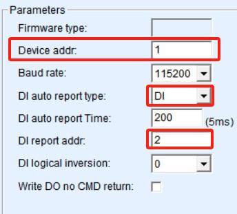
Figure 2.1: Valtoris Vircom Utility. Simply setting the “DI report addr” targets the destination module, replacing hours of PLC ladder logic programming.
Scenario 2: Bringing Dry Contacts into SCADA & PLCs (Modbus TCP)
The Need: Automation engineers need to read the status of 8 remote dry contacts into an existing Allen-Bradley, Siemens PLC or SCADA system (like Ignition or Wonderware) for central monitoring.
The Ethernet Solution: Deploying a dedicated Modbus TCP digital input module at the edge.
Instead of pulling 8 pairs of copper wire all the way back to the main PLC’s input card, you put the Ethernet I/O module right next to the dry contacts. The module reads the physical open/closed states and automatically maps them to the standard internal memory registers.
The edge I/O node can be integrated without any changes, working as a common Modbus TCP Server (Slave). The Client (Master) is the central PLC or SCADA system which sends standard read requests over the LAN to the module’s IP address at Port 502. This common protocol means you don’t have to rely on proprietary drivers or complicated custom coding.
Exactly How the Mapping Works (For PLC Programmers)
To read the remote dry contacts, your PLC simply polls the following standard Modbus addresses using Function Code 01 (Read Coils) or Function Code 02 (Read Discrete Inputs). There is no complex parsing required.
| Physical Terminal | Dry Contact State | Modbus Address (Base 0) | Digital Value Returned | SCADA Status |
|---|---|---|---|---|
| DI 1 | Open (Floating) | 0x0000 | 0 | Normal |
| DI 2 | Closed (Shorted to GND) | 0x0001 | 1 | ALARM |
| … | … | … | … | … |
| DI 8 | Closed (Shorted to GND) | 0x0007 | 1 | ALARM |
Scenario 3: The Cloud Jump (Bridging OT and IT via MQTT)
While Modbus TCP is perfect for local SCADA systems, it creates a massive language barrier if you need to share that contact status outside the factory floor. IT servers and cloud platforms do not speak Modbus—they rely on modern web protocols.
The Need: Enterprise IT and facility management teams need real-time alerts without querying a factory PLC. When a critical generator dry contact faults, they want a JSON payload pushed instantly to AWS IoT, Azure, or directly to a webhook that triggers a Slack/Email notification.
The Ethernet Solution: Edge MQTT Publishing.
Modern Industrial Internet of Things (IIoT) modules bypass traditional SCADA entirely. The edge device connects to the dry contact, formats the status change into a customizable JSON payload, and publishes it via MQTT to a cloud broker over Ethernet or 4G LTE.
The Danger Zone: Where Edge I/O Will Fail (Safety & Power)
To be completely transparent, while Edge I/O modules (like the Valtoris series) are perfect for telemetry, alarms, and routine pump control, they are NOT a universal cure-all. Never use standard Ethernet I/O in these two scenarios:
- 1. Wiring Heavy Motors DIRECTLY to the Module: To be clear, Edge I/O modules perfectly solve remote pump control (as seen in Scenario 1). The failure occurs when untrained staff wire a high-current industrial motor directly to the module’s output. The onboard DO (Digital Output) relays are designed for logic signaling and light loads (rated at 5A 250V AC or 5A 30V DC). The module effortlessly handles the P2P logic, but you must always wire its DO to trigger an intermediate AC contactor, which then safely drives the heavy motor.
- 2. Safety-Critical E-Stops: A physical Emergency Stop button is technically just a dry contact. However, standard TCP/IP networks are non-deterministic (subject to variable latency). According to OSHA 1910.212 and IEC Functional Safety guidelines, E-Stops must use hardwired safety relays or dedicated SIL-3 safety protocols (like CIP Safety)—never standard Modbus TCP.
The Hidden Pitfalls of Ethernet I/O (And How to Avoid Them)
Moving from hardwired copper to an Ethernet based architecture solves the distance problem but introduces new physical challenges. Too many engineers make the mistake of buying cheap, commercial-grade ethernet relay module to read industrial dry contacts and then a month later find themselves dealing with network flooding, phantom triggers or burned out ports.
If you are going to digitize your dry contacts, don’t just look at the protocol. You need to be sure that the hardware is designed to survive the harsh realities of the factory floor. Your system design needs to consider these three physical pitfalls:
| Critical Specification | Why You Need It | What to Look For in the Manual |
|---|---|---|
| Hardware Debounce (Anti-Jitter) | Mechanical dry contacts physically “bounce” when closing. Without filtering, your network will be flooded with false 0-1-0-1 states. | Look for programmable DI Debounce time (e.g., hardware filtering for 10ms-50ms) to ensure clean digital signals. |
| Optical Isolation | A lightning strike or power surge on the remote dry contact line will travel down the cable and destroy your expensive core network switch. | Ensure the spec sheet explicitly states Optocoupler Isolation between the I/O terminals and the Ethernet port. |
| Fail-Safe State (Watchdog) | If a backhoe cuts your Ethernet cable, you don’t want a remote pump relay to remain stuck in the “ON” position forever. | Verify the module supports a Watchdog timer. For example, by configuring the Valtoris module’s DO Hold Time to 3 or 5 seconds, the remote pump relay will automatically force open and stop the pump if network communication is lost. |
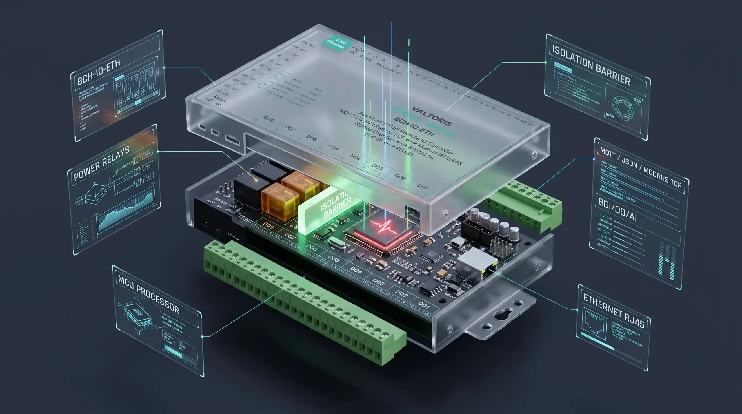
Architecture Reference: For a practical example of how these physical isolation requirements are engineered alongside native P2P, Modbus, and MQTT capabilities, see the Valtoris Remote I/O hardware architecture below.
Final Thoughts: Engineering Your Network for Scale
Digitizing your dry contacts is no longer just a “smart factory” buzzword. It’s an engineering requirement to fight against the increasing costs of copper cabling and electrical labor. By moving the physical signal conversion to the edge, you immediately have the capability to send key machine statuses to any PLC, SCADA, or cloud dashboard anywhere in the world.
However, modernizing your architecture is a process. Before you purchase any hardware or cut any wires, we recommend following this 3-step integration roadmap:
- Step 1: Audit Your IT Infrastructure. Do you have reliable Ethernet drops, stable Wi-Fi coverage, or strong 4G LTE reception near your remote sensors? The most advanced industrial I/O module is useless without a stable network uplink. Fix the network blind spots first.
- Step 2: Start with a Low-Risk Pilot. Do not digitize your main production line on day one. Start by bridging a non-critical utility alarm (like a basement water leak sensor or a perimeter door contact) to your SCADA system. Use this pilot to observe network latency and prove the ROI to your management team.
- Step 3: Standardize on Universal Hardware. As your facility grows, you will inevitably encounter a messy mix of NPN, PNP, and dry contact sensors. Standardize your edge nodes early. Choose modules with built-in wetting voltage, optical isolation, and hardware debounce so you don’t have to redesign your control cabinet every time a new sensor is added.
By treating your basic I/O signals as digital data rather than electrical burdens, you completely eliminate the physical limitations of your factory floor, future-proofing your facility for whatever integration challenges come next.
Scale Your Connectivity, Not Your Cabling
The Valtoris Remote I/O Series natively supports passive dry contacts with internal wetting voltage. With built-in Modbus TCP, MQTT, logic inversion, and fail-safe watchdogs, it handles the physical layer complexities so your network doesn’t have to.
Frequently Asked Questions (FAQ)
How do I power the Ethernet I/O module if the remote location lacks 110V/220V AC mains?
Most industrial remote I/O module are designed to work with wide range of DC voltage. For example, The Valtoris series is powered by 9~24V DC via a standard plug or terminal block. It is very power efficient with a maximum load of only 300mA@12V with all relays and inputs powered. This makes it easy to power from small DIN-rail power supplies, existing 12v/24V battery banks or solar setups at remote pump stations.
Should I wire my critical alarm as Normally Open (NO) or Normally Closed (NC)?
For telemetry and alarm monitoring, always wire your physical dry contacts as Normally Closed (NC). If the sensor cable is accidentally cut or damaged by equipment, an NC circuit will break and trigger the alarm. If wired as Normally Open (NO), a severed cable would prevent the alarm from ever triggering, resulting in a silent failure.
What is the maximum allowable distance between the dry contact switch and the Ethernet I/O module?
The unshielded physical copper wire between your dry contact and the I/O module should be kept short (ideally under 15-30 meters) to avoid voltage drop and EMI noise. Once the I/O module digitizes the signal, the Ethernet packet can travel 100 meters over Cat6, or infinitely across fiber optics, 4G LTE, and VPNs.
Can I use a Wi-Fi I/O module instead of a hardwired Ethernet or Cellular module?
While Wi-Fi modules exist, they are generally not recommended for mission-critical industrial applications. Heavy machinery, Variable Frequency Drives (VFDs), and dense metal structures cause severe RF interference on 2.4GHz/5GHz bands. For reliable telemetry without pulling copper, hardwired Ethernet or industrial Cellular (4G LTE) gateways with high-gain antennas are the industry standard.
