
RS485 is the backbone of industrial automation, but when communication drops, rs485 troubleshooting can be a nightmare. While it often runs for years without trouble, random timeouts, node dropouts, or corrupted data frames can bring a production line to an expensive halt.
When an RS485 network fails, it’s usually due to one of a few common problems: the cable run is too long, there are too many nodes loading the bus, ground loops are introducing noise, or there are fundamental wiring mistakes.
This guide focuses strictly on hardware repeater diagnostics and isolation fixes. Before replacing hardware, ensure your baseline physical wiring (A/B polarity, grounding, and termination) is fundamentally correct. If you are unsure, please review our Ultimate Guide to RS485 Wiring and Topology first.
Interactive Diagnostic: What is your RS485 network doing right now?
Click your primary symptom below for an instant engineering diagnosis.
Troubleshooting Field Guide
- 1. Do I actually need a repeater?
- 2. Repeater vs. Hub differences
- 3. Terminal meanings (A/B, A1/B1)
- 4. Does wire color polarity matter?
- 5. Termination resistor placement
- 6. Reading diagnostic LEDs
- 7. Step-by-Step No-Comms Checklist
- 8. Do I need an isolated repeater?
- 9. Dealing with short circuits
- 10. Maximum cascading limits
- Symptom-Based Quick Reference
- Hardware Upgrades: Hub & Repeater Selection Guide
1. How do I know if I actually need a repeater?
Three situations call for a repeater:
Distance constraints based on Baud Rate
RS485 is rated for 1200 meters, but only at lower speeds like 9600 bps (per the TIA/EIA-485 standard). Beyond that, the signal degrades and a repeater is needed to boost the voltage differential.
More than 32 devices on a single segment:
Each RS485 transceiver is an electrical load of the bus. Standard RS485 segments are limited to 32 devices. A simple repeater adds one more segment, but remains a linear daisy-chain. For high density networks with up to 256 nodes we recommend using a Multi-port RS485 Hub to split the bus into independent manageable sections. This prevents one bad node from killing the entire communication for your facility.
Ground potential differences
When RS485 nodes are distributed across different buildings or large facilities, their local earth grounds are rarely at the exact same voltage potential. This difference drives a “ground loop” current through the RS485 cable shielding or ground wire, severely corrupting data and potentially frying transceiver chips. An isolated repeater effectively breaks this electrical path, providing galvanic isolation while allowing the data signal to pass through safely.
2. What’s the difference between a repeater and a hub?
People use these terms interchangeably, but they do different things.
| Repeater | Hub | |
|---|---|---|
| What it does | Boosts signal to extend distance | Splits one signal to multiple devices |
| Ports | Typically 2 ports (in and out) | Multiple ports (4, 8, etc.) |
| Use when | You need to go longer distances | You need to connect multiple devices to one master |
Some devices can do both things. A 4-port hub usually has a repeater function built into it. It splits the signal from the devices and boosts the signal at the same time.
3. What do all these terminals mean? (A/B, A1/A2, B1/B2)
This is where most wiring mistakes happen. Before looking for a complex rs485 wiring diagram, start by verifying the basic terminal layout. RS485 fundamentally uses two wires: A and B. That’s it.
On a repeater or hub, you’ll see terminals like:
- A, B – Usually the master side (input)
- A1, B1 / A2, B2 – Slave ports (outputs)
- GND – Signal ground (optional, but recommended)
- Power – 24V DC input
The rule: A to A, B to B. Always. If you swap A and B on one segment, you’ll get no communication.
4. The “A/B Naming” Industry Trap: Does A always go to A?
In a perfect world, you would just connect A to A and B to B. However, here is the most frustrating secret in industrial networking: Manufacturers do not agree on what A and B mean.
The original EIA-485 standard defines ‘A’ as the inverting signal (-) and ‘B’ as the non-inverting signal (+). But massive chip makers and equipment vendors reversed this, defining A as (+) and B as (-).
The Ultimate Rule: Ignore the letters A and B if dealing with mixed vendors. Look for the polarity symbols. Always connect (+) to (+) and (-) to (-). If a new device refuses to communicate despite perfect baud rates, swapping the two wires is the very first thing you should try. It will not damage the hardware.
Regarding wire colors: The jacket color is irrelevant to the protocol. If your twisted pair uses red and black wires, arbitrarily designate one color for (+) and the other for (-), and document it across the entire daisy-chain.
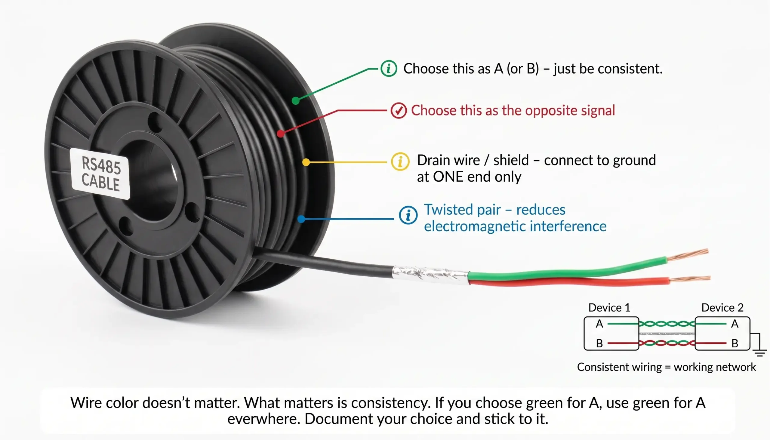
Some cables have a kind of wire inside called a twisted pair. This twisted pair also has a drain wire. The drain wire is used for the ground not for the signal. It is there to help with the shield ground, not the signal that the cable is carrying.
5. Where do I put the termination resistor?
Termination resistors (typically 120Ω) go at the physical ends of the RS485 cable—not at every device, not at the repeater (unless it’s at the extreme physical end of the run).
Watch out for long stubs: Running a long cable from the repeater to a device creates a stub (branch). Keep stubs strictly under 3 meters. Long stubs act as antennas, causing severe signal reflections that termination resistors cannot fix.
If your repeater is in the middle of the line, do not terminate it. Only terminate the ports that are at the cable ends. Some repeaters have built‑in termination switches. Turn them on only for ports that are at the line ends.
5.5 What about Idle Bus Errors? (Failsafe Biasing)
If your bus works perfectly while data is transmitting, but you receive garbage characters (random noise) when the line is idle, you are missing failsafe bias resistors (Pull-up & Pull-down).
When no device is talking, the RS485 line floats into a high-impedance state. Environmental EMI (like a nearby motor starting) can cause tiny voltage spikes that the transceivers misinterpret as a “Start Bit”. Industrial active hubs and repeaters have built-in bias resistors that lock the A and B lines to a stable, known voltage when the bus is idle, preventing ghost data.
6. What should the LEDs tell me?
Most repeaters have status LEDs. They’re your first troubleshooting tool.
| LED | What It Means | Normal State |
|---|---|---|
| Power | Device has power | Solid on |
| TX/RX | Data transmitting/receiving | Blinks with traffic |
| Port LEDs | Activity on specific ports | Blinks with traffic |
| Error | Something wrong | Should be off |
If a port LED never blinks, check wiring on that segment. If the error LED is on, check for short circuits or address conflicts.
7. I added a repeater and still have no communication. Now what?
Go through this checklist in order:
1. Check power requirements: Is the repeater’s power LED on? Be certain you are using a good quality regulated 9-24V DC supply. Never use undersized 5V USB adapters. Never daisy chain power through the data cable to multiple repeaters. This creates severe voltage drops. Give each repeater a local power supply.
2. Check A/B wiring: Are A to A and B to B all the way? Swap A and B on one segment as a test.
3. Check termination: Do you have two (and only two) terminators at the far ends?
4. Verify Cable Type (Twisted Pair): Are you using true shielded Twisted Pair (STP) cable? Standard parallel power cables (like RVV) offer zero noise immunity and will easily corrupt data.
5. Verify Software Parameters: Hardware is only part of the game. Ensure the Baud Rate, Data Bits, Parity, Stop Bits and Slave IDs are identical on 100% of nodes. One mismatch means no communication.
6. Check Failsafe Biasing: If you see garbage data or random errors when the bus is idle you do not have pull up / pull down bias resistors to keep the bus at a known stable state.
7. Check one segment at a time: Disconnect one side. Can devices on side A talk to each other? If not, problem is inside that segment.
8. Check for shorts: Measure resistance between A and B. Should be 120Ω if terminated, or open/infinite if not. If it’s near 0, you have a short.
9. Test with just two devices: Remove everything except the master and one slave. Add them back one by one until the problem reappears.
8. Do I need an isolated repeater?
Isolation protects against ground loops and voltage spikes.
A critical installation error is grounding the cable shield at both ends. Doing so acts as an antenna and forces current to flow through the shield, which is the leading cause of a destructive rs485 ground loop. Always ground the shield at one end only (preferably at the master PLC). If ground potentials between buildings or machines are drastically different, an isolated repeater is strictly required.
You need isolation if:
- Devices are in different buildings (different ground potentials)
- You’ve had unexplained data errors or equipment damage
- The cable runs outdoors (lightning risk)
- There are motors, VFDs, or other noise sources nearby
You can skip isolation if:
- All devices are in the same panel
- Grounding is solid and tested
- No history of noise problems
Isolated repeaters cost more. They’re worth it when you need them.
9. If one segment shorts, will it take down the whole network?
With a standard repeater: yes. A short on one side can drag down the other side.
With an isolated repeater: no. Isolation keeps the two sides electrically separate. A short on side A won’t affect side B. This is a major advantage of isolation—it contains faults to one segment.
10. How many repeaters can I chain together?
In theory, you can chain multiple repeaters to extend a network indefinitely. A repeater physically regenerates the voltage differential of the RS485 signal, pushing it another 1200 meters.
In real-world industrial applications, however, the practical limit is dictated by propagation delay and timing jitter:
- Propagation Delay: Every repeater introduces a microsecond-level hardware delay to process and regenerate the bit. If you cascade 4 or 5 repeaters, the cumulative delay might exceed your master PLC’s strict Modbus response timeout threshold, causing silent communication failures.
- Signal Jitter: Cascading too many network repeaters rs-485 degrades the signal’s timing integrity (jitter).
The Golden Rule: Most robust field applications rarely cascade more than 3 repeaters in a single linear run. If you need to cover massive distances with dozens of nodes, you should transition to Fiber Optic Modems or use a Multi-port RS485 Hub to branch the network efficiently.
Quick Reference: Symptom-Based Troubleshooting
- Random timeouts when large motors start: Classic EMI or Ground Loop. Ensure that the cable shield is grounded at only one end. If problem persists, install an Isolated RS485 Repeater to isolate the ground loop current.
- Nodes after the repeater are dead: Check polarity (Data A/B reversed on output), or verify you didn’t incorrectly place a 120Ω resistor on the repeater’s middle terminals instead of the physical end of the wire.
- High latency, slow SCADA updates: You may have too many repeaters cascading on one line. Reduce hop count by splitting your linear wiring into independent branches using an Active RS485 Hub.
Hardware Upgrades: Specifying the Right RS485 Hub
If your troubleshooting confirms that your network is suffering from ground loops, severe EMI, or bus overloading due to connecting RS485 more than 32 devices, rewiring won’t fix it. You need hardware intervention to isolate the faults and expand your RS485 maximum nodes.
A Critical Warning on “Cheap” Splitters: Avoid passive RS485 splitters. A passive splitter simply ties wires together inside a plastic box, which actually creates signal reflections and guarantees a star topology failure. Industrial applications require an Active RS485 Hub, which physically regenerates the signal and provides independent optical isolation for every single branch.
Scenario-Based Hardware Selection
Replacing a burned-out repeater with the wrong topology hardware will immediately recreate the fault. Match your physical layout to the correct gateway:
Scenario 1: Star Wiring & Branches
The Need: Wiring sensors in a “hub-and-spoke” layout, causing severe signal reflections.
The Fix: A 4-Port Isolated RS485 Hub. Physically splits the main bus into 4 reflection-free, isolated branches.
Scenario 2: Massive Node Density
The Need: Connecting 60+ devices in a noisy environment without crashing the bus.
The Fix: An 8-Port Isolated Hub. Segregates the electrical load, safely expanding the RS485 maximum nodes limit.
Scenario 3: Dual-Master Redundancy
The Need: Two separate PLCs/HMIs need to poll the exact same RS485 sensors simultaneously.
The Fix: An Active Caching Hub. Buffers Modbus queries to prevent data collisions.
Scenario 4: Distance Extension Only
The Need: Pushing a single linear daisy-chain beyond the 1200-meter limit.
The Fix: A standard 2-port repeater with 2500V isolation. Simply bridges Port A to Port B.
RS485 Network Still Crashing? Let’s Fix It.
Replacing standard repeaters won’t fix ground loops or star topology reflections. Please describe your network layout (node count, distance, and symptoms) in the comments below. Our industrial networking engineers will diagnose the root cause and spec the exact isolated hub needed to stabilize your SCADA system.
