

In industrial automation, few things are as notoriously difficult to troubleshoot as an unstable RS485 network. When a Modbus RTU system works perfectly on a schematic but drops packets, experiences “ghost timeouts,” or completely collapses on the factory floor, the root cause rarely lies in the software—it is almost always a physical layer breakdown.
When expanding these networks, splitting a bus or battling electrical noise, engineers are faced with a choice: use a cheap, passive RS485 splitter (essentially a terminal block tying wires together) or invest in an active, Industrial RS485 Hub. Sometimes a passive splitter will work in a clean lab environment. But in a factory floor with Variable Frequency Drives (VFDs), shifting ground potentials, and complex physical layouts, passive splitters are a guaranteed recipe for unstable SCADA data.
Quick Diagnostic: Code Issue vs. Physical Layer Failure?
Before spending hours rewriting your PLC polling logic, check your physical topology. If you answer “Yes” to any of the following, you have a hardware-level issue:
Breaking the “Daisy-Chain” Rule: How to Safely Build an RS485 Star Topology
If you hang around industrial forums like PLCTalk or Reddit’s automation threads, you’ll find a huge, ongoing debate about RS485 topologies. The TIA/EIA-485 standard is very specific about how RS485 networks must be wired: as a continuous “daisy-chain” line with 120Ω termination resistors used only at the two physical ends of the trunk.
However, facility layouts rarely respect textbook standards.
Electricians and integrators are frequently forced to wire RS485 in a “star” or “tree” topology—running multiple branches back to a central control panel—because retrofitting a true daisy-chain through an existing building is physically or financially impossible.
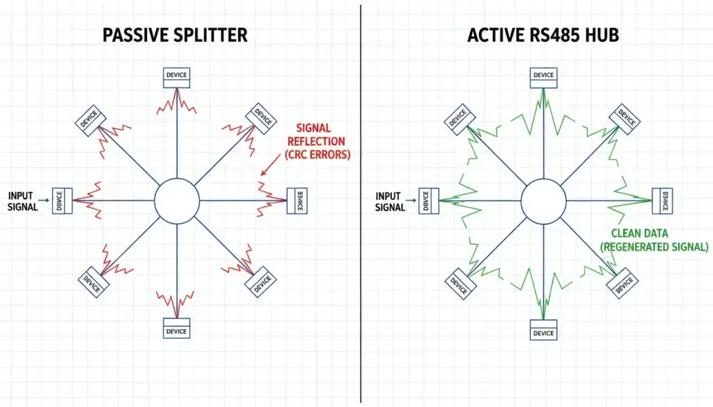
When you use a passive splitter to create a star topology, you are creating long, unterminated “stubs” (drop lines).
The Physics of Failure: Signal Reflection
When high-speed digital pulses travel down a copper wire and hit the end of an unterminated stub, the electrical energy doesn’t just disappear. Because of impedance mismatching, the energy bounces back along the wire. This is known as signal reflection or a standing wave.
According to transmission line principles documented in the Texas Instruments RS-485 Design Guide, when these reflected waves collide with the incoming data stream, they distort the square waves. A clean 1 or 0 becomes a distorted voltage spike. The receiving PLC cannot read the bit, resulting in a CRC error and a Modbus timeout.
The Active Hub Solution
An industrial RS485 hub is not a splitter; it is a topology translator.
Instead of passively splicing copper wires together, an active hub contains individual transceivers for every single port. When a signal arrives from the master PLC, the hub’s microprocessor reads the digital data, processes it, and re-transmits a completely fresh, mathematically perfect square wave down every isolated branch.
Because the hub actively handles the transmission, each port acts as the beginning of a brand-new RS485 segment. This completely eliminates the stub length issue and signal reflection, allowing you to safely build out massive star topologies without violating the underlying physics of the RS-485 standard.
Preventing Network Collapse: Port-Level Isolation for Modbus Faults
A further significant frustration of traditional daisy-chained RS485 networks or networks using passive splitters is their single point of failure vulnerability.
In typical serial setups, all devices use the same physical copper lines (D+ and D-). As one Reddit automation engineer aptly put it, compared to modern Ethernet networks: “If an IP device dies, it doesn’t take the whole bus down with it. “There are some RS485 busses which have exactly that problem.”
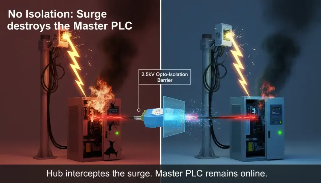
If one VFD in a daisy chain suffers a short circuit, or if a lightning strike induces a massive voltage spike on a single outdoor sensor, that destructive voltage travels down the shared copper lines and hits the transceivers of every other device on the network. A single $50 sensor failing can instantly fry a $3,000 Master PLC.
The Threat of Common-Mode Voltage
Even without a catastrophic lightning strike, “ground loops” are a silent killer. In large facilities, ground potential is rarely the same across different buildings or panels. If Panel A is grounded at 0V, but Panel B (300 meters away) is grounded at 5V due to heavy machinery leakage, a current will flow through the RS485 shield or reference ground. This is called Common-Mode Voltage (CMV). If the CMV exceeds the standard RS485 transceiver limits (-7V to +12V), communication halts entirely.
How Port-Level Isolation Saves the Network
Industrial RS485 hubs feature Galvanic Isolation on every single port. Instead of copper traces connecting Port 1 to Port 2, the data is passed internally using optocouplers (LEDs and phototransistors). The signal is transferred as light, completely severing the electrical connection.
If a massive surge hits the branch connected to Port 3, or a severe ground loop develops, the optocoupler absorbs the hit. Port 3 might lose communication, but Ports 1, 2, and 4—and most importantly, the Master PLC—remain completely isolated, safe, and online. You compartmentalize the failure, saving both hardware and thousands of dollars in facility downtime.
Pushing the Limits: Expanding RS485 Distance and Node Capacity with Active Repeaters
Engineers frequently hit the physical limits of the RS485 standard. Discussions across integration forums confirm that unexplained data corruption often occurs when trying to push past two specific boundaries: node capacity and cable length.
1. The Node Capacity Limit (Unit Loads)
The original EIA-485 specification specified a standard receiver input impedance of 1 “Unit Load” (UL) and stated that a bus could accommodate a maximum of 32 ULs. Modern transceivers use fractional unit loads (e.g., 1/8 UL, allowing up to 256 devices). Older legacy devices, VFDs, and cheap sensors still draw a full unit load. If you put 40 standard devices on a passive splitter network, the transceivers just don’t have the pushing current to drive the voltage high enough to read.
2. The Distance Limit and Cable Capacitance
The theoretical limit of RS485 is 1,200 meters (approx. 4,000 feet). However, as a cable gets longer, it acts like a capacitor. It absorbs the sharp, vertical edges of the digital square waves, rounding them off. By the time a signal travels 800 meters, a sharp 1 might look like a sluggish, curved bump, causing the receiving device to misread the timing.
Active Repeater Capabilities
An industrial hub doubles as an Active Repeater. Because it utilizes an onboard microprocessor to read and rebuild the signal, it acts as a fresh starting point.
If you place a hub at the 1,000-meter mark, you reset the clock. The hub reads the degraded signal, reconstructs a perfect square wave, and blasts it out for another 1,200 meters. Similarly, because the hub’s port is driving the line, it resets the Unit Load count, allowing you to add another 32 (or more) devices to that specific branch.
| Physical Limitation | Passive Splitter Network | Active RS485 Hub Network |
| Maximum Distance | Degrades rapidly; drops past 1200m total. | Resets distance limit (1200m per branch). |
| Node Capacity | Limited by Master’s drive strength (typically 32 nodes). | Resets capacity limit (32+ nodes per port). |
| Signal Waveform | Rounds off over distance (capacitive loading). | Regenerated to sharp, factory-spec square waves. |
| Baud Rate Support | Lower baud rates required for long distances. | Supports high baud rates (e.g., 115200 bps) over longer composite networks. |
Surviving VFD Noise: Why Opto-Isolation is Critical for Industrial Environments
Industrial environments are brutally noisy from an electromagnetic perspective. Engineers constantly battle Electromagnetic Interference (EMI), with Variable Frequency Drives (VFDs) being the primary culprits.
As one forum user reported during a SCADA commissioning: “The fan drivers made so much EMF that after turning more than 4-5 on the network I would have tonnes of packet loss, a couple more and I’d lose all comms.”
Interactive Demo: Opto-Isolation vs. VFD Surge
Click the button below to simulate a high-voltage transient from a Variable Frequency Drive.
Why VFDs Destroy RS485 Data
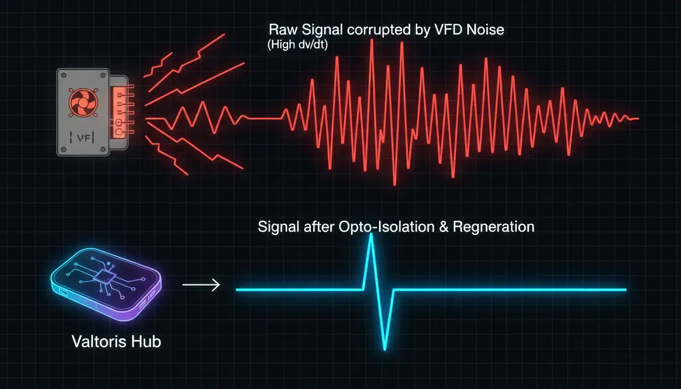
VFDs control motor speed using Pulse Width Modulation (PWM). They rapidly switch high voltages on and off using Insulated-Gate Bipolar Transistors (IGBTs). According to IEEE guidelines on industrial EMI mitigation, this incredibly fast switching creates high-frequency voltage transients (high dv/dt).
These high-frequency transients radiate outward and couple—both capacitively and inductively—into nearby RS485 communication lines. This induces “noise spikes” directly onto the serial data. Because passive splitters have no filtering or isolation, this noise travels freely across the entire network, overwhelming the differential receivers of the PLCs.
The Critical Role of Opto-Isolation
This is where standard commercial equipment fails and industrial-grade hardware becomes mandatory.
An active industrial hub features built-in opto-isolation (often rated for 2.5kV to 3kV). As mentioned earlier, opto-isolators convert the electrical data signal into light, send it across a microscopic physical gap, and convert it back to electricity.
Electrical noise, EMI transients, and VFD harmonics cannot cross a physical gap. The light pulses pass through flawlessly, while the destructive electromagnetic noise is trapped on the isolated side and drained to the earth ground. By placing an isolated hub between your VFD network segment and your main PLC network, you create an impenetrable firewall against electrical noise.
Don’t Compromise the Physical Layer
When your Modbus polling software is throwing timeout errors, it is rarely a software issue. It is almost always a physical layer breakdown.
Standard, passive splitters are perfectly fine for clean, short-distance lab setups. However, when you step onto a high-EMI factory floor, attempt to route cables in a star topology, or push the limits of distance and capacity, a passive splitter becomes a liability.
Deploying an Active, Opto-Isolated RS485 Hub is not just an upgrade, it is an engineering requirement for data integrity. An active hub regenerates the physical signal, isolates electrical faults and blocks VFD noise to keep your control systems responsive, safe and online.
Ready to Permanently Fix Modbus Timeouts and VFD Noise?
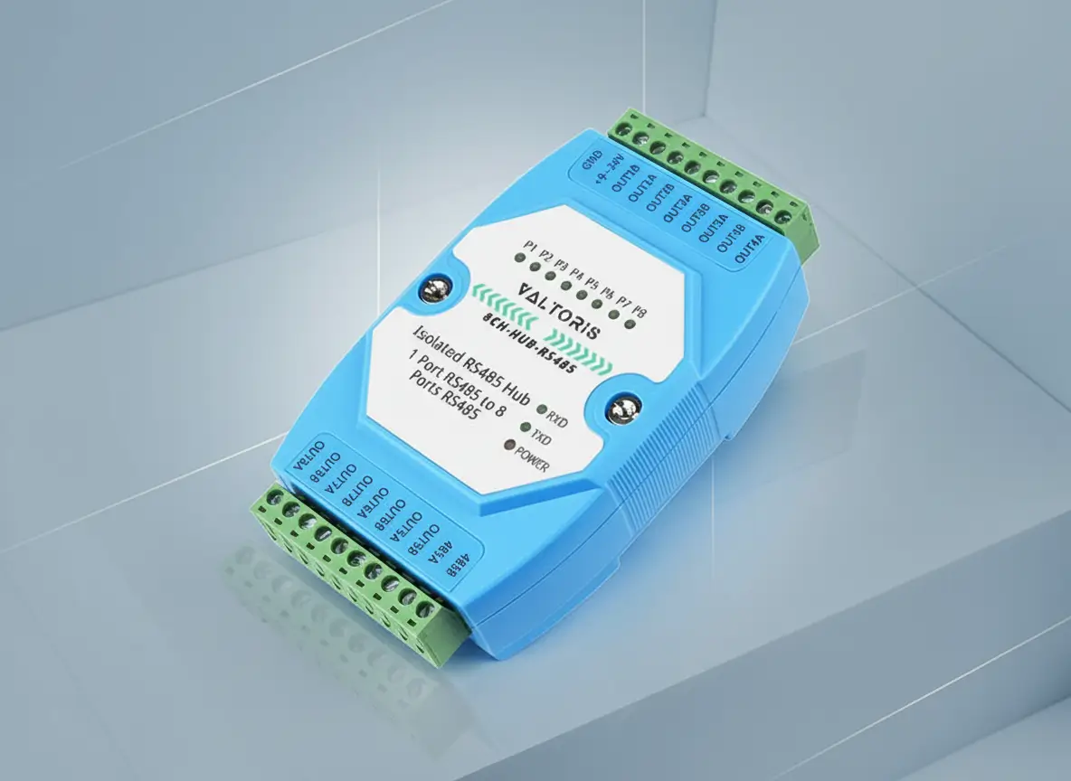
Stop wasting hours troubleshooting ghost errors caused by star topologies and ground loops. Deploy a Valtoris Active RS485 Hub to isolate faults and protect your Master PLC.
Frequently Asked Questions (FAQ)
Q1: If I use an active hub to create a star topology, where do I put the 120-ohm termination resistors?
A: This is a common point of confusion. Because an active hub isolates each port, every branch effectively becomes its own independent RS485 network. You should place a 120-ohm termination resistor at the far physical end of each branch (at the last sensor or drive). Do not place resistors at the hub’s output ports, as the hub’s transceivers already manage the origin point of the signal.
Q2: Does an active RS485 hub add latency to my Modbus RTU polling?
A: Standard active repeaters and isolated hubs add a microscopic propagation delay (typically measured in nanoseconds). For 99% of Modbus RTU SCADA systems, this delay is entirely negligible and will not cause polling timeouts. In fact, by eliminating signal reflections and CRC errors, a hub dramatically speeds up your network by reducing the need for packet retransmissions.
Q3: Can an RS485 hub connect legacy devices running at 9600 bps to a new PLC running at 115200 bps?
A: A standard RS485 repeater hub requires all devices on all branches to share the exact same baud rate and parity. However, if you are dealing with mismatched serial parameters, you need a Caching Hub. Devices like the [Valtoris 2CH-HUB-RS485 Caching Hub] act as a buffer, allowing you to set independent baud rates (e.g., 115200 for the Master port, 9600 for the Slave port) so older legacy sensors can communicate seamlessly with modern, high-speed controllers.
Q4: My Master PC only has an RS-232 port available. Do I need a separate converter before the hub?
A: Can I add an RS-232 to RS-485 converter in a normal hub? A: No, it adds unnecessary points of failure. The most reliable way is to use a hybrid device such as a [4-Port RS232/485 Isolated Hub]. This allows you to connect your legacy RS-232 Master directly into the hub which then effortlessly converts, isolates and distributes the signal into multiple RS-485 branches.