
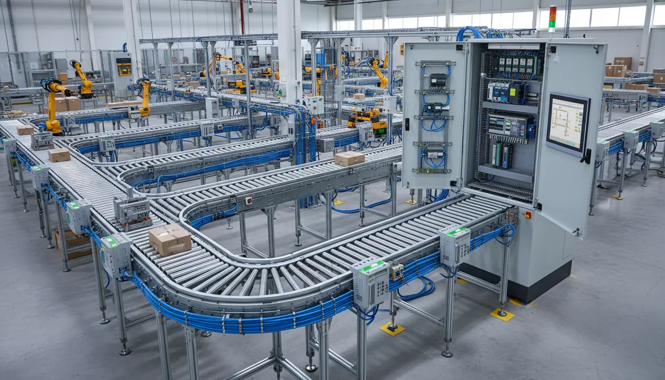
In distributed industrial control systems (DCS), the most critical point of failure rarely lies in the cloud or the central processor; it lies at the physical edge. In industrial forums, it is a well-documented scenario: an integrator attempts to trim the bill of materials by deploying generic, unbranded relay boards, only to suffer catastrophic field failures when a minor voltage transient across the factory floor permanently destroys the main SCADA PLC.
The root cause is almost always a failure to specify hardware engineered for hostile electrical environments. Selecting Modbus RTU I/O modules is not merely a pin-matching exercise. It requires calculating RS485 impedance limits, isolating ground loops, matching ADC resolutions, and managing polling latency.
This definitive engineering guide breaks down the strict technical specifications required to select industrial remote I/O hardware, eradicate persistent communication errors, and deploy zero-code configuration software to guarantee network survival.
Table of Contents
- 1. Mitigating Ground Loops via Galvanic Isolation
- 2. Auditing Field Signals: DI, DO, AI, and Watchdogs
- 3. Interactive I/O Module Specifier (Tool)
- 4. Defeating Modbus Latency: Active Reporting & P2P
- 5. Node Capacity & RS485 Distance Diagnostics
- 6. Decoding Modbus Exception Codes & Registers
- 7. Architectural Scalability: Modbus TCP to MQTT
- 8. Frequently Asked Questions (Troubleshooting)
1. Mitigating Ground Loops via Galvanic Isolation
The primary cause of hardware destruction in large RS485 networks is the ground loop. In things such as water treatment plants or large agricultural facilities, different buildings will always have different earth ground potentials. If you take a commercial IO module (not isolated) and connect it to a central PLC, any voltage difference will try to equalize, and it will do that right across the copper data lines.
That stray current not only scrambles the differential signaling, causing CRC checksum errors, but in a surge it will bypass the transceiver chip and fry the logic boards upstream.
(Safe Zone)
(High Noise / Surge Zone)
When auditing hardware datasheets, compare the protection specifications rigorously. Consumer-grade components will fail under standard factory floor conditions.
| Specification Parameter | True Industrial Grade (e.g., Valtoris) | Commercial / Hobbyist Grade |
|---|---|---|
| Galvanic Isolation | 2500V to 3000V (Optocoupler) | None (Direct electrical connection) |
| Operating Temperature | -40°C to +85°C (Outdoor NEMA ready) | 0°C to 50°C (Climate-controlled only) |
| Power Supply Input | 9V ~ 24V DC Wide Terminal Block | Fixed 5V/12V DC Barrel Jack |
| EMC Protection | Severe surge & ±15kV ESD protection | Minimal to none |
Table 1: Physical layer parameter comparison between industrial and commercial I/O modules.
2. Auditing Field Signals: DI, DO, AI, and Watchdogs
A secondary point of failure is mismatching the I/O module’s electrical architecture to the physical field instruments. This results in either welded contacts or a failure to trigger logic states. You must categorize your panel requirements strictly.
Digital Inputs (DI): Sinking vs. Sourcing Logic
Digital inputs register binary states (ON/OFF) from devices like limit switches and proximity sensors. Modules must natively support both Passive Switches (Dry Contacts)—which require only a bridge to the GND terminal—and Active Levels (Wet Contacts).
For standard 24VDC industrial control panels, a robust module detects an active low between 0~17V and an active high between 17~24V. Ensuring wide voltage thresholds prevents false triggers caused by minor voltage drops over long NPN (Sinking) or PNP (Sourcing) sensor cable runs.
Digital Outputs (DO): Relays vs. Solid-State
Specifying the wrong DO type is catastrophic. Solid State Transistors switch in microseconds but are restricted to very low-power DC loads. If you are driving motor contactors, solenoid valves, or alarm beacons, you require Mechanical Relays.
Industrial standard modules, such as the Valtoris IO series, provide rugged mechanical relays rated for 5A at 250V AC or 5A at 30V DC. This massive load flexibility allows you to mix AC and DC loads on the same remote node safely.
Fail-Safe Operations: The “DO Hold Time” Watchdog
What happens if your master PLC crashes or a forklift runs over the RS485 cable while a relay is telling a chemical pump to run? If the remote I/O module has no watchdog, the relay stays closed forever, which spells disaster.
Require a DO Hold Time (Data Retention) feature when selecting hardware. Valtoris modules enable engineers to configure a precise watchdog timer. If the module does not receive a valid Modbus command within the time frame (5 seconds), the module will drop all relays to a safe disconnected state on its own.
Analog Inputs (AI): ADC Resolution
Analog inputs acquire continuous variables—such as pressure from a 4-20mA transmitter or flow rates from a 0-5V or 0-10V sensor. Industrial modules integrate a 12-bit ADC, dividing the incoming signal into 4,096 distinct steps, providing highly accurate SCADA telemetry.
Beyond raw hardware resolution, high-end modules perform algorithmic noise filtering at the edge For example, Valtoris controllers have a high-precision AI numerical calculation mode that automatically suppresses micro-fluctuations and environmental noise to 0 voltage limits. The module also offers pre-calculated floating-point (Float) data via specific extended registers, thus avoiding the need to force the PLC to calculate raw HEX values and saving hours of SCADA programming.
| Signal Category | Supported Electrical Formats | Fail-Safe / Precision Metric |
|---|---|---|
| Digital Input (DI) | Dry Contact, Wet Contact (17-24VDC High) | Hardware Debouncing Filters |
| Digital Output (DO) | 5A @ 250VAC / 30VDC Mechanical Relay | “DO Hold Time” Watchdog Timer |
| Analog Input (AI) | 0-5V, 0-10V, 4-20mA | 12-bit ADC Resolution |
Table 2: Standard industrial I/O signal matching and fail-safe chart.
3. Interactive I/O Module Specifier
4. Defeating Modbus Latency: Active Reporting & P2P Control
A common misconception for many IT engineers new to the Operational Technology (OT) space is that Modbus RTU is a hard real-time. It doesn’t, essentially.
Modbus RTU is a Master-Slave polling protocol. The Master PLC has to ask Node 1 for it’s status, wait for the response, process it, then ask Node 2. If you have 30 devices daisy chained on a slow 9600 bps bus it might take a few seconds for the PLC to recognize that a critical limit switch was tripped. This intrinsic latency is a complete mismatch to traditional Modbus polling for emergency interlocks or high speed machinery.
The Edge Computing Solution: Active Reporting
Modern RS485 remote IO controllers overcome this limitation by deploying logic at the edge. Instead of passively waiting for a PLC poll, advanced modules feature Active Reporting. When a Digital Input state changes, the module autonomously constructs and fires a Modbus 0x05 command directly to the network without being asked.
For example, if DI-1 goes low (triggers), the module instantly broadcasts: 00 05 00 10 FF 00 8C 2E to the designated IP address or Master node, completely bypassing the polling queue.
Peer-to-Peer (P2P) Cross-Facility Control
Active Reporting unlocks Peer-to-Peer (DI Controls DO) capability. Imagine a float switch in a remote reservoir that needs to shut off a pump located 2 miles away. Instead of routing this logic through a vulnerable central server, you can pair two Valtoris controllers. A triggered Digital Input on the Client Module automatically sends a command over the Ethernet or 4G network to the Server Module, instantly closing the corresponding Digital Output relay. This localized edge-logic removes the central PLC as a single point of failure.
| Communication Method | Mechanism | Latency Impact | Best Application |
|---|---|---|---|
| Traditional Polling | PLC asks sequentially | High (Depends on node count) | General SCADA monitoring, temp logging |
| Active Reporting (P2P) | Module pushes data instantly | Ultra-Low (Milliseconds) | Emergency shutoffs, remote pump control |
Table 3: Comparison of Modbus polling latency vs Edge Active Reporting.
5. Node Capacity & RS485 Distance Diagnostics
If your architecture uses an RS485 physical layer, 90% of all “Timeout” or “CRC Checksum Error” diagnostics are caused by bad wiring. To create a stable bus you must adhere to the strict electrical rules as found in the authoritative RS-485 Design Guide by Texas Instruments.
- Daisy Chain Topology Only: RS485 should be wired in daisy chain. “Stars” or “T-Junctions” create unterminated stubs which cause signals to reflect back and collide with new data destroying the square waves.
- 120Ω Termination Resistors: The very first and last physical device on the trunk must have a 120Ω resistor across the D+ (A) and D- (B) terminals to absorb the signal and prevent echo.
Node Capacity & 1/8 Unit Load Transceivers
Bus capacity is a frequent source of confusion in hardware selection. The original EIA-485 standard specifies a maximum of 32 “Unit Loads” (devices) per bus segment. But modern, high grade transceivers have an input impedance of 1/8 Unit Load. Mathematically this allows up to 256 devices on one physical bus without the need of an active repeater. When you specify hardware, always check the transceiver unit load rating if you want to go beyond 32 nodes.
| Baud Rate | Maximum Copper Distance (Approx.) |
|---|---|
| 9600 bps | 1200 m (Optimal for long legacy runs) |
| 19200 bps | 1000 m |
| 38400 bps | 800 m |
| 115200 bps | 400 m (Requires pristine STP wiring & strict termination) |
Table 4: RS485 physical layer distance limits based on baud rate.
6. Decoding Modbus Exception Codes & Registers
Once the physical layer is secure, software configuration presents the next major hurdle. Modbus utilizes specific hexadecimal function codes to read and write memory registers.
Function Code Mapping & HEX Breakdown
Standard implementation relies on codes 01/02 for reading Digital Inputs, 05/15 for forcing Digital Outputs, and 04 for reading Analog Input registers.
To manually command Relay Output 1 (DO1) to close using the 0x05 function code via RTU, a Master PLC must construct and send the following raw HEX frame: 01 05 00 10 FF 00 8D FF.
01: Slave Device Address05: Function Code (Force Single Coil)00 10: Register Address for DO1 (Hex 10 = Decimal 16)FF 00: Data Value (FF 00 means ON, 00 00 means OFF)8D FF: CRC Checksum (Low/High)
Troubleshooting Modbus Exception Codes
If the Master PLC receives an error response, the module is returning an Exception Code. Understanding these codes is critical for field debugging.
| Exception Code (HEX) | Name | Troubleshooting Action |
|---|---|---|
| 01 | Illegal Function | The module does not support the requested function code (e.g., trying to write to an AI register). |
| 02 | Illegal Data Address | The Master requested a register address that does not exist in the module’s memory map. Check your offsets (base 0 vs base 1). |
| 03 | Illegal Data Value | The structure of the data payload is incorrect (e.g., requesting 100 coils when only 8 exist). |
| Timeout (No Response) | N/A | Physical layer failure. Check A/B wire polarity, baud rate mismatch, or missing termination resistors. |
Table 5: Common Modbus Exception Codes and corresponding field actions.
The Zero-Code Solution: VirCom Software
Manually computing CRC checksums and tracking HEX addresses is prone to human error. Hardware selection must include software evaluation. Valtoris mitigates configuration friction by providing the VirCom Virtual Serial & Device Management Tool.
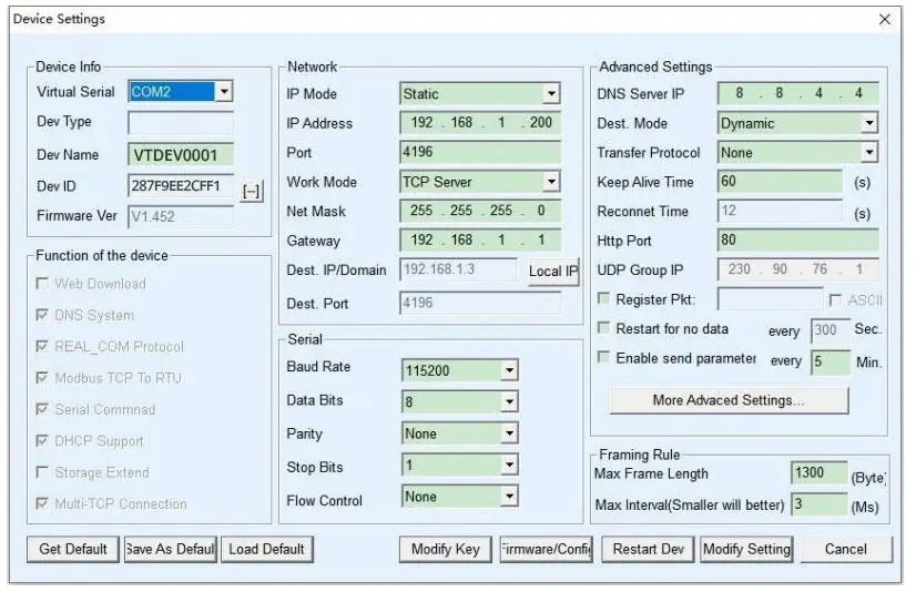
Instead of setting baud rates by flipping tiny DIP switches inside a dark control cabinet, you connect the module via USB or Ethernet. VirCom provides a “One-Click Auto Search” to immediately find the module and then allows you to configure IPs, Baud Rates, Parity, AI calibration and Active Reporting intervals through a clean Windows GUI. It turns hours of manual register mapping into a 5 minute software install.
7. Architectural Scalability: Translating RTU to TCP and MQTT
Modbus RTU over RS485 is unmatched for “last mile” reliability on noisy factory floors. However, the new SCADA and IoT platforms are being deployed over high-bandwidth IP networks. How do you close that gap?
That’s where standard relay boards end and intelligent controllers begin. Some modules have built-in protocol gateways, such as Valtoris 8CH-IO-ETH (Ethernet) and 8CH-IO-LTE (4G Cellular).
They can poll external legacy RS485 sensors on their sub-bus, as well as gather their own DI/DO/AI signals. Then they collect all this data and put it in Modbus TCP packets for local servers on port 502 or format it as JSON payloads. As a full-fledged IoT edge gateway, the 4G LTE models are capable of delivering this JSON data via the MQTT protocol directly to public cloud brokers like AWS, Azure or Alibaba Cloud.
Preventing Data Loss: Offline Storage
Pushing data to the cloud via 4G LTE introduces a new risk: cellular dead zones and tower maintenance. Standard gateways simply drop Modbus packets if the MQTT broker connection fails. Industrial-grade IoT controllers must feature Offline Storage. If the TCP or Cellular link drops, the module buffers the timestamped JSON payloads in its internal memory, autonomously publishing the backlog to the cloud the moment connectivity is restored.
Stabilize Your Control Network Today
Describe your panel requirements and topology below. Our engineering team will analyze your setup and recommend the exact isolated hardware required to permanently eliminate SCADA timeouts.
