
If the physical wiring is proven and communication is functioning but you are getting crazy values on the SCADA screen like 16777215, 65535 or -4.2e-12 then your network is experiencing a data parsing failure. The data corruption is due to the fundamental incompatibility of the modbus data types. The old 16 bit holding registers are not able to read the complex structures of the new industrial sensors .
The root causes of these translation errors usually boil down to three hard categories, modbus endianness mismatch (the dreaded ABCD vs DCBA byte swap), incorrect scaling of signed integers via Two’s Complement, or rs232 to modbus ASCII text string streams not being handled.
This engineering guide provides simple technical solutions for aligning modbus data types between OT and IT systems. Find out how to define the right modbus tcp byte order, avoid the modbus byte swap nightmare and use edge gateways to automate conversions without modifying PLC ladder logic.
Quick Navigation: Find Your Solution
Part 1: Software-Fixable Traps
Part 2: Hardware-Mandated Trap
Interactive Diagnostic: Select Your Symptom
Choose the exact error you are seeing on your SCADA screen to jump to the solution.
The Modbus Data Type Gap: Why Modern Sensors Crash PLCs
90% of data parsing errors have their roots in the protocol’s beginnings. The industrial world was a lot more simple when Modicon brought out the Modbus protocol in 1979. The protocol depended on a very strict minimalist dictionary.
To this day, native Modbus only understands two fundamental data types:
- Coils / Discrete Inputs: 1-bit boolean values (ON/OFF).
- Holding / Input Registers: 16-bit unsigned integers (ranging from 0 to 65,535).
See what is missing? The Modbus protocol dictionary has zero concept of 32-bit float numbers (Float32), double precision (Float64), negative numbers (Signed Integers) or text strings (ASCII). Modern smart sensors, however, are totally dependent on these complicated data formats.
| Data Requirement | Sensor Output Format | Modbus Native Capacity | The Engineering Workaround |
|---|---|---|---|
| Precision Temperature | 32-bit Float (IEEE 754) | 16-bit Integer only | Split across TWO consecutive registers. |
| Negative Pressure (-50 Pa) | Signed Integer (Int16) | Unsigned Integer (Uint16) | Use Two’s Complement hexadecimal math. |
| Laser Distance Reading | ASCII String (” 100″) | No String Support | Strip characters, convert to Hex, split into registers. |
Modbus Endianness: The ABCD vs. DCBA Byte Swap Nightmare
When engineers want to transmit a 32 bit floating point number (say 25.5) via Modbus, they have to split the 32 bits (4 bytes) into two sequential 16 bit (2 byte) registers. That sounds simple until you realize that the Endianness, the order in which those bytes are transmitted and reassembled, was never standardized in the original Modbus specification.
So different manufacturers used different ways of assembly. For example a Siemens PLC may read the bytes in one order but a Schneider Electric VFD might transmit them in another. If the byte order of the sending device is different from that of the receiving device, the data is totally garbled.
| Byte Order Format | Common Naming Convention | How Bytes are Sequenced | Typical Manufacturer Usage |
|---|---|---|---|
| ABCD | Big-Endian / Standard | Byte 1, Byte 2, Byte 3, Byte 4 | Standard Modbus Default |
| DCBA | Little-Endian / Byte Swap | Byte 4, Byte 3, Byte 2, Byte 1 | Intel-based processors, PC SCADA |
| BADC | Byte Swap | Byte 2, Byte 1, Byte 4, Byte 3 | Less common, specific legacy HMIs |
| CDAB | Word Swap / Middle-Endian | Byte 3, Byte 4, Byte 1, Byte 2 | Siemens SIMATIC, Allen-Bradley (some) |
Modbus Float32 Byte Swap Simulator
Enter a decimal number below to see how a protocol mismatch scrambles your hex data across registers.
*If your Master expects ABCD but the Gateway sends DCBA, 100.5 turns into unrecognizable garbage data.
The Memory Level: Why IEEE 754 Floats Fragment
To really get to grips with this protocol mismatch, we need to examine how PLCs allocate physical memory. The IEEE 754 Standard for Floating-Point Arithmetic states that a 32-bit float consists of three parts: a 1-bit sign, an 8-bit exponent, and a 23-bit fraction (mantissa). But Modbus holding registers (the 4X references) are strictly limited to 16-bit blocks.
The gateway or PLC receives these 4 bytes and places them sequentially in memory addresses. If your SCADA system reads Address 40001 expecting the Exponent and receives the Fraction, the mathematical translation blows up. According to system integration whitepapers from the International Society of Automation (ISA), more than 60% of commissioning delays in brownfield plants are directly attributed to undocumented memory mapping differences between multiple IT and OT vendors.
| Memory Block Allocation | IEEE 754 Component | Hex Example (100.5) | Result if Misaligned by 1 Byte |
|---|---|---|---|
| Register 1 (High Word) | Sign + Exponent | 0x42C9 | Massive Exponent (e.g., E+38) |
| Register 2 (Low Word) | Fraction (Mantissa) | 0x0000 | Zero or infinitesimal decimal |
Case Study: Converting RS232 ASCII Strings to Modbus Registers
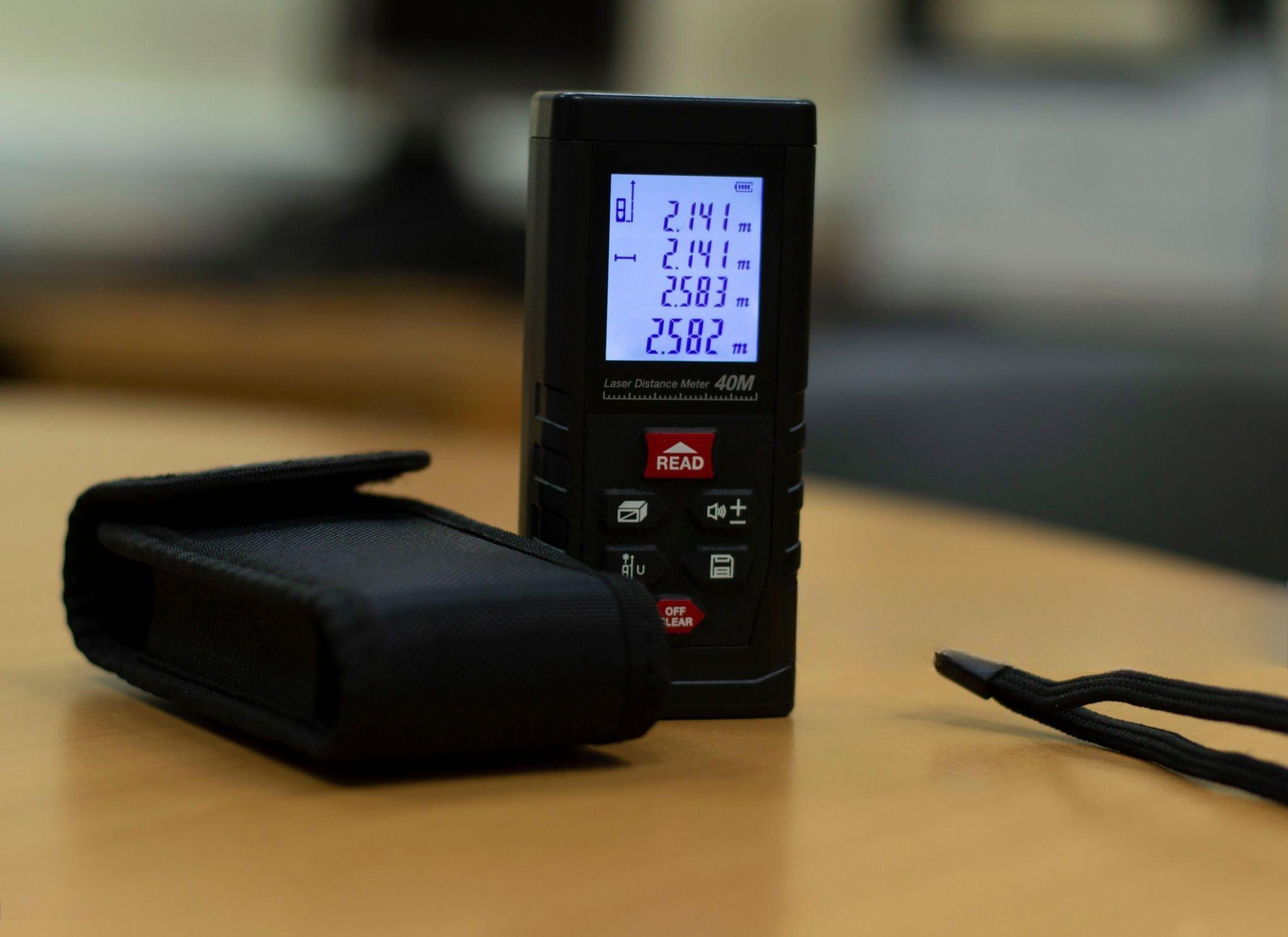
As if dealing with 32-bit floating points wasn’t enough, how about the supreme challenge of bridging a legacy device that spews out raw ASCII text strings to a Modbus network? Let’s consider an example of a Laser Distance Meter in a real-world integration.
The laser meter is on the production line and prints out a string like ” 100\r\n” over an RS232 serial connection. But the centralized touchscreen HMI needs this distance data in Modbus TCP holding registers, specifically mapped to 40001 and 40002 as a 32-bit double word in DCBA byte order. A simple transparent terminal server will fail here as it just passes the ASCII characters through unchanged. The HMI can not parse spaces and text.
Some active conversion is necessary at the gateway edge to successfully bridge this RS232 instrument to the Modbus TCP network, stripping the whitespace, translating the ASCII to a numeric integer, converting it to hexadecimal, splitting it into 16-bit blocks, and finally swapping the bytes to match the HMI’s exact endianness expectation.
| Processing Stage | Data Format | Value / Result |
|---|---|---|
| 1. Raw RS232 Output | ASCII String (Hex) | 20 20 20 20 31 30 30 0D 0A |
| 2. String Parsing & Stripping | Cleaned ASCII | “100” (Whitespaces removed) |
| 3. Integer Conversion | 32-bit Decimal Integer | 100 |
| 4. Hexadecimal Mapping | 32-bit Hex (ABCD format) | 0x00 00 00 64 |
| 5. Apply Target Endianness | Little-Endian (DCBA format) | 0x64 00 00 00 |
| 6. Register Assignment | Modbus 16-bit Registers | Reg 40001: 0x6400 | Reg 40002: 0x0000 |
What if your device isn’t sending a simple "100" but a full 30-character barcode like "1Z9999999999999999999999999999"? Because a single Modbus register holds exactly 16 bits (2 bytes, or 2 standard ASCII characters), a 30-character string must be mapped across 15 continuous Modbus registers.
If your SCADA polling rate is faster than the gateway’s string compilation buffer, the payload will fracture across multiple read cycles, causing random “string length” errors on the HMI. A proper edge gateway allows you to set a Delimiter (like \r\n) or a Frame Timeout to ensure the entire 15-register block is buffered and updated atomically before the master is allowed to read it.
What if the flow meter sends a decimal string like ” 25.43\r\n” or a checksum suffix such as " 100*4A\r\n"? The conversion pipeline becomes exponentially more difficult.
- Floating ASCII: The gateway needs to know about the decimal point, convert the string to a 32 bit IEEE 754 Float and split it correctly in TWO Modbus registers with the right Endianness.
- Checksum Stripping: The firmware of the gateway need to be programd to detect specific delimiters (such as the
*character) and strip out the BCC/Checksum bytes then convert the payload to a number.
Standard transparent protocol converters will completely crash when facing these non-standard string appendages.
Signed vs. Unsigned Integers: Dealing with Negative Numbers
Another common data type failure is when field sensors report negative values, such as a refrigeration monitor reporting -10°C, or a pressure transducer reporting vacuum pressure. Modbus natively communicates Unsigned 16-bit Integers (UINT16) . So it does not know about a minus sign .
Instead , industrial equipment uses a binary method called Two’s Complement to handle negative numbers . If your SCADA polling software ( e.g. , Modscan ) or HMI is not set up to interpret the register as a Signed Integer (INT16) , you get catastrophic misinterpretations .
| Sensor Field Value | Hex Transmitted over Modbus | Read as Unsigned (UINT16) | Read as Signed (INT16) |
|---|---|---|---|
| 0°C | 0x0000 | 0 | 0 |
| +10°C | 0x000A | 10 | 10 |
| -10°C | 0xFFF6 | 65526 (Error) | -10 (Correct) |
If your industrial chiller temperature suddenly spikes to 65,500°C on your SCADA dashboard the moment temperatures drop below freezing, do not panic. Your sensor is not broken; you simply need to change the data type mapping in your HMI from UINT16 to INT16.
The “Off-by-One” Addressing Trap (Zero-Based vs. One-Based)
Sometimes your byte order is just right ( CDAB matches CDAB ) and your data type is correct but you still get absolute garbage in the float value . You have fallen into the Modbus Addressing Offset Trap, 99% of the time.
In Modbus documentation we often see Logical Addresses (e.g. Holding Register 40001). However, in the actual transmission of the Modbus packet over the wire, it uses a Physical Offset starting at zero (0x0000). Depending on the PLC vendor, 0-based addressing could be used versus 1-based addressing and you could end up accidentally reading registers 40002 and 40003 when you really wanted to read 40001 and 40002.
| Intent: Read Register 40001 | Physical Offset Transmitted | Result if Manufacturer uses 1-Based | Result if Manufacturer uses 0-Based |
|---|---|---|---|
| System requests address 1 | 0x0001 | Reads 40002 (Shifted Data!) | Reads 40001 (Correct) |
| System requests address 0 | 0x0000 | Reads 40001 (Correct) | Invalid Request / Error |
Hardware vs. Software: Automating Modbus Data Conversion
When system integrators face mismatched endianness, ASCII string devices, or float32 fragmentation, they generally have two paths to resolve the conflict: the grueling software path, or the automated hardware path.
The Software Approach (PLC Ladder Logic Nightmare)
The translation can be performed by a programr writing custom ladder logic in the master PLC. This includes the use of complex Shift (SHL/SHR) and Rotate instructions to manually swap bytes (moving Byte 4 to the Byte 1 position, etc.), and custom ASCII_TO_HEX blocks to remove whitespace from strings.
Technically, it can be done, but it wastes valuable PLC scan time, requires hours of expensive programming labor, and creates custom “spaghetti code” that is difficult for future maintenance technicians to troubleshoot.
The Professional Edge: Custom Parsing Firmware
Instead of hardcoding complex conversions into the PLC, modern industrial architectures offload this processing to the edge using Custom Parsing Firmware on devices like the 1CH-RS232 Series(V).
The usual “transparent” gateways will fail, because they will pass the \r\n characters and spaces as raw hex, and your SCADA’s Modbus parser will crash. The gateway inverts its usual role by implementing a custom firmware solution. It is a TCP Client that initiates a connection to your SCADA or HMI. The gateway’s internal microprocessor strips out the whitespace from the incoming raw RS232 ASCII string, converts the ASCII to a numeric integer, swaps the byte order to your exact specification (e.g. DCBA) and wraps it into a perfect Modbus TCP Write command.
You do not need to write a single line of PLC ladder logic. You simply provide the sensor’s raw ASCII output format and your SCADA’s required Endianness, and an industrial gateway can be pre-flashed with custom firmware to handle the exact protocol translation autonomously at the hardware edge.
 Figure 6: The Valtoris 1CH-RS232 Series(V). Equipped with custom edge-parsing firmware, it can intercept legacy RS232 ASCII streams, convert them into Modbus TCP integers, and actively write them to your HMI.
SCADA-Specific Quirks: Ignition, Kepware, and FactoryTalk
A common frustration often expressed by integration engineers in the field is why data looks perfect in a raw diagnostic tool such as ModScan32, but fails completely when bound to a tag in modern SCADA platforms.
The difference is only in driver level implementation and syntax syntax. The diagnostic tools just give you the raw hex buffer. SCADA drivers need explicit instructions to build that buffer.
- Inductive Automation (Ignition): Ignition does not have a problem with Modbus addressing on a 1-based index, but drivers can enforce 0-based indexing with a simple checkbox in the OPC UA device configuration. It also handles float swaps at the device level, not at the tag level.
- Kepware (PTC): Kepware has specific suffix notations. You need to add
.F(Float) or@FLOATto your tag address (40001.F). This tells the OPC server to read two registers and internally switch the bytes.
When using a Modbus gateway to pull RS232 ASCII strings (e.g. barcode data), SCADA platforms will expect you to define the String Length in the tag configuration. If your scanner sends “12345\r\n” (7 characters including carriage return and line feed) and your SCADA tag is set to read 5 characters, the buffer will get misaligned on the next read and you will get intermittent dropouts.
Frequently Asked Questions
Q1: Can I fix the DCBA vs. ABCD byte swap issue directly in my SCADA software?
Yes, most modern SCADA platforms like Ignition or Wonderware allow you to change the word/byte order in the device driver settings. However, if you are integrating multiple devices with mixed endianness on the same serial bus, a hardware gateway is the most reliable way to standardize the output before it hits the SCADA.
Q2: Why does my flow meter output data as ASCII instead of standard Modbus RTU?
Many legacy instruments (like weigh scales, barcode scanners, and laser meters) were designed to output raw strings to a local printer or PC terminal via RS232, rather than communicating with an industrial PLC. They lack a native Modbus protocol stack entirely.
Q3: Is there a universal standard for Modbus 32-bit float transmission?
No. Because the original Modicon specification from 1979 only defined 16-bit registers, there is no official standard for 32-bit floats. Manufacturers adopted the IEEE 754 float standard, but the transmission sequence (Big-Endian vs. Little-Endian) varies wildly by brand.
Q4: How do I know if my offset error is caused by 0-based or 1-based addressing?
The easiest test is to read a known, static holding register. If the expected value appears exactly one register address higher or lower (e.g., in 40002 instead of 40001), your master and slave are using different addressing bases. Toggle the “Base 0 / Base 1” setting in your polling software.
Q5: What happens if I try to read an ASCII string device using a standard transparent Modbus gateway?
The transparent gateway will simply dump the raw hex bytes of the ASCII characters (e.g. 0x20 for a space, 0x31 for ‘1’) into your Modbus registers. Your PLC or SCADA will try to interpret these hex values as integers or floats, resulting in completely random, unusable numbers.
Q6: Why does my Modbus device manual say “Swapped Float” but SCADA only gives me Big-Endian or Little-Endian options?
Industry terminology is notoriously fragmented. “Swapped Float” usually refers to Word Swap (CDAB) or Middle-Endian. If your SCADA lacks this specific dropdown, you must use a hardware gateway to pre-process the CDAB byte order into standard Big-Endian (ABCD) before it reaches the SCADA OPC server.
Q7: Can a PLC read 32-bit floats from a Modbus device without a gateway?
Technically yes, but it requires writing complex ladder logic. You must read the two 16-bit INT registers, use Bit Shift (SHL/SHR) or Byte Swap instructions to reorder the data, and then use a COP (Copy) instruction to move the bit pattern into a REAL memory tag. An edge-processing gateway eliminates this PLC overhead completely.
Need to Parse Complex ASCII or Swap Bytes at the Edge?
Standard transparent gateways (like our default 1CH-RS232 Series) excel at standard Modbus TCP to RTU routing, but they cannot natively parse non-standard ASCII strings or restructure floating-point byte orders. Stop wrestling with PLC ladder logic.
The Valtoris Custom Firmware Service:
- Tell us your sensor’s raw ASCII data format (e.g.,
" 25.43kg\r\n"). - Define the required Modbus register map and Endianness for your SCADA.
- We provide a Plug-and-Play Pre-Flashed Edge Gateway that auto-strips, auto-converts & auto-maps your data.
