
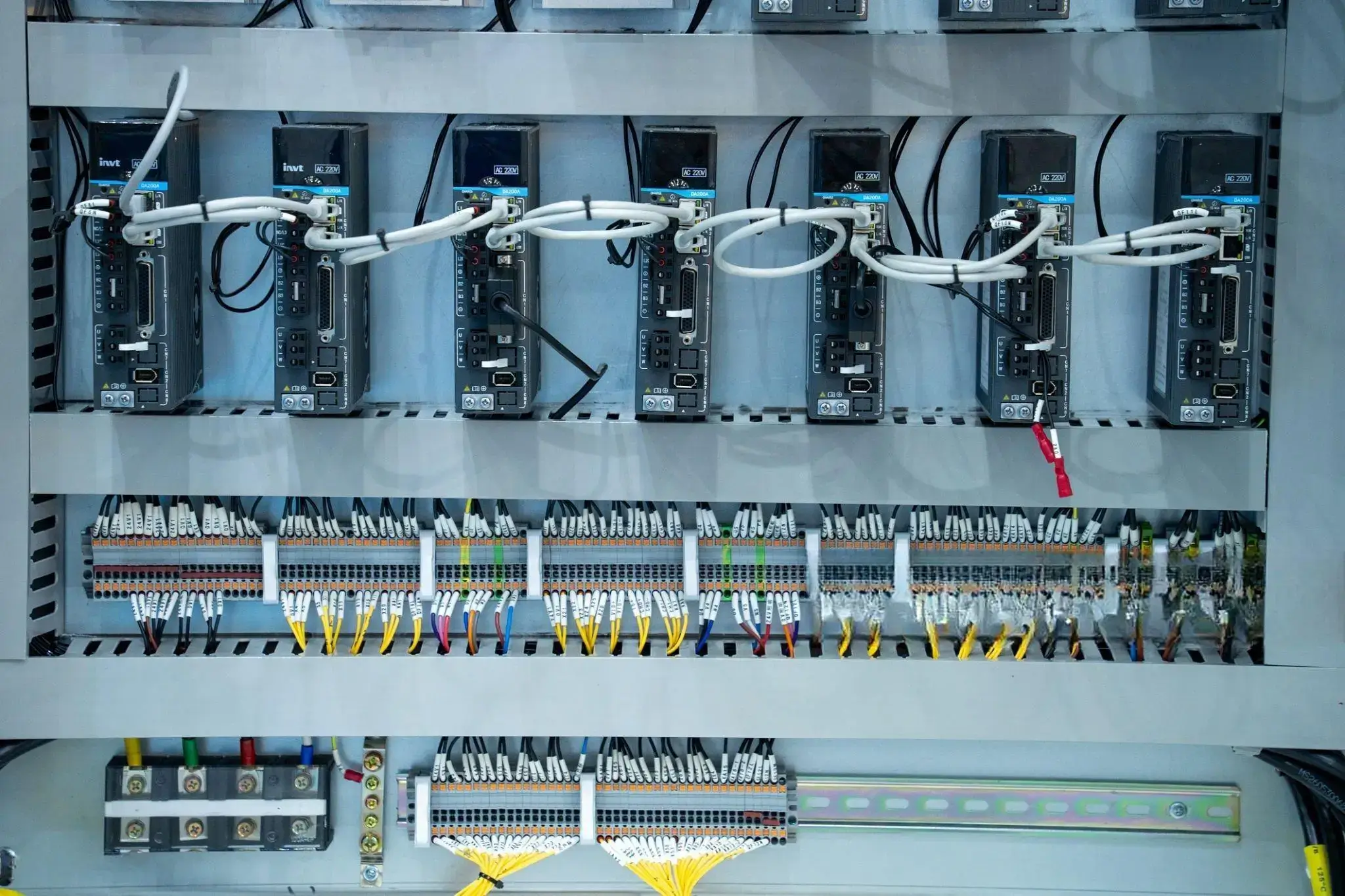
One of the most common reasons for damaged I/O modules and wasted troubleshooting time is wiring a PNP or NPN sensor to the wrong PLC input card. The almost universal confusion comes from mixing “Sinking” and “Sourcing” electrical logic.
This guide skips the heavy solid state physics and gets right to the point. Here are the exact rules of compatibility, foolproof wiring diagrams for 3-wire sensors and a modern field solution for integrating mismatched NPN/PNP sensors into your existing control network without complex relay hacks.
1. The Golden Rule (Read This First Before Wiring)
Before you pick up a screwdriver or strip a wire, you need to verify the fundamental compatibility between your sensor and your controller. The reason so many engineers accidentally damage their PLC cards is that they assume identical polarities should be wired together.
In reality, industrial I/O relies on a completed circuit loop—meaning someone has to supply the voltage, and someone else has to receive it. To guarantee your wiring won’t short out, you must always follow the “Opposites Attract” rule.
Here is the absolute baseline matrix you need to memorize:
| If your Sensor is… | It acts as a… | It MUST connect to a PLC Input that is… |
|---|---|---|
| PNP (Positive-Negative-Positive) | Sourcing Device | Sinking Input Module |
| NPN (Negative-Positive-Negative) | Sinking Device | Sourcing Input Module |
Table 1: The Golden Compatibility Matrix. Never connect a Sourcing sensor to a Sourcing input.
2. What Does “Sinking” and “Sourcing” Actually Mean?
Forget the dense electronic textbook definitions about electron flow and PN junctions. To truly understand this on the factory floor without getting confused, just think of DC electricity as a simple plumbing system.
In any electrical circuit, for a signal to be registered by the PLC, current must complete a full loop. It has to flow from a high-pressure point down to a low-pressure point. Here is how sinking and sourcing fit into that loop:
- Sourcing (The Faucet): A sourcing device is the high-pressure side. It is responsible for providing the voltage. When triggered, it acts like an open water faucet, pushing or “spitting out” +24VDC into the wire.
- Sinking (The Drain): A sinking device provides the low-pressure return path. It does not generate power itself. Instead, it acts like a drain on the floor, ready to “suck in” the incoming +24VDC and provide a clear path back to 0V (GND).
For your PLC to successfully detect a sensor’s signal, the water (current) must flow out of the faucet and into the drain.
This explains exactly why wiring mistakes cause failures. If you connect a Sourcing sensor to a Sourcing PLC input, you are essentially connecting two high-pressure water faucets together. The water pushes against itself, no flow occurs, and the PLC registers absolutely nothing. The same goes for connecting two drains (Sinking to Sinking)—there is no water to begin with.
3. NPN vs. PNP Sensors: How to Tell the Difference?
So now that you understand the “faucet and drain” concept, how does that translate to the actual hardware that you’re holding? Standard industrial automation, these concepts are named for the internal transistors they use:
- A PNP sensor is your Sourcing device (The Faucet).
- An NPN sensor is your Sinking device (The Drain).
So, how do you wire them correctly? Most modern proximity and photoelectric sensors follow the IEC 60947-5-2 standard for wire colors. A standard 3-wire DC sensor uses the following scheme:
| Wire Color | Function | Connection |
|---|---|---|
| Brown | Power Supply (+) | Always connects to +24VDC. |
| Blue | Power Supply (-) | Always connects to 0V (DC COM). |
| Black | Signal Output | Connects to the PLC/Remote I/O Input pin. |
Table 2: IEC Sensor Wire Color Standards.
When the sensor detects an object:
– A PNP sensor connects the Black wire internally to the Brown wire, sending +24V to the PLC.
– An NPN sensor connects the Black wire internally to the Blue wire, pulling the PLC input down to 0V.
4. Real-World Wiring Diagrams (Step-by-Step)
If you skimmed the rest of this article, pay close attention here. According to support engineers at AutomationDirect, a dead sensor is rarely the issue. The #1 cause of I/O failure on the factory floor is a miswired Common (COM) terminal.
Let’s break down exactly how to wire both types of sensors to a Remote I/O module, step by step.
Diagram A: Wiring a PNP Sensor (Needs Sinking Input)
Remember the Golden Rule PNP is Sourcing (+24V) so the PLC input must be Sinking (0V) Here is a logical breakdown of the physical connection:
- Step 1 (Power): Brown wire to + 24 V Blue wire to 0 V
- Step 2 (Signal): Connect the Black output wire directly to the Input 0 terminal of your I/O module.
- Step 3 (The Make-or-Break Step): When the PNP sensor is activated, it sends +24V into Input 0. In order for the module to sense this voltage, the current must be returned to ground. Hence, the COM terminal of the module should be connected to 0V.
Diagram B: Wiring an NPN Sensor (Needs Sourcing Input)
NPN is Sinking (0V) in contrast. So your PLC input needs to Source (+24V). This logic works in reverse:
- Step 1 (Power): Brown wire +24V Blue wire 0V
- Step 2 (Signal): Connect the output wire (Black) to the Input 0 terminal.
- Step 3 (The Make-or-Break Step): hen the NPN sensor triggers it creates a vacuum , pulling the signal wire down to 0V . The module itself has to push +24V out of the Input terminal to meet that vacuum, to make this work. To give the module that pushing power, its COM terminal MUST be tied to +24V.
Wiring one sensor is simple. But what happens if you have a mix of NPN and PNP sensors on the same machine? Most standard PLC cards share a single COM terminal for all 8 or 16 inputs, forcing you to choose one polarity for the entire block. Read on to see how this simple limitation causes massive headaches—and how to bypass it.👇
5. Troubleshooting: What Happens If You Wire It Wrong?
| Wiring Mistake | Traditional PLC Result | How to Fix It | Valtoris Universal I/O |
|---|---|---|---|
| PNP on Sourcing Input | Sensor LED ON, PLC stays OFF. | Rewire module COM to 0V. | ✓ Fixed instantly via software logic inversion. |
| NPN on Sinking Input | Sensor LED ON, PLC stays OFF. | Rewire module COM to 24V. | ✓ Supported natively out of the box. |
| Reversed Brown/Blue | Sensor destroyed instantly. | Check polarity first. | ✓ Safe. Built-in polarity protection. |
Table 3: Common Sinking/Sourcing Troubleshooting Matrix.
6. The 10-Cent Hack: Connecting a PNP Sensor to a Sourcing Module (Like Valtoris)
What if you are using a natively Sourcing I/O module (which beautifully handles NPN and dry contacts to GND natively), but you MUST connect a legacy PNP sensor? You don’t need a bulky relay. You can use the Pull-Down Resistor Hack.
By wiring a 2.2kΩ resistor between the Input terminal and GND, you force the input to 0V. When the PNP sensor triggers, it pushes +24V and overrides the resistor. Problem solved for 10 cents!
Use a 1/2 Watt (0.5W) or 1W resistor, at least. A typical 1/4W resistor will get too hot and possibly burn at 24V. It will dissipate about 0.26W of continuous power.
The Catch: Logic Reversal Side Effect
Using the resistor hack works physically, but it flips your logic upside down. The PLC will read ‘1’ when the sensor is OFF, and ‘0’ when the sensor is ON.
Fixing this usually requires rewriting your main PLC ladder logic—a nightmare for validated production lines. (Keep reading to see how Valtoris solves this natively via software).
“If you are just replacing a single broken sensor on an old machine, the resistor hack above is a practical quick fix. However, when scaling up to a facility-wide upgrade for IoT, SCADA, or cloud data collection, patching mismatched sensors with custom resistors and relays across dozens of machines becomes an unscalable maintenance nightmare. Here is how to solve this systematically…”
7. The Modern Architecture: Distributed “Universal” Edge I/O
The 10-cent resistor hack is brilliant for a single emergency. But if you are retrofitting a legacy machine or integrating a dozen new sensors with mixed polarities, soldering resistors or wiring massive banks of intermediate relays is not a reliable, scalable engineering approach.
Running thick, expensive bundles of copper wire back to a main control cabinet—only to discover the main PLC input card has the wrong fixed polarity—is a costly nightmare that halts production.
Instead of wrestling with fixed hardware limitations, modern system integrators are shifting to Distributed Universal Edge I/O. By placing a polarity-agnostic node directly at the sensor location, you physically isolate the hardware headaches from your main control network.
This architectural shift is exactly why devices like the Valtoris Remote I/O Series were engineered. Rather than forcing you to buy specific sensors or rewrite validated PLC logic, a universal edge controller acts as a translator right at the machine level:
| The Retrofit Challenge | The Valtoris Edge I/O Solution |
|---|---|
| Mixed Polarity Sensors | Universal Acceptance: Natively accepts NPN or dry contacts, and handles PNP via simple pull-down without hardware conflicts. |
| Logic Inversion (NO/NC) | Software Invert: Flip the logic instantly via the `DI logical inversion` parameter in the Vircom configuration software. No PLC code rewriting required. |
| Long Cable Runs | Network Uplink: Transmits all signals cleanly to your SCADA/PLC via a single Ethernet cable, Wi-Fi, or 4G LTE. |
Table 4: Traditional PLC vs. Valtoris Edge Ethernet I/O.
8. Summary Cheat Sheet
Keep this table handy or print it for inside your control cabinet doors.
📥 Download the A4 Printable Cabinet Cheat Sheet
Get the high-res PDF (includes resistor hack diagrams) to print and stick on your control panel door.
| Sensor Type | Output Voltage when Triggered | Module Type Needed | Module COM Connection |
|---|---|---|---|
| PNP | +24V DC | Sinking | 0V (GND) |
| NPN | 0V (GND) | Sourcing | +24V DC |
Table 5: The NPN/PNP Quick Reference Cheat Sheet.
Frequently Asked Questions (FAQ)
Can I mix NPN and PNP sensors on the same PLC input card?
What is the difference between a dry contact and a wet contact?
My sensor has 4 wires (Brown, Blue, Black, White). What is the White wire for?
How do I test an NPN sensor with a multimeter?
How do I wire a 2-wire sensor?
Is there a physical converter to change an NPN sensor into a PNP output?
Scale Your Factory, Not Your Wiring Chaos
Whether you need to collect data from NPN, PNP, or dry contact sensors, the Valtoris Remote I/O family handles the physical layer conversion and streams clean data via Modbus TCP, MQTT, or JSON—over Wired Ethernet, Wi-Fi, or 4G LTE.
