
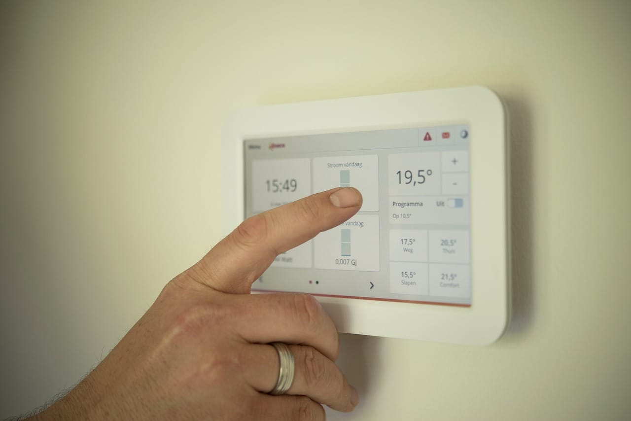
Whether you are building a new precision agriculture network or upgrading a legacy factory floor, the deployment of reliable rs485 temperature sensor monitoring is driven by one simple reality: the difference between guessing and knowing.
Putting sensors across an expansive industrial environment poses a fundamental networking problem: how do you physically and logically connect scattered field-level RS485 nodes to a central Ethernet-based SCADA control room? Temperature and humidity aren’t just nice to track; they directly determine yield, disease pressure, and operational efficiency. In greenhouses, temperature swings outside the optimal range can cut production by 30% or more.
If you are in the planning phase, face financial reality. By not having to physically inspect the scattered zones, you can save tons of man-hours and by automation of your agriculture IoT temperature monitoring setup, you can greatly reduce operating expenses. Use the calculator below to check your ROI.
The ROI is undeniable. However, figuring out how to connect RS485 to Ethernet without crashing the entire system is where both system architects and field engineers stumble. If you’re debugging an existing network that’s dropping packets or designing a brand new one, this guide explains the physical, protocol, and architectural challenges of routing telemetry data.
Architectural Planning: The “Plug and Pray” Fallacy
The biggest mistake beginners make in automation networking is to believe bridging serial data to Ethernet is merely a physical connection. It’s almost irresistible for DIY builders to buy a cheap $15 passive serial-to-ethernet cable, splice the twisted pairs, plug it into an RJ45 jack and hope for the best.
This approach fundamentally misunderstands the physical layer architectures involved:
| Specification | RS485 (Field Level) | Ethernet (Control Room) |
|---|---|---|
| Architecture | Half-Duplex (Only one device speaks at a time) | Full-Duplex (Simultaneous bidirectional traffic) |
| Topology | Daisy-chain (Linear Bus) | Star / Ring / Mesh |
| Data Handling | Raw byte transmission | Packetized TCP/IP routing |
| Max Distance | 1,200 meters (theoretical) | 100 meters (Copper) |
Because RS485 is a half-duplex daisy-chain, if two devices try to speak at the exact same millisecond, the electrical signals collide on the copper wire, resulting in corrupted data. Ethernet inherently assumes it can send data whenever it pleases. If you do not have an intelligent, active gateway acting as a traffic cop between these two entirely different physical realms, your network will crash continuously.
Protocol Collisions: Transparent Passthrough vs. True Translation
If you have already deployed your sensors and your SCADA dashboard is flashing “Bad Data” or “Device Timeout” errors, you have likely hit the protocol brick wall. This happens when facilities try to save budget by using “transparent” serial servers instead of genuine industrial gateways.
Here is the technical reality: Most industrial temperature sensors output data in Modbus RTU. Most modern SCADA systems and PLCs request data in Modbus TCP. These are not the same protocol.
A cheap “transparent” converter simply takes the Modbus RTU bytes from the sensor, wraps them blindly into a TCP packet, and fires it at the SCADA system. When the SCADA system unpackages the TCP payload, it expects to find a 7-byte MBAP header. Instead, it finds a raw RTU Slave ID and crashes. You do not need a passive data pipe; you need an active “bilingual translator.” By deploying a true modbus rtu to tcp gateway, the hardware intercepts the RTU packet, verifies the CRC, strips it, generates the correct MBAP header, and delivers a pristine Modbus TCP packet to your software.
The Delimiter Trap: Why Transparent Gateways Truncate Packets
There is a much deeper, incredibly frustrating bug that field engineers run into all the time with cheap gates. You might have a SCADA system that reads data perfectly 90% of the time, but occasionally throws a random CRC error and drops the connection.
This is often caused by the Hexadecimal Delimiter Trap. Cheap “transparent” serial-to-ethernet converters rely on a predefined delimiter byte—very commonly a Carriage Return (0x0D in hexadecimal) or a Line Feed (0x0A)—to know when an RS485 frame has finished transmitting from the sensor. Once it sees that byte, it packages the payload and sends it over TCP.
However, what happens if the analog temperature value from your sensor happens to equal `0x0D` in hex? The generic gateway sees that byte in the middle of the payload, falsely assumes the packet is done, and chops the Modbus frame in half. The SCADA system receives a prematurely truncated frame missing the CRC checksum, causing a silent failure. Proper industrial gateways do not rely on dumb delimiter characters; they actively parse the Modbus length to ensure data integrity.
Step-by-Step Software Configuration
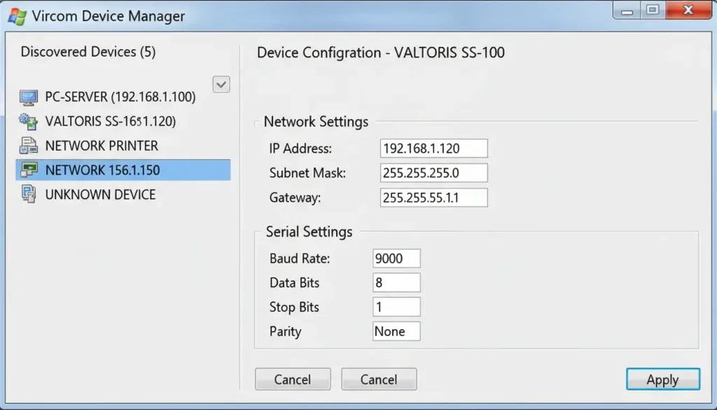
Bridging this protocol gap is easily done with a professional configuration utility (like Valtoris’ Vircom) and you won’t have to write custom parsing scripts:
- Set the IP address: By default, gateways use DHCP. Assign a static IP (e.g., 192.168.1.188) to ensure your SCADA never loses the connection path.
- Configure serial parameters: Exactly match what your sensor needs (e.g. 9600 baud, 8 data bits, 1 stop bit, no parity).
- Enable Modbus Gateway Mode: This is the critical step for troubleshooting data truncation. Do not leave the device in “Transparent/None” mode. Select “Modbus TCP to RTU” to enable active, length-aware protocol translation.
Surviving the Polling Crash: Balancing Gigabit SCADA with 9600 Baud Sensors
Once you solve the protocol translation, you run into the speed mismatch. Modern SCADA systems running on gigabit fiber optic backbones are aggressive. They are designed to query data every 100 milliseconds.
However, field sensors are slow. If you have 20 temperature sensors daisy-chained on a single RS485 bus running at 9600 baud, the physical transmission time required to ask Sensor 1 for its temperature, wait for its reply, and then move to Sensor 2 is substantial. Polling 20 nodes takes about 1 to 2 seconds to complete the loop.
If your SCADA system sends 20 requests in 100 milliseconds, the RS485 bus will flood, collisions will occur, and the gateway will drop the connection, resulting in a system-wide polling crash.
Industrial-grade serial servers solve this through “Storage Polling” (Edge Caching). Instead of letting the SCADA directly interrogate the slow sensors, the serial server autonomously polls the sensors continuously at a safe, stable 9600 baud. It stores the live temperature data in its own high-speed RAM. When the SCADA queries the server at Gigabit speeds, the server instantly replies from its RAM cache in sub-3 milliseconds.
Failsafe Biasing vs. Termination: Preventing Idle State Crashes
Many engineers are taught to terminate an RS485 bus with a 120 ohm resistor at the furthest end to prevent signal reflection over long distances. But field technicians often say that putting this resistor on crashes the entire network.
The reason lies in the bus’s idle state. A 120 ohm resistor is a heavy load on the copper wires. When no sensor is actively transmitting, the voltage difference along the A and B lines is greatly reduced. If it dips below 200mV then the bus receivers cannot distinguish between a valid signal and random electrical noise . This causes a significant number of framing errors.
To accomplish this, the network requires Fail-safe Biasing (pull-up and pull-down resistors) to set the idle bus voltage into a known, stable state. These resistors can be calculated and soldered outside, but modern industrial gateways have internal fail-safe transceivers and switchable bias resistors, so there’s no need for this complex electrical balancing act during commissioning.
Ground Loops and EMI: Protecting Analog Temperature Accuracy
Hardware reliability in the field is vastly different from a clean laboratory setup. Factory floors and large agricultural pumping stations are filled with Variable Frequency Drives (VFDs) and massive motors that induce severe Electromagnetic Interference (EMI) onto copper wires.
The RS485 standard is theoretically good for 1200m . But run unshielded cables parallel with high voltage equipment and you will mutate 0s into 1s and corrupt your temperature telemetry .
Furthermore, when sensors are distributed across large physical distances, variations in ground potential occur. If Sensor A is grounded in a building with a slightly different voltage potential than the serial server in Building B, a “Ground Loop” forms. Unwanted current will travel down the RS485 data lines, severely skewing analog temperature readings and eventually burning out the communication chips.
To prevent ground loops and EMI destruction in harsh environments, a standard serial server alone is not enough. You must deploy an Isolated RS485 Hub (featuring 2500V Galvanic Opto-Isolation) upstream of your serial device server. This hub physically separates the copper field wiring from the server using light-based signal transfer, protecting your entire IP network from field surges.
Quick Reference: Pinout for Common Connections
| Interface | Signal | DB9 Pin | Suggested Wire Color |
|---|---|---|---|
| RS232 | TX / RX | 2 / 3 | Yellow / Green |
| RS485 | A(+) / B(-) | – | White / Blue |
| RS485 | GND | – | Black (optional) |
The Multi-Master Conflict: Sharing Sensor Data Between SCADA and Local HMIs
As you scale from a pilot project to a full production deployment, a new architectural hurdle arises: The Multi-Master Conflict. Often, operators need to view the exact same temperature sensor data on a localized HMI touchscreen bolted to the greenhouse control cabinet, while the centralized modbus temperature sensor iot platform simultaneously polls that same sensor for historical logging.
Native RS485 is strictly a Single-Master bus. If the local HMI and the Cloud SCADA send a Modbus request at the same time, the queries collide on the wire. Standardizing your deployment using a multi-host capable rs485 to ethernet converter resolves this. An advanced gateway accepts simultaneous incoming TCP requests from the local HMI and the remote SCADA, queues them intelligently, arbitrates the physical RS485 bus, and returns the answers without any collisions.
Prove It Works: Real-World Sensor Deployments
These architectural designs aren’t theoretical. Buying industrial-grade hardware rather than splicing DIY cables pays off immediately in uptime and yield optimization.

Case 1: Henan Province, China – Cotton Farm
A cotton farm deployed 50 soil moisture and temperature sensors across 1,000 acres. Sensors were connected via RS485 to an 8-port serial server, which fed data to a centralized cloud platform. By improving the timing of planting, they were able to reduce irrigation water use by 35% and increase yield by 15% using precise, isolated data.
Case 2: India – ICAR Remote Monitoring System
The Indian Council of Agricultural Research (ICAR) developed a solar-powered monitoring system for remote farms lacking hardwired electricity. Using low-power RS485 sensors and cellular-enabled serial servers, they established reliable telemetry backhaul over mobile networks, proving the viability of off-grid edge gateways.
Hardware Checklist: Selecting the Right Edge Gateway
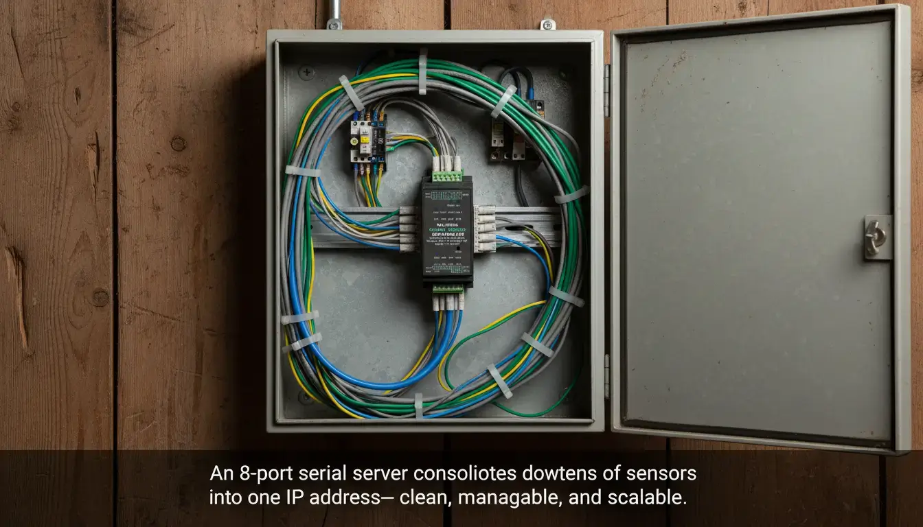
Building a robust agriculture iot temperature monitoring system isn’t about buying the most expensive sensors; it’s about securing the data pipeline. When procuring an edge gateway, enforce this definitive checklist to ensure you are buying an industrial tool rather than a hobbyist toy:
- True Protocol Translation: Must feature native Modbus RTU to TCP conversion.
- Edge Caching / Storage Polling: Mandatory for preventing bus crashes when integrating with modern SCADA.
- Failsafe Transceivers: Look for internal bias resistors to stabilize the idle network state.
- High-Voltage Isolation: Optional 2500V-3000V isolation for protecting your PLC from ground loops.
- Multi-Host Support: The gateway should support multiple TCP connections at the same time.
- Industrial Form Factor: Operating range -40°C to 85°C, DIN rail mount.
| Application Scenario | Sensor Count | Topology Limitation | Recommended Hardware | Action |
|---|---|---|---|---|
| Single Furnace / Machine | 1 – 15 nodes | Linear daisy-chain | 1-Port Serial Server Compact DIN-rail, wide voltage | View VT-1CH Specs → |
| Distributed Floor (Scattered) | 15 – 50 nodes | Forced Star Topology | 4-Port RS485 Hub + Server Optically isolated branch splitter | View Hub Solution → |
| High-Speed Real-time SCADA | 50+ nodes | Parallel multi-bus | 8-Port Serial Gateway Multi-channel parallel polling | View 8-Port Gateway → |
Need an Engineer to Verify Your Sensor Wiring Topology?
Not sure if you need optically isolated RS485 hubs, terminating resistors or plain serial servers on your factory floor? Enter the number of nodes and the physical distances below. Our application engineers will review your layout and send you a verified hardware architecture recommendation within 24 hours.
