

Switch debounce is a major engineering problem . A single actuation of an industrial limit switch rarely results in a single clean electrical signal. What looks like a switch simply closing to the naked eye appears as a chaotic storm of dozens of rapid-fire pulses to a microsecond-scanning PLC, registering the microscopic rebounding of metal contacts. Immediate results are random SCADA alarms, inflated high speed counter values and unpredictable machine interlocks.
Industry practice has been to patch this physical defect on the software layer with ladder logic timers (TON/TOF). But fixing mechanical hardware faults with software logic is basically inefficient. It bloats PLC memory, artificially inflates scan times, and often breaks down when mixed with real world electromagnetic interference (EMI).
Mechanical problems require isolation at the hardware level. The physics of contact bounce, the architectural cost of software filtering, and why true hardware debounce is the most robust engineering standard are covered in this guide.
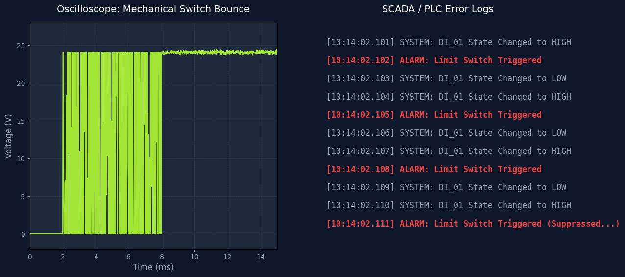
Table of Contents
The Physics of the Bounce: Why Your Switch Triggers 50 Times
To fix a problem, we must understand its physical root. Inside every limit switch, relay, or contactor, there are metal spring contacts. When a mechanical force pushes them together, they do not simply mate and stop. They collide, deform slightly, and physically rebound off each other microscopically before finally settling.
According to authoritative hardware engineering guidelines published by institutions like Analog Devices, this mechanical chatter generates a series of high-speed voltage spikes. During this settling period, the electrical connection opens and closes repeatedly.
| Switch Type | Average Bounce Duration | Risk of Phantom Triggers |
|---|---|---|
| Standard Push Buttons | 5 ms to 20 ms | High (Depends on operator force) |
| Heavy-Duty Limit Switches | 10 ms to 30 ms | Very High (Vibration exacerbates bounce) |
| Electromechanical Relays | 5 ms to 15 ms | Medium (Inductive kickback also present) |
| Optical/Solid State Switches | < 0.1 ms | None (No moving parts) |
If your PLC has a scan time of 2 milliseconds, it is fast enough to “see” every single one of those microscopic bounces as an intentional command. If that Digital Input (DI) is tied to a high-speed pulse counter, your production count will be ruined instantly.
The Trap of Software Debounce (Ladder Logic Timers)
When a junior automation engineer sees a bouncing limit switch on the floor of the factory, their first instinct is usually to open their PLC programming software (TIA Portal, Studio 5000, etc.) and drop in a Timer.
The logic is simple: “If the input turns ON, wait 50 milliseconds. “If it is still ON after 50ms then it is a real signal not a bounce.”
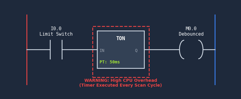
While software debouncing works perfectly on a test bench, it creates a massive architectural bottleneck when scaled across a complex industrial facility.
| Debounce Approach | Implementation Effort | PLC CPU Impact (Scan Time) | Scalability |
|---|---|---|---|
| PLC Software Timers (Ladder Logic) | High (Must code each input individually) | Severe (Timers must be evaluated every scan cycle) | Poor |
| Hardware Filtering (Edge I/O) | Zero (Check a configuration box once) | None (Processed outside the PLC) | Excellent |
The Industrial Reality: Mixed EMI and Bouncing
In a laboratory, a 50ms software timer works perfectly to fix a bouncing switch. However, factory floors are not laboratories. In a real industrial plant, the wire connecting your limit switch to your central PLC cabinet might be 100 meters long, running parallel to high-power motor cables.
This creates an engineering nightmare: The Antenna Effect. Long cables absorb electromagnetic interference (EMI) from Variable Frequency Drives (VFDs). (Just like analog signals suffer from voltage drops—see our guide on fixing 4-20mA interference—digital signals are easily corrupted by this noise.) When EMI spikes mix with mechanical switch bounce, software algorithms struggle to differentiate between a legitimate contact closure, a mechanical bounce, and random electrical noise.
| Underlying Hardware Design | Debounce Mechanism | EMI Protection |
|---|---|---|
| Direct PLC Wiring (No Filter) | None (Relies on software) | Poor |
| Basic RC Filter Circuit | Capacitor smooths the voltage curve | Medium |
| RC Filter + Schmitt Trigger | Hardware hysteresis snaps the signal clean | High |
| Smart Edge MCU (Hardware filtering) | Microcontroller drops spikes < 50ms instantly | Maximum (Digitized at source) |
The Ultimate Fix: Zero-Code Hardware Debounce at the Edge
You already know software timers drain your PLC CPU, and building custom RC-filter circuits from scratch is not viable for a large-scale factory. The practical solution is to push this computational burden to the edge—resolving physical defects directly at the source without writing a single line of code.
This is where remote IO modules come in. By deploying dedicated I/O controllers equipped with built-in optocouplers and MCU-level hardware filtering, you eliminate the mechanical bounce and EMI spikes before they ever reach your industrial network. (This is exactly the architectural approach we use at Valtoris).
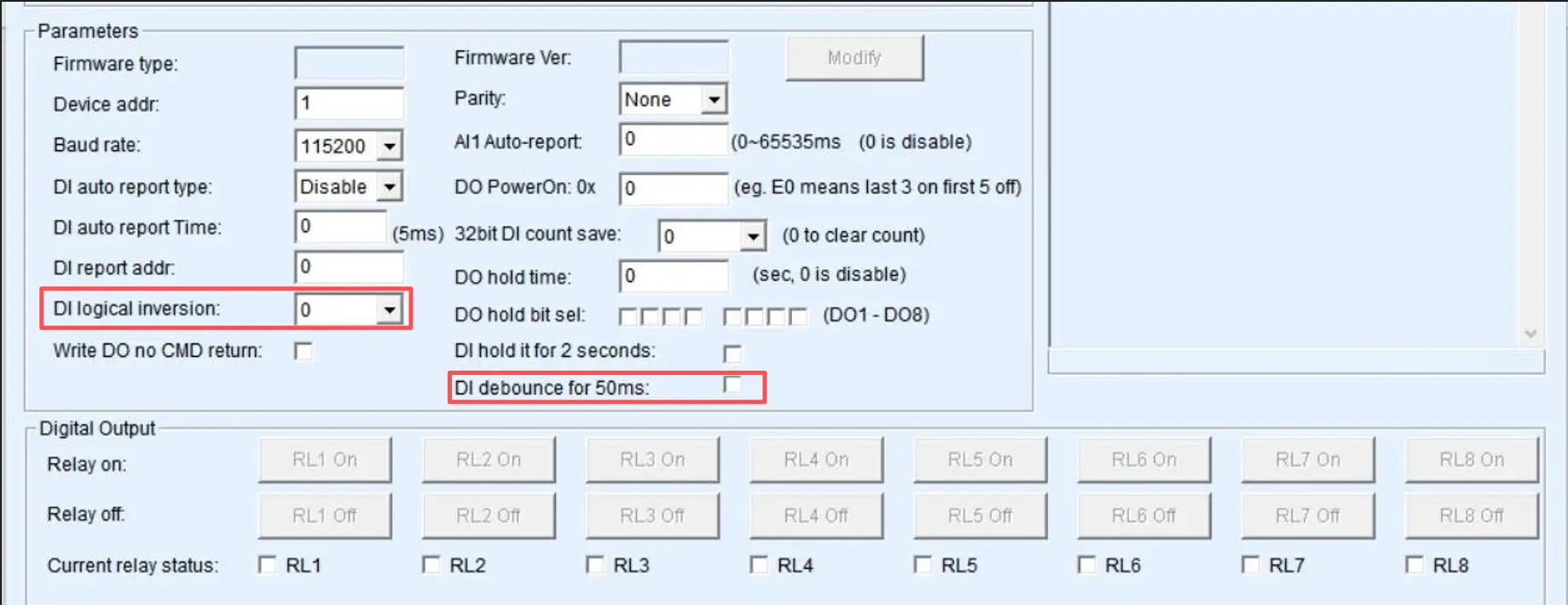
Instead of writing and managing dozens of TON/TOF logic blocks, engineers simply define the hardware filter value (e.g., 50ms) during the initial device setup via the VirCOM utility. Once configured, the hardware’s physical pins intercept the raw signal. Any erratic fluctuations occurring within that 50-millisecond window are silently and autonomously absorbed by the edge module.
The central PLC is never affected. It receives a clean, mathematically perfect data packet (Modbus TCP, PROFINET or EtherNet/IP) that represents a perfect “1”. This architectural change makes ladder logic so much easier and provides solid SCADA logging across any major control ecosystem.
| Symptom on SCADA / PLC | Root Physical Cause | Does Edge Hardware Debounce Fix It? |
|---|---|---|
| Rapid, random alarm toggling (ON/OFF) | Mechanical Switch Bounce | Yes. 50ms filter eliminates it entirely. |
| Counter registers 5 parts instead of 1 | Contact Chatter | Yes. Only one clean pulse is sent to the PLC. |
| Signal stays stuck ON | Welded Relay Contacts / Wire short | No. This requires physical replacement. |
| Missing high-speed encoder pulses | Filter window is too large | Warning. Do not use 50ms debounce on >20Hz signals. |
Summary: Stop Fighting Physics with Software
Software debouncing costs nothing, but it creates a huge amount of long-term technical debt in your PLC architecture. Using remote i/o devices with embedded hardware filtering you decouple the dirty electrical reality of the factory floor from the pristine digital world of your control system.
| Your Application Scenario | Recommended Debounce Strategy |
|---|---|
| PCB Design / Microcontroller Projects | RC Filter + Schmitt Trigger Hardware |
| Small Machine, 2-3 Switches, Budget Constrained | PLC Software Timer (Ladder Logic) |
| Industrial Automation / SCADA Upgrades | Edge Remote I/O Modules (Built-in hardware filter) |
Integration Note
If your system is also struggling with analog signal drops over long distances, combining hardware digital debounce with edge analog digitization is the ultimate upgrade path. (Learn more in our guide on resolving analog voltage drops).
Engineering Trade-offs: When NOT to use Remote Edge I/O
While shifting I/O to the edge resolves most bouncing issues, standard remote I/O modules are not a universal fix. Avoid edge hardware debouncing in these specific scenarios:
- Safety & E-Stop Circuits: Transmitting DI status over Ethernet (TCP) or 4G (LTE) introduces inevitable network polling latency. Never use standard remote I/O for E-Stops, Safety Light Curtains, or hard-interlocks requiring microsecond response times. Wire these directly to dedicated safety PLC I/O.
- High-Speed Encoders: To ensure industrial stability, our edge modules feature a hardcoded 10ms hardware debounce filter. This restricts physical pulse capture to a maximum of ~50Hz. Do not use standard DI modules for reading 1kHz+ servo incremental encoders; use dedicated high-speed counter modules instead.
- Heavy Inductive Loads: The integrated DO relays are rated for a maximum of 5A (250V AC / 30V DC). Do not wire them directly to large industrial motors or heavy solenoid valves. For heavy inductive loads, you must use intermediate relays or AC contactors to prevent inrush currents from welding the internal contacts.
- Voltage Compatibility: The DI wet nodes support a maximum of 24V DC input. If your legacy system relies on 220V AC digital signals, you must install an optocoupler isolation module upstream. Never connect high voltage AC directly to the DI terminals.
- Cost & Architecture Scale: If your equipment is a completely isolated micro-machine (e.g., just 2-3 limit switches) that will never integrate into a plant network or SCADA system, deploying dedicated edge I/O is not cost-effective. For these isolated “islands,” using basic PLC TON timers is more economical. However, for full production line digital upgrades, edge filtering is the mandatory architectural standard.
Typical Application Scenario: Packaging Line Upgrades
The Problem: When retrofitting legacy packaging conveyors, engineers often route mechanical limit switches past large VFDs (Variable Frequency Drives). The combination of mechanical bounce and EMI noise causes older PLCs to register ghost triggers, stopping the line randomly.
The Edge Solution: Instead of writing complex software timers and adding RC filters to the main control cabinet, engineers deploy our Smart Edge I/O nodes directly next to the limit switches. By setting a 30ms hardware filter in the VirCOM utility, all physical bounce and EMI spikes are absorbed locally. The central PLC receives only clean, validated state changes over Modbus TCP, eliminating false stops immediately. By preventing random line stops and reducing PLC debugging time, these edge modules typically pay for themselves within the first month of operation.
Resolve Contact Bounce at the Hardware Layer
Valtoris Smart Edge I/O modules feature native optocoupler hardware filtering. By configuring the DI filter via the VirCOM utility, erratic switch chatter and EMI spikes are resolved at the edge, delivering stable Modbus TCP/RTU signals directly to your PLC.
Frequently Asked Questions (Switch Debouncing)
Can I just solder a capacitor across the switch instead of changing my PLC code?
Soldering a capacitor (a simple RC filter) slows down the voltage transition and absorbs some high frequency spikes, but it doesn’t give you a sharp ON/OFF threshold. Without a Schmitt Trigger to square up the curve, a slow rising voltage can cause digital logic gates to oscillate, potentially creating even more spurious triggers. Industrial edge I/O modules come with complete filtering circuitry built in.
Why does my software debounce logic work on the test bench but fail on the factory floor?
On a test bench, you are only dealing with pure mechanical bounce. On a factory floor, unshielded wires running long distances act as antennas, picking up electromagnetic interference (EMI) from heavy machinery. If an EMI spike occurs just as your software timer finishes, the PLC will misinterpret the noise as a valid signal. Hardware isolation and filtering are required to block EMI before it reaches the digital logic layer.
Does a 50ms hardware debounce delay ruin high-speed pulse counting?
Yes. If you are reading data from a high speed device, such as a flow meter or rotary encoder that outputs pulses at 100Hz, a 50ms debounce filter will just eat all the legitimate pulses. Hardware debouncing should be enabled only on manual push-buttons, mechanical relays and slow moving limit switches. For high-speed applications, refer to our guide on Modbus pulse counter integration.
How do I debounce an optical limit switch or proximity sensor?
Solid-state devices like optical or inductive proximity sensors have no moving mechanical contacts, so they do not suffer from physical “bounce.” However, they can experience “chatter” if the target object is vibrating precisely at the detection threshold. While you generally don’t need a heavy 50ms debounce, a small 5ms hardware filter can help stabilize vibrating targets.
Is a TON (Timer On Delay) or TOF (Timer Off Delay) better for ladder logic debouncing?
Usually a TON is preferred to ensure that a signal is intentionally activated (i.e., making sure a button is really pressed before starting a motor). A TOF is used to stretch a signal to prevent the system from accidentally shutting down on a momentary bounce loss. But running both timers for multiple switches quickly eats up PLC memory. The best architecture is to push this logic down to a remote io module.
What happens if my bouncing limit switch is connected via a 100-meter wire?
Long wires have a high intrinsic capacitance and resistance. This may increase the mechanical bounce time and make it more sensitive to voltage drops. Pulling 100 meters of vulnerable copper wire back to a central PLC is not best practice. The best practice is to digitize the dry contact signal locally with a remote module and send the data securely over Ethernet. (See our dry contact over Ethernet guide).
How do I handle contact bounce on an AC 220V mechanical contactor?
Standard edge I/O modules typically accept 24V DC wet nodes. To debounce a 220V AC contactor, you cannot wire it directly to the DI terminal. You must route the 220V signal through an intermediate isolation relay to convert it to 24V DC. Once converted, the edge module’s hardware filter will seamlessly absorb the mechanical chatter of the intermediate relay.
Will enabling a hardware debounce filter delay my SCADA alarm response time?
Yes. There is a physical filter, the Modbus register is updated at the end of the debounce period. But in typical SCADA monitoring over Ethernet or LTE, the network polling cycle itself is often 100ms to 250ms. Any localized hardware delay is absorbed in this network polling window and is functionally invisible to the operator. Furthermore, the risk of alarm flooding is completely eliminated.