
A severed network connection can cause standard Ethernet relays to freeze in their last commanded state, leading to runaway equipment, product loss, or hazards. This technical guide explains how upgrading to industrial Edge I/O with native Watchdog timers automatically forces machinery to a safe shutdown the millisecond communication drops—protecting your physical assets without requiring complex PLC programming.
In industrial automation, controlling physical actuators over an IP network using an Ethernet relay creates a critical vulnerability: the disconnect trap. Both the HTTP and Modbus TCP protocols are state-driven. The edge relay executes and holds that physical state until explicitly told otherwise by the central SCADA system sending out a “ON” command.
If the network link is lost because of damaged fiber optics, crashed switches or too much EMI, the central controller is blind. However, typical commercial Ethernet relays do not possess autonomous awareness. They stay in the last state they were commanded to be in. For equipment like dosing pumps, heating elements or motorized valves, this latched condition means uncontrolled equipment running away.
Even in simple commercial automation, following the basics of functional safety principles (like IEC 61508) ensures that your system will go to a safe state when communication is lost. A fail safe relay architecture is not an optional feature, but a basic requirement to prevent equipment damage and costly accidents.
- 1. The “Disconnect Trap”: Why Standard Relays Freeze
- 2. 3 Architectures for Failsafe Remote Control
- 3. Configuring the “DO Hold Time” (Watchdog)
- 4. Power-On Safety: Surviving a Total Facility Reboot
- 5. Practical Verification: 5-Minute Fail-Safe Bench Test
- 6. Conclusion: Never Trust the Network
- 7. Frequently Asked Questions
The “Disconnect Trap”: Why Standard Relays Freeze
Ethernet and Modbus TCP protocols are fundamentally “state-driven.” The control system pushes a state (e.g., DO = 1) to the edge device. The edge device assumes this state is absolute until it receives a new instruction. Standard commercial IoT relays act as passive listeners. They possess no self-awareness regarding the health of the network infrastructure.
| Relay Type | Network Status | Relay Behavior on Network Drop | Consequence |
|---|---|---|---|
| Standard IoT / HTTP Relay | Disconnected | Freezes in Last State (Latched) | Critical Danger (Runaway Equipment) |
| MQTT Relay (Basic) | Disconnected | Freezes in Last State | Critical Danger |
| Industrial Failsafe Relay | Disconnected | Reverts to Pre-defined Safe State | Safe Shutdown |
3 Architectures for Failsafe Remote Control
According to functional safety guidelines (such as those outlined in IEC 61508 / ISA-84 principles), control systems must default to a safe state upon the loss of communication. To achieve this over an Ethernet network, engineers generally deploy one of three architectures.
Option A: Hardware Interlock (Time Relay)
In this traditional approach, engineers wire a standard network relay in series with a physical pneumatic or electronic Time Delay Relay (TDR). The SCADA system pulses Channel 1 every 2 seconds to keep the TDR energized. Channel 2 controls the actual pump. If the network drops, Channel 1 stops pulsing, the TDR times out, and it physically drops the power to the pump.
- Pros: Extremely robust and physically isolated.
- Cons: Doubles wiring complexity, consumes panel space, and adds mechanical failure points.
Option B: Local Touch Screen (HMI) Heartbeat
Instead of a passive relay, a local HMI or touch screen is installed at the remote site. The central cloud platform or master controller writes to a specific register every second. The local HMI runs internal scripts: if the register hasn’t updated in 3 seconds, it triggers an emergency stop sequence.
- Pros: Highly customizable (can sequence shutdowns).
- Cons: High cost and complexity. Requires writing and maintaining secondary logic scripts on the local screen.
Option C: Edge I/O with Hardware Watchdog (DO Hold Time)
This is the modern industrial standard. You utilize a smart Edge I/O module equipped with a built-in MCU watchdog. The module natively monitors the Modbus TCP stream. If communication ceases, the silicon-level watchdog takes over and forces the relays to a predetermined state.
- Pros: No PLC programming required at the edge. Wiring is as simple as a basic relay, but it yields PLC-level safety.
- Cons: Logic is hardcoded (it opens the relay instantly, rather than executing a complex timed shutdown).
Option D: Peer-to-Peer (P2P) Hardware Linkage (No Server Required)
For practical projects like remote water tank level control, a central server might not exist. You can pair two smart I/O modules directly over an Ethernet or cellular link.
When you combine Active DI Reporting on the sensor side with the DO Hold Time watchdog on the pump side, you have a robust P2P interlock. If the sensor module goes to sleep, or the network link goes down, the pump side no longer receives the heartbeat. The DO Hold timer expires and the pump safely shuts down without the need for a central controller.
- Pros: Extremely cost-effective. Eliminates the need for a central server, PC, or master controller.
- Cons: Logic is direct (1-to-1 mapping) and cannot execute complex conditional scripting.
| Architecture | Hardware Cost | Programming Required | Panel Footprint |
|---|---|---|---|
| Time Relay Interlock | Medium | Low (SCADA pulse only) | Large (Extra relays) |
| Local Micro-PLC | Very High | High (Remote Ladder Logic) | Large |
| Smart Edge I/O (Watchdog) | Low/Medium | Zero (Configuration Checkbox) | Small |
Configuring the “DO Hold Time” (Watchdog)
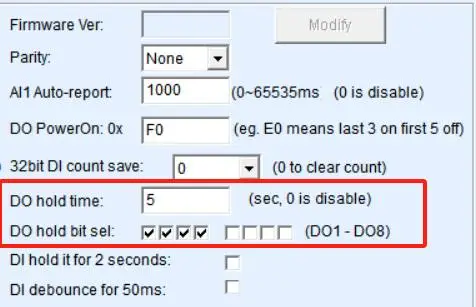
If you opt for an industrial Edge I/O module, enabling the hardware watchdog requires zero coding. You can easily configure it using the free VirCOM utility software via a simple graphical interface, which writes the parameters directly to the module’s flash memory.
Modbus Register Reference (Advanced Users)
| Parameter | Hex Address | Data Format | Description |
|---|---|---|---|
| DO Hold Time | 0x0047 | UInt16 (Seconds) | 0 = Disabled, 1-65535 = Timeout duration |
| DO PowerOn State | 0x0044 | UInt16 (Bitmask) | Bit 0 = DO1, Bit 7 = DO8 (1 = ON, 0 = OFF) |
If a value is entered in the DO Hold Time Time field (for example, 3 seconds), the module will generate a countdown timer. The timer is reset every time a Modbus TCP command is received. If a valid command is not received within 3 seconds, the module will automatically clear the digital outputs specified.
Why “Fail-Safe” Doesn’t Always Mean “Off”
If you are controlling a heating element, the safe state on network loss is absolutely OFF. But what if you are controlling a greenhouse exhaust fan or server room ventilation? The safest state is to keep it running. Advanced modules feature DO Hold Bit Selection, letting you define exactly which relay channels are subjected to the watchdog countdown. For devices that must remain energized during a network drop, simply exclude them from the hold bits and wire them to the relay’s Normally Closed (NC) terminal.
| Equipment Type | Failsafe Goal | Required Watchdog Action (Network Loss) |
|---|---|---|
| Dosing Pump / Motor | Prevent Overflow / Spills | Force Relay OFF |
| Industrial Heater | Prevent Fire / Overheating | Force Relay OFF |
| Greenhouse / Room Ventilation | Prevent Overheating | Wire to NC (Normally Closed) Terminal |
| Magnetic Door Lock | Ensure Life Safety Egress | Force Relay OFF (De-energize) |
Power-On Safety: Surviving a Total Facility Reboot
Network disconnections are often the byproduct of a larger facility issue: a total power outage. When the facility’s power is restored, a new, highly dangerous vacuum period begins.
A remote I/O module boots up in approximately 3 seconds. However, industrial Ethernet switches might take 60 seconds to negotiate, and the central SCADA PLC might take 2 minutes to fully load its program. What is the Ethernet relay doing during those 2 minutes?
If a cheap relay defaults to “ON” upon power-up, your equipment will run uncontrolled for 2 minutes before the PLC can connect and command it to stop. To survive a reboot, edge modules utilize a DO PowerOn State registry. Engineers can pass a hex value (e.g., 0x 00 to force all relays OFF, or 0x F0 to turn the first four OFF and the last four ON) that dictates the strict physical state of the relays the millisecond power is restored, bridging the gap until the PLC takes command.
| System Component | Typical Boot Time | System Status During Window |
|---|---|---|
| Edge I/O Module | ~ 3 Seconds | Active, relying on DO PowerOn State. |
| Managed Ethernet Switch | 45 – 90 Seconds | Network is down; SCADA commands cannot reach I/O. |
| Central PLC / SCADA | 1 – 3 Minutes | Logic engines booting; unable to control field devices. |
Objective Scope: Where Edge Watchdogs Are NOT the Right Fit
While hardware watchdogs (DO Hold Time) solve the vast majority of disconnect risks in commercial and industrial IoT, they are not a silver bullet for every scenario. You should look for alternative solutions if your project requires:
- Sequential Shutdown Logic: Edge I/O watchdogs execute a “hard snap” to a pre-defined physical state instantly. If your equipment requires a phased shutdown (e.g., “Turn off the heater, wait 45 seconds for cooling, then turn off the exhaust fan”), a passive I/O module cannot process this. You must deploy a local Micro-PLC at the edge (Architecture Option B).
- High-Speed Motion & Life Safety (SIL/SIS): milliseconds to seconds. For high-speed robotic arms, CNC machining, or highly volatile chemical environments where human life depends on sub-millisecond reaction times, standard Ethernet relays are strictly insufficient. You must use certified Safety Instrumented Systems (SIS) like GuardLogix or specialized EtherCAT safety nodes.
The Bottom Line: For controlling pumps, HVAC, commercial heaters, valves, and environmental controls, an Edge I/O watchdog is the most cost-effective fail-safe. For complex logic or explosive safety, stick to a PLC.
Practical Verification: 5-Minute Fail-Safe Bench Test
To clearly understand the equipment’s physical response during a network drop, we recommend bench-testing the edge watchdog mechanism independently before connecting live loads like dosing pumps or heaters.
Bench Test Setup
- Industrial Edge I/O Controller
- Standard DC 24V Power Supply
- PC running configuration software (e.g., VirCOM) and a Modbus client
- Digital multimeter with continuity beep function
* For engineers looking to replicate this test, download our complete wiring diagram and VirCOM quick start guide (PDF) here.
Step 1: Write the Watchdog Parameter
Open the configuration software, locate the device, and find the DO Hold Time parameter. Set it to 3 (3 seconds). Save the configuration and reboot the module.
Step 2: Simulate Normal Traffic
Set the multimeter to continuity mode and connect the probes to the NO (Normally Open) and COM terminals of DO1. Connect via Modbus TCP (default port 502) and command DO1 to close. The multimeter should beep continuously, indicating a closed physical circuit.
Step 3: The Disconnect Trap (Physical Network Cut)
While the PC continuously sends Modbus polling commands, physically unplug the Ethernet cable from the module. The module’s internal MCU immediately detects the silence on the TCP port. After exactly 3 seconds, the relay will physically click open, and the multimeter beep will stop. This proves the hardware watchdog autonomously forces the output to a safe state without requiring a central PLC command.
Step 4: Power-On Safety (Facility Reboot)
Network failures often accompany total power outages. In your configuration tools, ensure the DO PowerOn State (Register 0x0044) is configured to all-OFF. Cut the 24V power, then restore it. Monitor the multimeter during boot-up; the relay will strictly remain open. This proves the device stays physically locked in a safe state during the dangerous 2-minute vacuum period while the PLC or switch reboots.
Conclusion: Never Trust the Network
The golden rule of industrial automation over IP is simple: The network will eventually fail. Standard commercial Ethernet relays lack the hardware autonomy to survive this failure gracefully. By upgrading to industrial Edge I/O modules equipped with native watchdog timers (DO Hold Time) and definitive Power-On states, you embed PLC-grade safety directly into the physical edge, ensuring that a severed cable never results in a mechanical disaster.
| Failure Mode | Symptom | Edge Watchdog Intervention |
|---|---|---|
| Severed Ethernet Cable | Total link loss | Hold timer expires; safe state triggered instantly. |
| Switch Overload (Broadcast Storm) | Link light ON, but TCP traffic dropped | Modbus heartbeat fails; safe state triggered. |
| PLC Software Crash | Network healthy, but polling stops | Heartbeat fails; safe state triggered. |
| Total Facility Power Loss | Equipment turns off | DO PowerOn State dictates safe behavior upon restoration. |
Don’t wait for a runaway pump to test your network’s resilience.
Secure Your Remote Control Architecture
Do not trust your critical equipment to latched relays. Upgrade to our intelligent edge nodes featuring built-in hardware watchdogs and Power-On state management. These CE-certified fail-safe modules provide diverse I/O configurations from compact to high-density, fully covering wired Ethernet, Wi-Fi, and 4G LTE cellular networking environments.
Frequently Asked Questions
Can I just rely on standard TCP Keep-Alive instead of an application-level watchdog?
No. TCP Keep-Alive only verifies if the low-level network socket is open. It does not guarantee that the SCADA application is actually running, processing logic, or sending Modbus commands. If the PLC software crashes but the OS network stack remains active, TCP Keep-Alive stays valid, but your relays will freeze. An application-level watchdog (DO Hold Time) directly monitors the actual Modbus polling stream, making it vastly more reliable for functional safety.
Can I use MQTT’s Last Will and Testament (LWT) instead of a hardware watchdog?
No. MQTT Last Will and Testament is a broker-side feature. If an MQTT relay drops offline, the broker will publish the LWT message to alert the SCADA system or other subscribers that the device is dead. However, this does nothing to physically open the relay at the edge location. The relay will remain latched. You must have a local hardware watchdog on the relay itself to physically cut the power.
What happens if the network is highly unstable and constantly connects and disconnects (network flapping)?
If your network experiences severe flapping, setting a tight watchdog timeout (e.g., 1-2 seconds) will cause “nuisance tripping,” where your equipment constantly starts and stops, potentially damaging motors. In these environments, you should use the calculator above to increase the DO Hold Time to absorb the jitter, or investigate the root cause of the EMI/packet loss before running critical outputs over that specific link.
When the network is finally restored after a disconnect, does the relay automatically return to its previous state?
It depends on your SCADA logic. The edge module itself acts passively once communication is restored. It will remain in its safe state until the SCADA system reconnects and actively sends a new Modbus command (e.g., Force Coil 0x05) to change its state. The I/O module does not “remember” the pre-crash state; it relies on the master controller to dictate the correct action upon recovery.
Do I need a watchdog timer for reading Digital Inputs (DI)?
Generally, no. If a network drops, the SCADA system simply loses visibility of the sensor state (the data goes “stale”). The danger lies in Digital Outputs (DO), where a physical machine is being driven. However, for highly sensitive inputs, edge modules can employ hardware debouncing to ensure the data sent prior to a drop was absolutely accurate.