
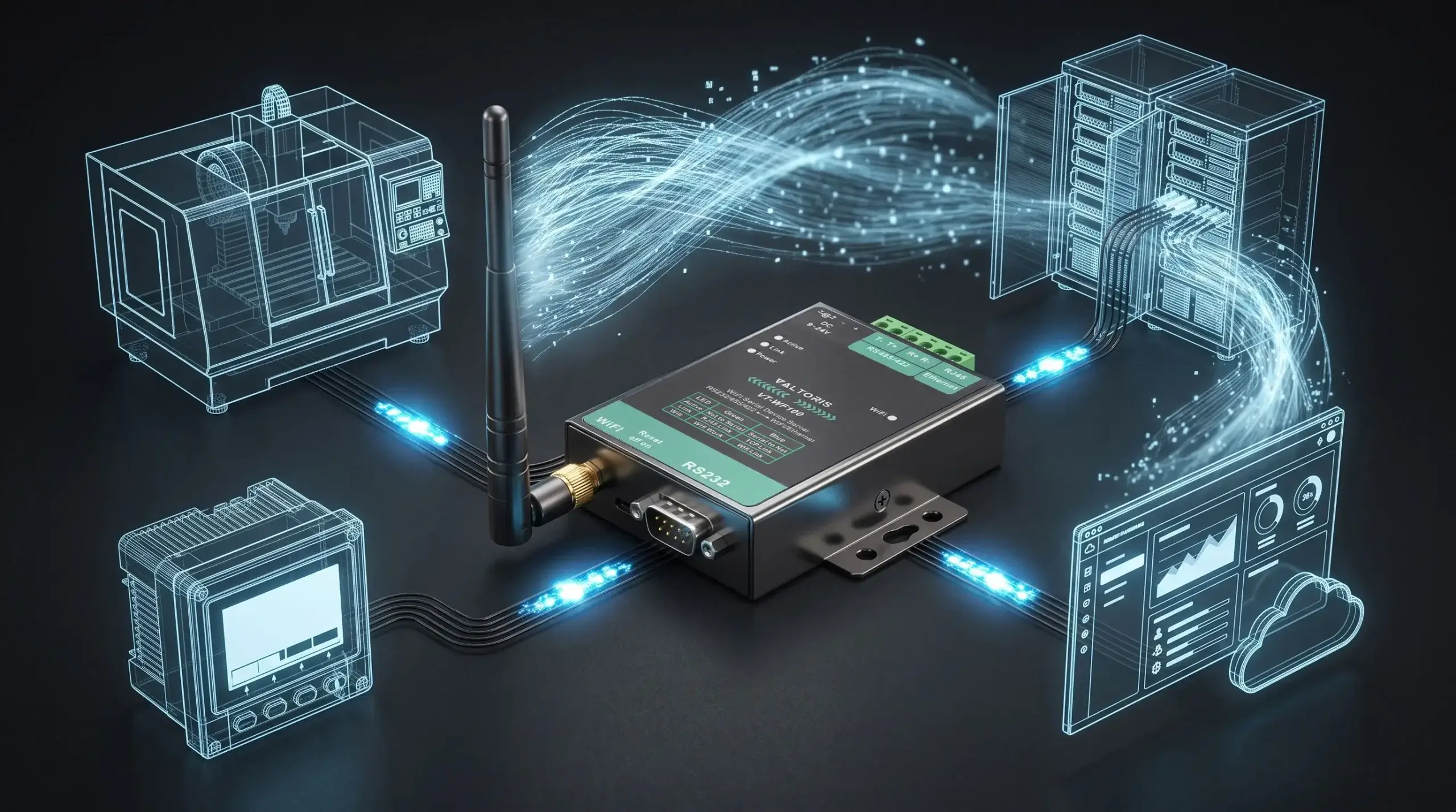
Going beyond basic configuration is also often effective wireless bridge troubleshooting at a solar site. You may have experienced RS485 wireless bridge connections breaking, Modbus RTU data becoming garbled, or devices rebooting unexpectedly. The root cause is often more related to the physical environment than to software settings.
Solar arrays face unique communication challenges, including high frequency electromagnetic interference (EMI) from string inverters, ground loop voltages across large sites, and complex RF barriers. This guide offers a simple, field-tested diagnostic methodology that helps engineers systematically isolate and fix these physical and network layer failures.
- Quick Diagnosis: Find Your Problem in 30 Seconds
- 1. The Power Problem: It Is Not Just About Voltage
- 2. The Silent Killer: Ground Loops & EMI
- 3. The Configuration Trap: It’s Not Just an IP Address
- 4. The Wireless Mirage: Signal Quality & Physical Barriers
- 5. The “Ping Works, But SCADA Fails” Dilemma
- 6. Choosing the Right Device for the Job
- 7. The Point-to-Point Diagnostic Checklist
- 8. The Permanent Fix: Upgrading the Hardware Layer
- 9. When to Abandon Wireless: The Fiber Alternative
- Frequently Asked Questions
Quick Diagnosis: Find Your Problem in 30 Seconds
🛠️ Interactive Diagnostic Wizard
Select the symptom you are experiencing on-site to instantly locate the cause:
If you’re still not sure, just start at the top—the most common failure point is power, and it’s often overlooked.
1. The Power Problem: It Is Not Just About Voltage
You connected a 12V supply to the circuit, and the LED lit up. That is good, right? Not necessarily.
What you’ll see: The bridge keeps restarting. This often happens at dawn or dusk, exactly when the inverter’s cooling fan turns on. Data logs show gaps at those times.
Why it happens: The power line experiences voltage drops or high-frequency electrical noise. Long thin wires and the inverter’s startup current cause this. Cheap wall adapters don’t regulate output well under load; when the fan kicks in, the voltage sags just enough to trigger a hardware reboot.
How to fix it
- Use a Regulated, Industrial SMPS: Don’t repurpose a random adapter. Use a dedicated switch-mode power supply designed for 9-24V DC with stable output.
- Localize Power: Keep the power supply close to the bridge. If running wire, use a gauge thick enough to prevent voltage drop over distance.
- Consider Isolation: In electrically noisy environments, a small, isolated DC-DC converter between your main supply and the bridge cleans the power perfectly.
2. The Silent Killer: Ground Loops & EMI
Your wiring is fine, but the data is a mess of garbled characters, or the communication is very sporadic.
The Failure: Random communications errors, checksum failures in your Modbus data, or total lock-ups that only recover after a physical power cycle.
The Root Cause
- Ground Loops: If your string inverter and data acquisition cabinet are grounded at different potentials (especially over long distances), a voltage difference exists. This drives current through the shield of your RS485 cable, inducing noise directly onto the data lines.
- Electromagnetic Interference (EMI): The inverter is a powerful source of high-frequency switching noise. A wireless bridge with a plastic case sits completely unprotected in this field, scrambling its internal logic.
How to fix it
- Single-End Shielding: When using an RS485 cable, only connect the shield at one end (usually the ground terminal of the bridge). Do not connect the shield at the inverter end. This breaks the ground loop.
- Use Proper Cable: Always use shielded, twisted-pair cable for the RS485 run. The twist cancels electromagnetic noise; the shield contains it.
- Demand Metal Enclosures: The bridge’s metal housing acts as a Faraday cage, blocking external EMI. Built-in surge protection on the RS485 port clamps high-voltage noise spikes from the inverter.
3. The Configuration Trap: It’s Not Just an IP Address
You can ping the device, but your SCADA system shows nothing. The device is practically invisible to your monitoring software.
The Failure: The network link is up, but no telemetry data flows.
The Root Cause: A mismatch in the communication stack. You’ve configured the IP layer, but the protocol layer is wrong. The bridge is passing bits, but failing to translate them correctly between the inverter’s world (Modbus RTU) and the network’s world (Modbus TCP).
How to fix it
- Enable Modbus Gateway Mode: Set the bridge to Modbus TCP Server (or Gateway) mode. This enables it to listen on Port 502, translate incoming TCP requests into RTU, and push them to the inverter.
- Mirror Serial Settings: The bridge’s baud rate, data bits, parity, and stop bits must match your inverter exactly (e.g., 9600, 8, N, 1).
- Static IP is Mandatory: Always assign a Static IP. DHCP leases expire and change, breaking your SCADA connection permanently.
Configuration Checklist Template
Use this table to record all critical settings before deployment to ensure no parameter is overlooked.
| Parameter | Value to Set | Notes & Examples |
|---|---|---|
| Network & WiFi Settings | ||
| Device IP Address | ________________ | Static IP required. e.g., 192.168.1.150 |
| Subnet / Gateway | ________________ | e.g., 255.255.255.0 / 192.168.1.1 |
| WiFi SSID & Pass | ________________ | WPA2-PSK security recommended. |
| Serial & Protocol Settings | ||
| Baud / Data / Parity / Stop | ________________ | Must match Inverter (e.g., 9600, 8, None, 1) |
| Operating Mode | ________________ | Set to Modbus TCP Server |
| Local Port | ________________ | Default is 502 |
| Slave ID (Unit ID) | ________________ | The Modbus address of your inverter (e.g., 1) |
Stop scrolling on your phone under the glare of the sun. Download this configuration checklist as a printable PDF for your field technicians.
4. The Wireless Mirage: Signal Quality & Physical Barriers
Your bridge shows “connected” to the WiFi, but the connection drops packets or exhibits severe lag. A “good” Signal Strength (RSSI) doesn’t guarantee a good Signal-to-Noise Ratio (SNR).
The Invisible Barrier: Fresnel Zones
In a solar array, visual Line of Sight (LoS) is not enough. RF waves propagate in an elliptical shape called the Fresnel Zone. If metal solar panel frames or tracking mounts intrude into this invisible football-shaped zone, the signal diffracts and weakens significantly. Always elevate antennas above the highest tilt angle of the panels to keep the Fresnel Zone clear.
📡 Fresnel Zone Clearance Calculator
Absolute Fresnel Radius (100%): —
Minimum Safe Clearance (60% Rule): —
The Antenna Trap: Omnidirectional vs. Directional
Most wireless bridges ship with standard omnidirectional (stick) antennas. In a solar farm, sending RF signals in 360 degrees means the signal bounces off every metal solar panel and tracking mount, creating massive self-jamming noise. For any Point-to-Point link over 100 meters across a solar array, discard the stock antennas and upgrade to Directional Antennas (e.g., Yagi or Panel antennas). This focuses the RF beam strictly between the two bridges, cutting through the background noise.
To clear the Fresnel zone, you likely mounted the antenna high on a pole above the solar panels. This turns your antenna into a lightning rod. An industrial bridge like the Valtoris VT-WF100 has internal RS485 surge protection, but an electrostatic discharge hitting the antenna will bypass the serial port and fry the RF chipset directly. You must install an inline RF Lightning Arrestor between the antenna cable and the bridge's SMA connector, bonded to the main earth ground.
Multipath Interference in Metal Environments
When RF signals bounce off rows of metal inverter cabinets, multiple delayed copies of the signal hit the receiving antenna, causing Multipath Interference.
- The Pro Fix (Lower the TX Power): Counter-intuitively, you should lower the Transmit Power on your bridge. Blasting a signal at 100% in a metal-dense area only increases the self-jamming noise. Lower the power until the RSSI stabilizes around -55dBm.
- The Wired Backup: Always choose an industrial bridge that offers simultaneous WiFi and Ethernet. Having a physical RJ45 port for emergency wired fallback is a lifesaver during severe RF congestion.
RF Penetration Decision Matrix
| Obstacle Density | Recommended Frequency | Expected Signal Degradation |
|---|---|---|
| Clear Line of Sight (LoS) | 2.4GHz Wi-Fi (High Bandwidth) | Minimal (Best for fast Modbus TCP) |
| Light Foliage / Scattered Panels | 900MHz / Sub-1GHz | Moderate (Diffracts around obstacles) |
| Heavy Concrete / Dense Steel | LoRa (Long Range RF) | High (Requires extremely low data rates) |
5. The "Ping Works, But SCADA Fails" Dilemma
The network ping is successful, and your SCADA shows a green connection status. However, telemetry data is missing or reads absurd values (e.g., temperature at 65535).
Bandwidth vs. Latency/Jitter
A successful PING only proves that a tiny 32-byte ICMP packet survived the trip. Modbus TCP, however, relies on uninterrupted data streams. Wi-Fi inherently introduces Jitter (variable latency) due to CSMA/CA airtime contention. Modbus RTU is extremely strict about its 3.5 character-time gap; if RF jitter stretches this gap, the frame fractures. You must increase your SCADA Modbus polling timeout to >500ms.
Modbus Endianness & Off-by-One Errors
If the latency is fixed but the data is still wrong, it is an application-layer Endianness (Byte/Word swapping) issue. Different inverter manufacturers store 32-bit floating-point numbers in different byte orders. Additionally, check for "Off-by-One" register mapping errors (polling 40001 instead of 40002).
- Isolate the Bridge using Raw Tools: Bypass your complex SCADA software temporarily. Use a raw diagnostic tool like Modbus Poll. If you can read the correct values using the raw tool, your bridge is working perfectly; the issue lies purely in your SCADA tag configuration.
Modbus Polling Optimization Table
| SCADA Parameter | Hardwired Baseline | Wireless Recommendation |
|---|---|---|
| Response Timeout | 100 ms | 500 – 1000 ms |
| Inter-Frame Delay | 10 ms | 50 ms |
| Retries | 0 - 1 | 3 |
6. Choosing the Right Device for the Job
A reliable setup doesn’t come from luck. It comes from choosing hardware designed for the environment.
| Feature | Consumer‑Grade Bridge | Industrial‑Grade Bridge (e.g., Valtoris VT‑WF110) |
|---|---|---|
| Enclosure | Plastic | Metal (Acts as Faraday cage) |
| Input voltage | Fixed 5V or 12V | Wide range 9–24V DC |
| RS485 protection | None | Galvanic Isolation & Surge protection |
| Operating temp | 0–40°C | –30°C to +85°C |
| Antenna | Internal / Fixed | External RP‑SMA (Upgradable) |
| Redundancy | No | Simultaneous WiFi + RJ45 Ethernet |
If your site experiences temperature swings, electrical noise, or unreliable power (and most solar sites do), industrial features aren’t “nice to have”—they’re mandatory.
7. The Point-to-Point Diagnostic Checklist
Stop guessing. Use this standardized checklist to validate your physical and network layers before leaving the solar site:
- Validate RSSI: The Received Signal Strength Indicator should sit between -50dBm and -65dBm. Anything stronger than -40dBm will overdrive the receiver; anything weaker than -70dBm invites packet loss.
- Check CCQ (Client Connection Quality): This should consistently be >95%. Drops indicate severe EMI or Fresnel zone obstruction.
- Antenna Polarization: Ensure the antennas on both the AP and Client are oriented in the exact same plane (vertical or horizontal). A 90-degree mismatch causes a massive 20dB signal loss.
- Single-Ended Shielding: Confirm the RS485 shield is grounded only at the bridge, not at the inverter.
- Baud Rate Alignment: Verify the bridge's serial parameters mirror the string inverter exactly.
8. The Permanent Fix: Upgrading the Hardware Layer
Troubleshooting ground loops, tweaking TCP timeouts, and resetting generic power supplies is frustrating and expensive. The root cause of 90% of solar site communication failures is simple: deploying consumer-grade, plastic-housed Wi-Fi bridges in harsh EMI environments.
If your hardware lacks galvanic isolation on the RS485 ports and cannot absorb a 9-24V fluctuating power input, you are guaranteeing future truck rolls to reboot frozen devices. Stop guessing and start upgrading.
The Valtoris VT-WF110 Industrial RS485 to Wi-Fi Bridge is engineered specifically for rugged solar and SCADA telemetry. It features built-in surge protection, a Faraday-cage metal enclosure, and a wide-voltage input designed to shrug off dawn/dusk power sags.
9. When to Abandon Wireless: The Industrial Fiber Alternative
A professional engineer knows when to walk away from RF. If your solar site suffers from frequent direct lightning strikes, or if the inverter EMI noise floor completely drowns out the 2.4GHz spectrum despite directional antennas, wireless is no longer mathematically viable.
In these extreme cases, the only deterministic, zero-latency, and 100% EMI-immune solution is to run fiber optic cables. By converting your serial signal using Industrial Serial-to-Fiber Converters, you completely isolate your SCADA network from ground loops and lightning transients.
Frequently Asked Questions (Advanced Edge-Cases)
Q1: Why does my wireless RS485 link work perfectly during the day, but drop completely at night?
Q2: Can I use a standard digital multimeter (DMM) to diagnose if the wireless bridge is outputting Modbus data?
Q3: My connection drops only when it rains or snows. Is the bridge defective?
Q4: Do I still need a 120-ohm termination resistor if the wireless bridge is less than a meter away from the inverter?
Q5: Is unencrypted Modbus data vulnerable to hacking over a wireless bridge?
Packets still dropping even after power supplies replaced and ground loops corrected? Don’t risk your entire string inverter array with a generic Wi-Fi bridge. Post your exact hardware setup below and our networking engineers will spec a ruggedized bridge guarantyd to handle the EMI load.
