
There’s a certain unique smell when an industrial Programmable Logic Controller (PLC) dies on the factory floor. It’s the sharp, acrid scent of ozone mixed with vaporized silicon. Trace the RS485 communication cable from the main control cabinet, through the manufacturing plant to a large 500kW Variable Frequency Drive (VFD), or a remote solar inverter. You examine the wiring closely. The A+ & B- lines are perfect. The 120 ohm termination resisters are in the right place. The baud rates are identical.
So, why did a $3,000 Siemens S7-1500 or Allen-Bradley ControlLogix processor just commit hardware suicide over a simple two-wire Modbus RTU connection?
The answer almost always lies in the invisible, highly destructive forces of the physical layer: an RS485 ground loop and severe common-mode voltage surges. In this comprehensive optical isolation teardown, we are going beyond superficial software troubleshooting. We are going to physically cut open an industrial protocol gateway, examine the Printed Circuit Board (PCB) at the microscopic level, and reverse-engineer exactly how it bends the laws of electromagnetics to keep your Operational Technology (OT) networks alive.
- The Anatomy of a Fried PLC Port: Why RS485 Fails in the Wild
- How to Test for RS485 Ground Loops in the Field
- Teardown: Looking Inside an Industrial RS485 Optical Isolator
- The Optical Barrier: How Optocouplers Block Destructive Surges
- The Dirty Secret of Cheap Isolators: Why 3-Way Isolation is Mandatory
- Beyond Isolation: TVS Diodes and Shielding for Ultimate Reliability
- The Latency Cost: Do Optical Isolators Slow Down Your Baud Rate?
- Wiring the Shield: How to Ground an Isolated RS485 Segment
- The Architectural Conclusion: Buy vs. Build
The Anatomy of a Fried PLC Port: Why RS485 Fails in the Wild
To understand the cure, we must first profoundly diagnose the disease. The EIA/TIA-485 standard is arguably the most resilient, widely adopted serial protocol ever invented for industrial automation. It owes its legendary robustness to differential signaling. Instead of sending a voltage relative to a single ground wire, the transmitter pushes voltage onto two wires simultaneously (A and B). If a nearby AC motor induces 5 Volts of electromagnetic interference (EMI) onto wire A, it induces that exact same 5 Volts onto wire B. The receiver chip at the other end only reads the difference between the two wires, mathematically canceling out the ambient noise.
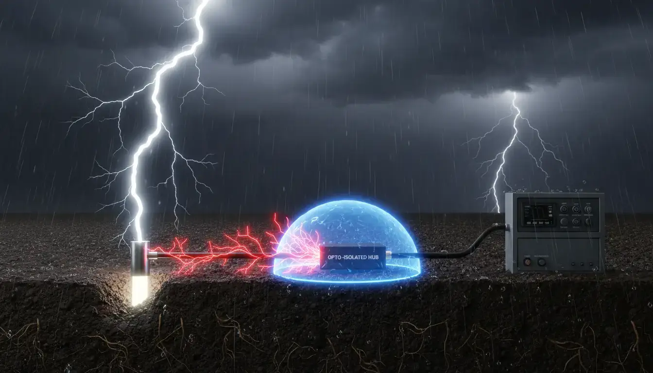
Figure 1: How a massive earth potential difference travels across the RS485 shield/ground, exceeding the transceiver’s common-mode limit and destroying the PLC port.
This sounds bulletproof in theory. But there is a fatal Achilles’ heel written deep into the official EIA-485 specification concerning the RS485 common mode voltage limit.
“A compliant EIA-485 receiver must operate correctly only when the common-mode voltage—the voltage difference between the local receiver ground and the remote transmitter ground—remains strictly between -7 Volts and +12 Volts. Exceeding this boundary will result in data corruption, and massive transients will result in catastrophic thermal failure of the transceiver junction.”
IEEE Standard for Electrical Characteristics of Generators and Receivers ANSI/TIA/EIA-485-A SpecificationIn a clean laboratory environment it is trivial to maintain the ground potential difference under 12 Volts. In a real wastewater treatment plant or a sprawling megawatt solar farm, it is practically impossible.
When you pull a 1,000-meter copper RS485 cable between a master PLC in Building A and a slave sensor array in Building B, you are physically bridging two entirely different earth ground potentials. If a lightning strike hits the soil 500 meters away, or a massive industrial VFD dumps high-frequency Pulse Width Modulation (PWM) switching noise into the local ground plane, the earth potential at Building B might violently spike to 150 Volts relative to Building A.
Because electrons always seek the path of least resistance to equalize, this massive 150-volt surge rushes across the RS485 shielding and signal wires. It hits the communication port of your master PLC, vastly exceeding the +12V design limit, and punches straight through the fragile silicon junction of the transceiver chip.
Interactive Ground Loop & VFD Noise Simulator
Adjust the sliders to simulate real-world environmental noise on an unprotected RS485 line. Watch what happens to the PLC’s internal voltage when the -7V to +12V common-mode limit is breached, and see how activating the Valtoris Optical Isolation barrier purifies the port.
How to Test for RS485 Ground Loops in the Field
Before you start ripping out cables or blaming your SCADA software, you must mathematically prove that a ground loop exists. You do not need expensive diagnostic gear to do this; a standard digital multimeter is enough.
- Step 1: Completely disconnect the RS485 cable (A+, B-, and Shield/GND) from the communication port of your Master PLC.
- Step 2: Set your multimeter to measure DC Voltage (and then test again in AC Voltage mode to catch high-frequency VFD induction).
- Step 3: Place the black probe on the Earth Ground terminal of your local PLC cabinet (Building A).
- Step 4: Place the red probe on the Shield wire or the GND wire coming from the remote field cable (Building B).
The Diagnosis: If your multimeter reads a floating voltage greater than 5V, or if the voltage is wildly fluctuating, you have just positively identified a destructive earth potential difference. Your network is a ticking time bomb. Reconnecting that cable without an optical isolator will eventually exceed the transceiver’s common-mode limit.
Teardown: Looking Inside an Industrial RS485 Optical Isolator
To get a real handle on how to permanently beat these destructive ground loops, we need to get under the hood of the electrical architecture. See the internal functional block diagram of a true industrial-grade isolated protocol gateway.
Technically Accurate 3-Way Isolation Architecture
Notice how data (Optocouplers) and power (DC-DC) perfectly bridge the physical creepage gap.
The very first thing an electrical engineer notices when inspecting a properly designed isolated board is a literal, physical gap in the fiberglass. This is known in the industry as the Isolation Barrier or Creepage Distance. You will see a distinct line—often physically milled out of the board—where absolutely no copper traces exist. This trench separates the “Safe Side” (where your expensive PLC or Ethernet switch connects) from the “Dangerous Side” (the field RS485 wires running out into the factory).
Scientifically, it is impossible for stray ground loop currents to flow from the field device to the master controller by physically breaking the continuous copper connection. But this immediately gives rise to a paradox: If the copper wires are completely severed, how does the Modbus data cross the chasm?
The Optical Barrier: How Optocouplers Block Destructive Surges
The magic happens inside the small, typically 8-pin Integrated Circuits (ICs) bridging the physical gap on the PCB. These are Optocouplers (or in newer designs, high-speed capacitive digital isolators). They perform a critical protective function known as RS485 Galvanic Isolation.
When the RS485 transceiver on the “dangerous side” receives a bit of data (a logical ‘1’ representing a high voltage state), it doesn’t send that raw voltage into the PLC. Instead, it sends a tiny, precisely calibrated amount of current to a microscopic Light Emitting Diode (LED) hidden entirely inside the optocoupler chip’s epoxy casing.
- Step 1: The internal LED flashes a tiny, high-speed pulse of infrared light.
- Step 2: The light passes through a transparent silicon barrier in the chip.
- Step 3: A highly sensitive phototransistor on the ‘safe’ side inside the chip’s cavity picks up that flash of light and converts it back into a clean, electrical logical ‘1’.
Because light is completely immune to electromagnetic interference, and because photons do not carry electrical charge, the Modbus data crosses the barrier effortlessly while the lethal voltage surge is left stranded.
| Environmental Risk Level | Recommended Isolation Level | Typical Application Scenarios |
|---|---|---|
| Low Risk (Indoor, Short Range) | Standard ESD Protection (e.g., Valtoris V Series) | Indoor factory floors, clean server rooms, HVAC controllers within the same building. Requires 9~24V DC. |
| Medium Risk (Building to Building) | 1500V Optocoupler Isolation | Inter-building communication, minor VFD presence, standard Modbus RTU metering. |
| High Risk (Heavy Industrial / Outdoor) | 3000V True Galvanic Isolation (e.g., Valtoris VI Series) | Solar inverter arrays, multi-megawatt motor cabinets, wastewater plants. Supports industrial wide-voltage inputs (e.g., 9~24V or 18~36V DC). |
The Dirty Secret of Cheap Isolators: Why 3-Way Isolation is Mandatory
If you search Amazon or industrial supply catalogs for “RS485 Isolator,” you will find generic, unbranded dongles selling for as little as $15. If you deploy these in a heavy industrial setting, your network will still eventually crash. Why? Because of the dirty secret of cheap isolation electronics: They only isolate the data lines, not the power supply.
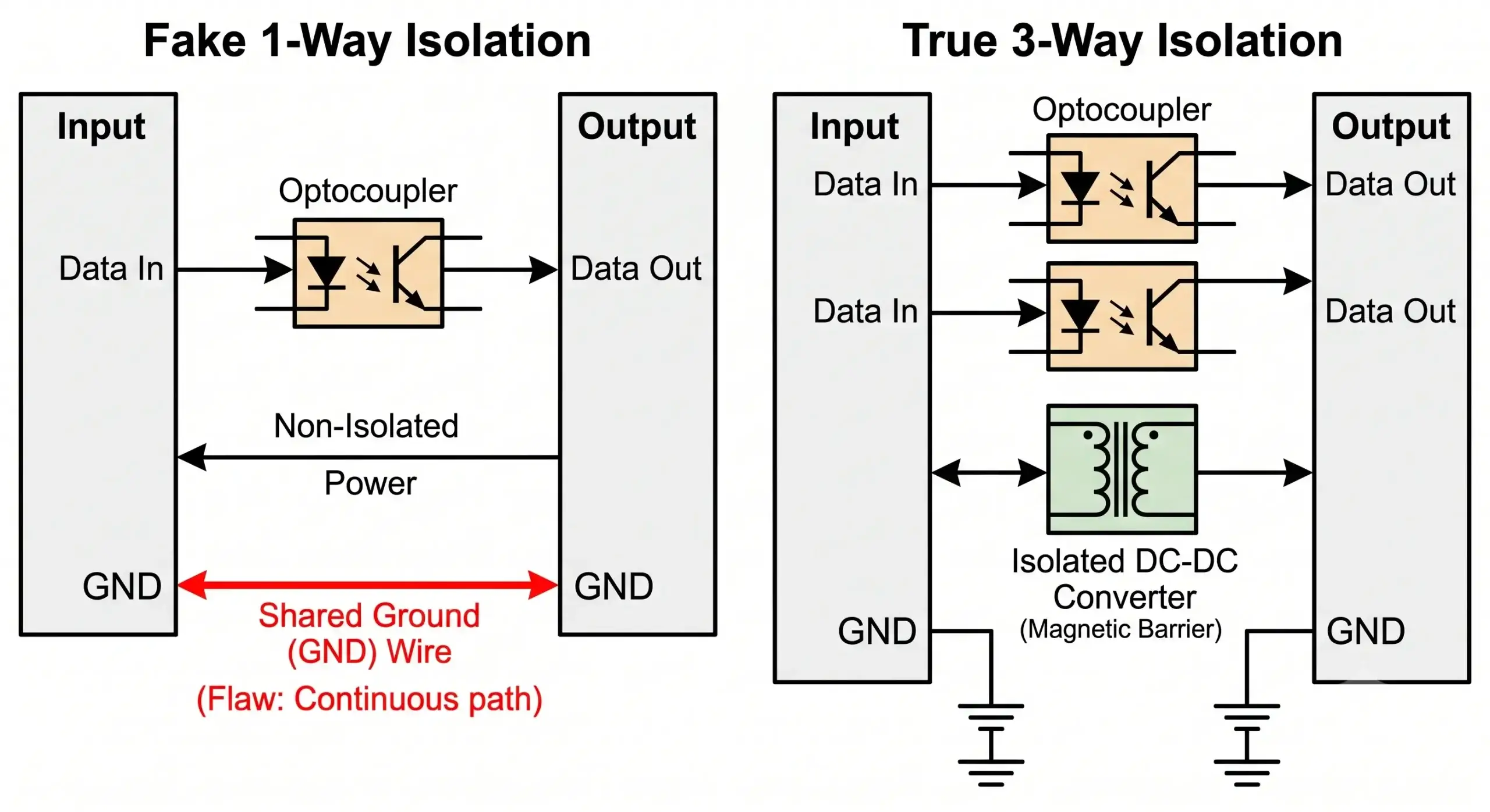
Figure 3: True 3-Way Isolation Architecture. Professional gateways completely isolate Input Data, Output Data, and the Power Supply, ensuring no ground loops can bypass the optical barrier.
In order for the transceiver chip on the “dangerous side” of the isolation barrier to function and read the field wires, it needs an active 5V DC power source. Cheap isolators cut corners to save money by simply drawing this power from the PLC side, running a continuous copper VCC and GND trace right across the isolation barrier to power the chip.
This entirely defeats the purpose of the optocouplers. The 200V surge will simply ignore the optical chips, travel straight down the shared ground line, bypass the barrier entirely, and fry your equipment.
| Design Architecture Feature | Cheap Commercial Isolator ($15) | Industrial 3-Way Isolated Gateway |
|---|---|---|
| Signal Transfer Mechanism | Low-speed Optocouplers (Causes baud rate latency & CRC errors) | High-speed Opto/Digital Isolators (<100ns propagation delay) |
| Power Supply Architecture | Shared Ground Plane (Fatal design flaw, surge path remains) | Isolated DC-DC Magnetic Transformer (Total ground separation) |
| Surge Withstand Rating | Typically 500V (Minimal ESD protection only) | 1500V to 3000V True Galvanic Isolation |
| Protocol Handling | Dumb transparent passthrough (Blind forwarding of collisions) | Intelligent Modbus Caching & Ethernet Protocol Conversion |
Professional engineering standards mandate 3-Way Isolation (Isolating the Power Supply, Input Data, and Output Data). This requires a dedicated Isolated DC-DC Converter module. This part employs small magnetic induction coils to transfer power over the isolation barrier without direct wire contact, so the ground planes are 100% segregated. This is precisely why true industrial isolated gateways utilize specialized wide-voltage inputs (e.g., 9~24V or 18~36V DC) to feed the primary side of the magnetic transformer.
Beyond Isolation: TVS Diodes and Shielding for Ultimate Reliability
While an optical barrier is the ultimate defense against sustained ground loop currents, a robust industrial design requires a multi-layered, defense-in-depth strategy to handle incredibly fast transient spikes (like nearby lightning strikes, electrostatic shock, or heavy relay switching).
If you look closely at the green screw terminal blocks on our PCB teardown, you will see robust, barrel-shaped components soldered in parallel across the A+ and B- lines right where the field wires enter the board. These are Transient Voltage Suppressor (TVS) Diodes (often from the SMAJ or SMBJ semiconductor series).
“A TVS diode is placed across the RS-485 bus lines to protect the bus from high voltage transients. During an overvoltage event, the TVS diode enters avalanche breakdown within picoseconds, clamping the voltage to a safe level and shunting the massive surge current directly to earth ground before it can damage the transceiver.”
Texas Instruments Application Report SLLA292A: RS-485 Interface Circuit ProtectionThe TVS diode is an ultrafast pressure relief valve when an electrostatic discharge (ESD) event hits the line. It clamps the voltage spike to a safe value, say 7V, and dissipates the kinetic energy. But the problem is, it’s not so simple to design: The TVS diodes inherently have parasitic capacitance. An inexperienced engineer will use the wrong diode and the capacitance will round off the sharp edges of the RS485 square waves and effectively destroy high speed (115.2 kbps) communication. Good industrial designers combine high clamping power with ultra low capacitance parts for safety and sharp signal integrity.
The Latency Cost: Do Optical Isolators Slow Down Your Baud Rate?
A common objection from control engineers is performance degradation. “If I convert electrical signals into light and back into electricity, won’t that introduce massive latency and cause Modbus RTU timeout errors?”
The answer depends entirely on the component quality. Cheap isolators use legacy phototransistors with slow rise and fall times. When you push a high-speed 115200 bps signal through them, the slow optical switching rounds off the sharp edges of the square waves, causing the receiving PLC to misread the bits (framing errors).
Industrial grade isolators however solve this problem by using high speed digital capacitive isolators or ultra fast optocouplers (like the 6N137 logic gate optocouplers). These components feature a propagation delay of less than 50 nanoseconds (ns). To put that in perspective, at a standard baud rate of 19200 bps, transmitting a single bit takes about 52,000 nanoseconds. The sub-50ns delay introduced by the optical barrier is mathematically invisible to your PLC and will absolutely not trigger any Modbus polling timeouts.
Wiring the Shield: How to Ground an Isolated RS485 Segment
Even if you purchase a premium 3000V isolated gateway, you can completely ruin the isolation barrier during installation by miswiring the cable shield. The most common mistake engineers make is treating the isolated gateway like a regular terminal block and bridging the shields together.
If you connect the incoming cable shield from the field to the output shield of the PLC side, you have just created a physical copper bypass around the optical isolators. The high-voltage ground loop will travel straight down the shield, bypass the optocouplers, and hit your PLC.
The Golden Rule of Isolated Shield Wiring:
Ground the cable shield at one end only. Typically, you should terminate the long field cable’s shield to Earth Ground at the local isolated gateway cabinet. Ensure that the shield on the “Safe Side” (between the isolator and the PLC) is grounded locally, but never let the two shields touch. The galvanic barrier must physically separate the ground planes.
The Architectural Conclusion: Buy vs. Build
A deep understanding of galvanic isolation, optoelectronics and common mode rejection will give you a real leg up on troubleshooting unstable SCADA networks. If your Modbus polling intermittently drops out when heavy machinery powers up, or you’re swapping out burnt communication modules every summer during thunderstorm season, you now know exactly what is happening at the electron level.
You could attempt to mitigate this by stringing together aftermarket optical repeaters, designing custom DC-DC isolation boards, and soldering custom TVS diode arrays in your lab. However, in modern IT/OT convergence projects, relying on fragile, pieced-together serial daisy-chains is a massive architectural liability that increases maintenance overhead and downtime risks.
The way you implement this hardware fix is entirely dependent on your current network topology. If you just want to protect an existing legacy SCADA system and don’t want to change your software or wiring architecture, then a drop-in Isolated RS485 Hub is the easiest solution. However, if you are actively modernizing the plant floor and want to push field data directly to the local area network (LAN) and simultaneously create a 3000V galvanic barrier, then upgrading to an Isolated RS485-to-Ethernet Gateway is the better architectural choice.
Implement the Fix: True 3-Way Isolation
Stop troubleshooting fried PLCs. Deploy pre-engineered hardware with native 3000V optical isolation to permanently sever destructive ground loops. Choose the right module for your network:
Frequently Asked Questions: RS485 Isolation & Ground Loops
Can grounding the RS485 shield on one end replace the need for an optical isolator?
No. Shields of cables are great at blocking airborne electromagnetic interference (EMI) and radio frequency noise when they are grounded at a single point. However, large earth potential differences can result in common-mode voltage surges that the shield cannot prevent. If a lightning strike shifts the ground potential at the slave node by 100V, that voltage will still travel down the A/B signal wires to your PLC. Only galvanic isolation (severing the copper connection entirely) can stop these surges.
Do I need to install an RS485 isolator at every single slave device on the daisy-chain?
In most standard industrial applications, placing a single industrial optical isolator at the Master Node (the PLC or SCADA gateway) is sufficient to break the main ground loop. However, for outdoor installations with high lightning risks, isolating individual segments may be necessary.
What is the difference between optical isolation and magnetic digital isolation for RS485?
Optical isolation transmits data via light (LEDs), while digital isolators use micro-transformers (magnetic coupling). While magnetic isolators are faster, optical isolation is 100% immune to extreme external magnetic fields, making it the gold standard near massive VFDs and induction furnaces.
I installed an isolator, but my SCADA system is still reporting Modbus timeout errors. What else could be wrong?
If the physical layer is clean, the timeouts are likely at the protocol layer. Common causes include missing 120-ohm termination resistors, mismatched baud rates, or polling frequencies that are too fast for the slave devices. You will need to optimize your Modbus Master software settings.
