
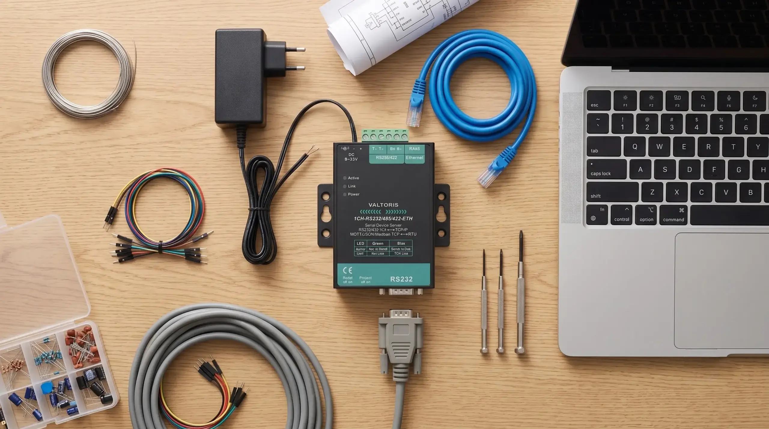
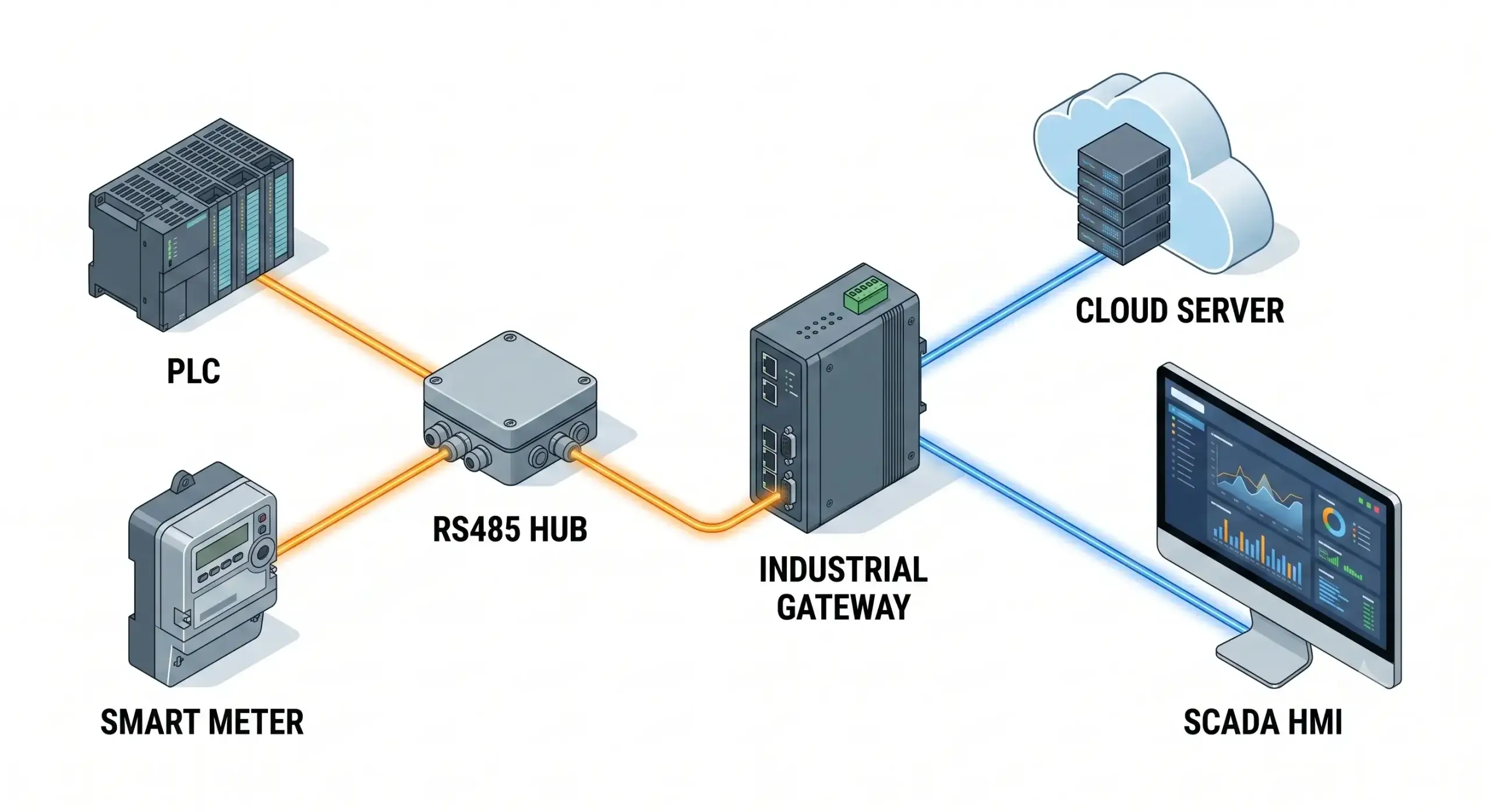
One of the biggest challenges for industrial automation engineers is integrating legacy serial systems with modern network infrastructure. You have reliable RS232 machinery (CNCs, scales) and RS485 sensor networks that cannot natively talk to your modern cloud dashboards or Ethernet SCADA systems.
This comprehensive guide fills the void. You will learn how to overcome serial distance limitations, and how to bring your legacy assets onto your IP network – without replacing expensive hardware or rewriting legacy software.
📋 What You’ll Learn in This Guide:
- The 8-Step Configuration: Moving from bare-wire connections to static IP assignment.
- Wiring Pinouts: Eliminating the most common mistakes for RS232, RS485, and RS422.
- Software Integration: Socket programming, Virtual COM Ports, and Hardware Modbus Gateways.
Connecting Legacy Serial Devices to Modern IP Networks
RS232 is a point-to-point relic that degrades quickly, limiting reliable transmission to just 15 meters. RS485 pushes this to 1200 meters, but remains a localized, half-duplex bus.
To understand how do serial to ethernet converters work to shatter these physical boundaries, you must look at the protocol stack. By using an Industrial Serial to Ethernet Converter, the device actively performs protocol handshakes, buffers raw serial data, and packages it into structured TCP/IP payloads. So you can read equipment data from a control room hundreds of meters away or even from the other side of the world.
Pre-Configuration Checklist
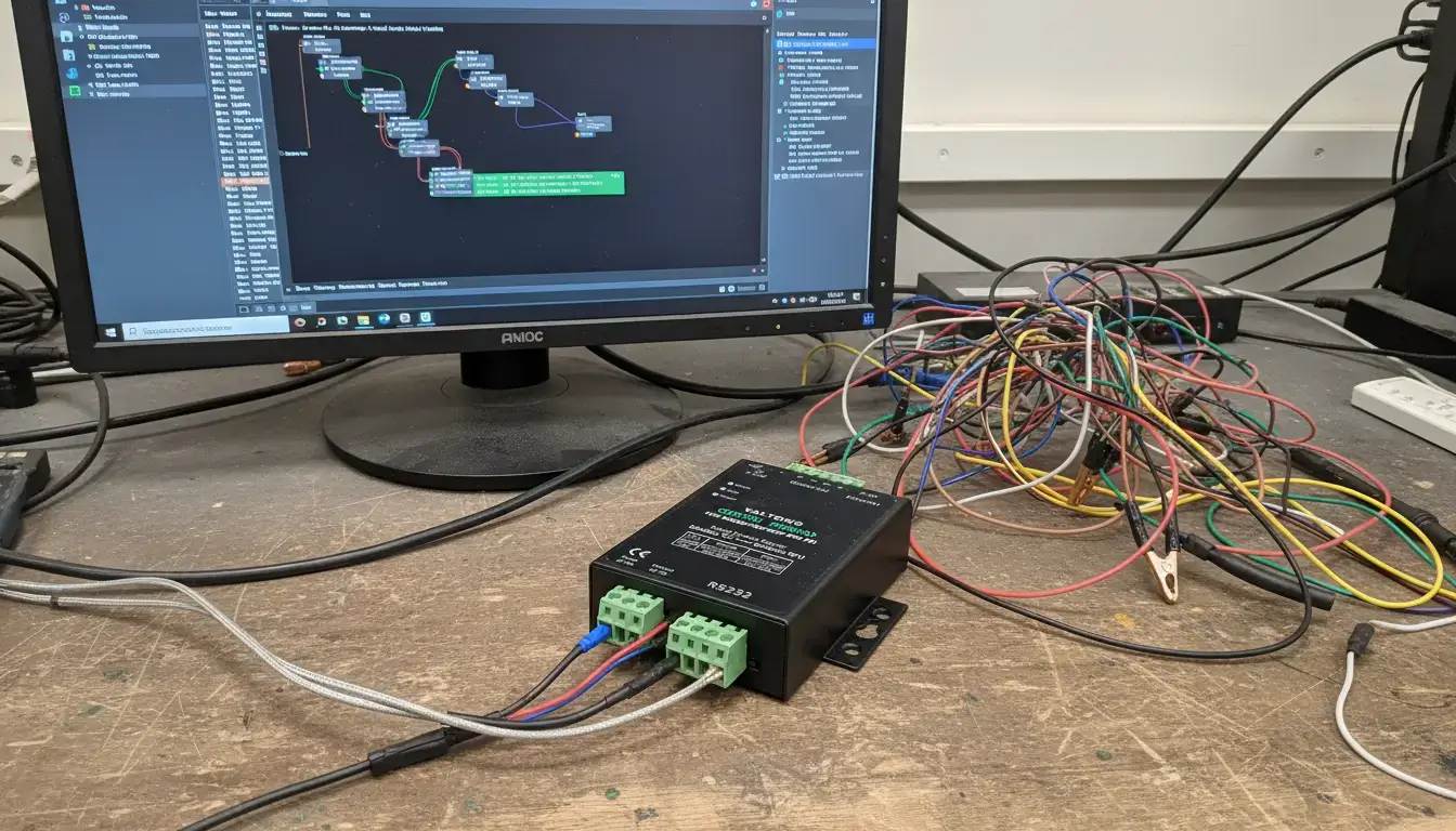
The converter cannot “guess” your machine’s language. Check off these items once you have verified them in your end-device’s manual.
Architecture Decision: Software, Hardware, or Both?
Before wiring anything, you must determine your integration architecture. If you’re trying to get data from a serial device onto a network, the solution isn’t always purely hardware or purely software.
- Software Only (Port Sharing): Valid only if both your end-device and your SCADA system are physically connected to computers. One PC shares its physical COM port over the LAN.
- Hardware Only (TCP Direct): Your remote device connects to a physical hardware converter. Your central SCADA system natively supports TCP/IP and connects directly to the converter’s IP address.
- The Hybrid Approach (Hardware + VCOM): Required when your device is remote, but your central SCADA software is extremely old and only recognizes physical
COM1orCOM2ports. You use a hardware converter in the field, and Virtual COM software on your PC.
Step 1: Serial Wiring (RS232, RS485, RS422)
Need to make your own cable? If you are wondering how to convert RS232 to Ethernet, proper physical wiring is your first critical step. Since modern industrial gateways are 3-in-1 devices, use the interactive matrix below to select your specific protocol (RS232, RS485, or RS422) and verify the terminal logic before applying power.
Interactive Serial Pinout & Termination Quick-Reference Matrix
| Converter Pin (DTE) | End-Device Pin (DTE) | Function |
|---|---|---|
| Pin 2 (RXD) | Pin 3 (TXD) | Receive Data |
| Pin 3 (TXD) | Pin 2 (RXD) | Transmit Data |
| Pin 5 (GND) | Pin 5 (GND) | Signal Ground (Mandatory) |
Pin 2 (RXD) <=========+========> Pin 3 (TXD)
Pin 3 (TXD) <=========+========> Pin 2 (RXD)
Pin 5 (GND) <==================> Pin 5 (GND)
Step 2 & 3: Power and Network Link
Plug the Ethernet cable into the converter and connect it to your switch. Provide regulated power (industrial standard is 9-24V DC). The network LED should indicate an active link status.
Step 4: Find the Converter’s IP Address
If your converter uses DHCP or has a static default IP (like 192.168.1.254) that doesn’t match your computer’s subnet, a web browser will not be able to reach it. To successfully convert serial port to Ethernet networks, establishing initial IP communication is mandatory.
Can’t find the device IP?
If you are on a different subnet, use the Valtoris Discovery Tool (VirCom). It forces a UDP broadcast to locate serial servers on the physical MAC layer, regardless of IP mismatches.
Download VirCom Discovery Tool ↓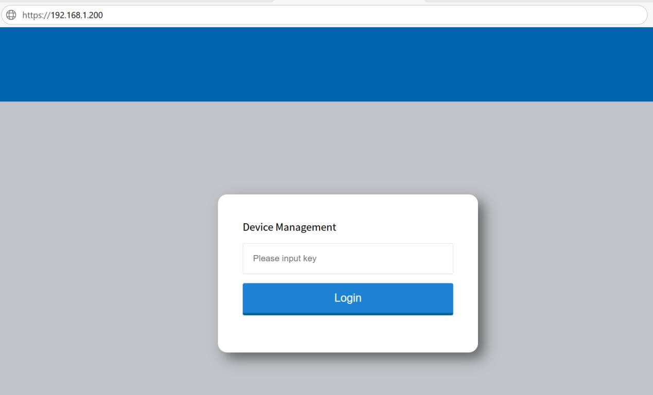
Step 5 & 6: Network and Serial Parameters
Access the web GUI and set a Static IP. If your converter pulls a new IP address via DHCP after a router reboot, your SCADA software will permanently lose communication.
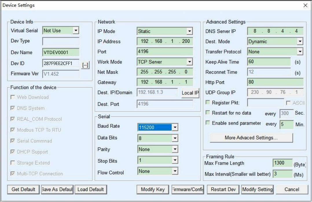
| Setting | Best Practice | Reasoning |
|---|---|---|
| IP Address Mode | Static | Prevents connection drops caused by DHCP expiration. |
| Subnet Mask | 255.255.255.0 | Standard for typical Class C local networks. |
| Gateway | Your Router’s IP | Essential only if accessing from a different subnet. |
Next, navigate to the serial port settings tab. Input the exact Baud Rate, Data Bits, Parity, and Stop Bits you verified in your checklist.
| Parameter | Common Industrial Values | Impact if Incorrect |
|---|---|---|
| Baud Rate | 9600, 19200, 115200 | Total failure or severe data corruption (garbage characters). |
| Data Bits & Parity | 8 bits, None (8-N-1) | Framing errors; device rejects the packets. |
| Flow Control | None, Hardware (RTS/CTS), or Software (XON/XOFF) | Transmission halts waiting for signals that don’t exist. |
Step 7: Choose Operating Mode (TCP/UDP)
You must explicitly define how the converter behaves on the network:
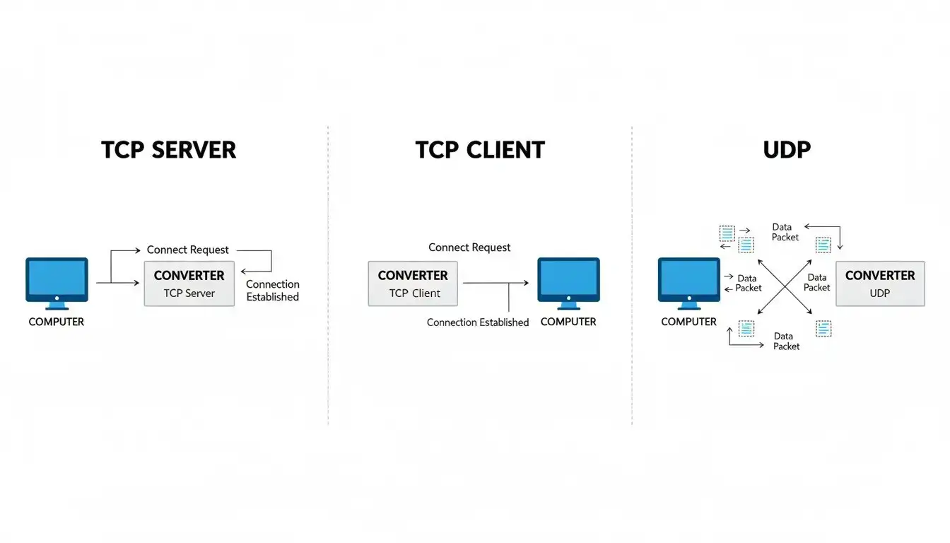
| Mode | Initiation | Typical Use Case |
|---|---|---|
| TCP Server | Waits for incoming connections. | Central SCADA or VCOM driver actively polling the device. |
| TCP Client | Actively connects to a remote server. | Converter pushing sensor data to a centralized cloud server IP. |
| UDP Mode | Connectionless transmission. | Fast, local broadcasting where packet loss isn’t critical. |
For most polling applications, TCP Server is the preferred method. Select this mode, assign a local port (e.g., 4001, or 502 for Modbus), and save the settings.
Step 7.5: Validate the Connection (Before SCADA Integration)
Before connecting your heavy SCADA system, verify the raw IP link. Open your Windows Command Prompt or Linux terminal:
Reply from 192.168.1.100: bytes=32 time=2ms TTL=64
// If ping is successful, test the specific port using Telnet or Netcat:
C:\Users\Admin> telnet 192.168.1.100 4001
If the Telnet window opens to a blank black screen without connection errors, your serial-to-Ethernet tunnel is successfully established and ready for software integration.
Step 8: Software Integration Options
How does your computer actually talk to the network port? Choose based on your architecture:
Option A: Socket Programming (For Custom Software)
If you are writing custom data acquisition scripts, simply open a TCP socket to the converter’s IP and port. This works natively in Python, C#, Java, etc.
s = socket.socket(socket.AF_INET, socket.SOCK_STREAM)
s.connect((‘192.168.1.100’, 4001))
s.send(b’\x01\x03\x00\x00\x00\x01′) # Example Modbus query
response = s.recv(100)
print(response)
Option B: Virtual COM Port (For Legacy RS232 CNCs)
Many legacy programs only recognize physical ports like COM1. By installing specialized serial to ethernet converter software (such as a VCOM driver), you can simulate a hardware port in Windows, intercepting TCP/IP network data and feeding it to your software as if a physical RS232 cable were attached.
Option C: Hardware Modbus Gateway (For RS232 PLCs/Controllers)
While RS485 is common for multi-node sensor networks, but many older PLCs and terminal controllers still use RS232 for point-to-point Modbus RTU communication. If you are integrating these RS232 devices into a modern SCADA system, you will often get timeout errors when using VCOM drivers because of Windows network jitter. In Modbus Gateway Mode the converter is a hardware translator for two languages. It listens on port 502 for Modbus TCP requests, times the conversion to Modbus RTU exactly, and talks perfectly with your RS232 gear.
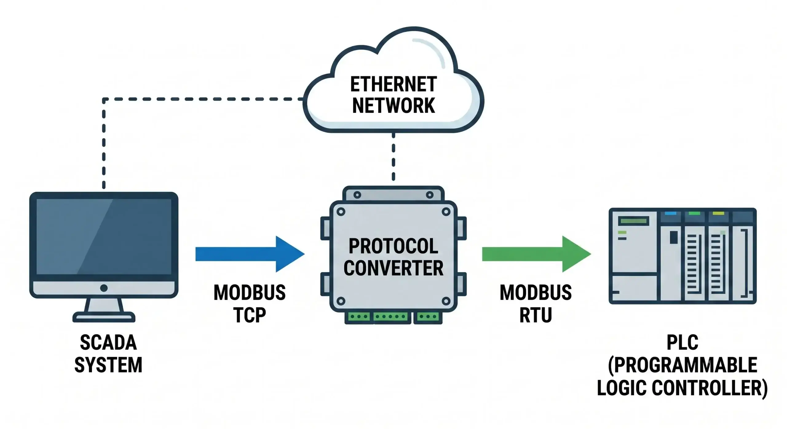
The Engineering Perspective: Reliance on VCOM software to translate protocol introduces unnecessary latency and potential points of failure. For reliable SCADA polling, it is best practice to do this translation at the hardware level.
Tired of Dropped RS232 Connections & VCOM Crashes?
If your legacy machinery (like CNCs or scales) is losing data due to unstable Virtual COM drivers or latency from cheap commercial adapters, it’s time for an upgrade. Our industrial device servers feature robust hardware buffers and rock-solid TCP/IP stacks for zero-packet-loss transparent transmission.
Troubleshooting the Physical Layer
| Symptom | Probable Cause | Action Required |
|---|---|---|
| Can’t Ping Converter | Subnet Mismatch | Verify PC IPv4 settings match the converter’s subnet. |
| Ping OK, TCP Fails | Port Blocked | Ensure the specified port (e.g., 4001) is open in local firewalls. |
| TCP Connects, No Data | A/B Polarity Reversed | Swap the TX and RX pins (Pin 2 and 3) on the RS232 connection. Using a straight-through cable instead of a null-modem crossover is the #1 cause of this error. |
| Garbled Data Returned | Baud/Parity Mismatch | Re-verify the end-device’s exact serial parameters. |
Real-World Application & ROI
Scenario: A manufacturing facility needed to integrate a legacy CNC machine (which only had a physical RS232 COM port) into their modern Ethernet-based MES (Manufacturing Execution System) located 300 meters away.
- Wired a Null-Modem RS232 cable (crossing TX and RX) from the CNC to the converter and applied industrial 24V power.
- Used the discovery tool to locate the converter IP.
- Set a Static IP, configured the RS232 port to 9600/8/N/1, and set the mode to TCP Server.
- Installed Virtual COM (VCOM) software on the central PC, mapping the converter’s IP to a virtual “COM3”.
Result: Total configuration time was 20 minutes. The facility bypassed trenching new serial cables, resulting in an estimated $8,000 in installation savings.
Industrial Considerations: What to Look For
Standard consumer IT gear fails rapidly in harsh environments due to extreme temperatures and electrical noise. For mission-critical deployments, ensure your converter meets these baseline specs:
| Feature | Industrial Standard | Why It Matters |
|---|---|---|
| Temperature | -40°C to 85°C | Control panels experience severe thermal cycling. |
| Power Input | 9-24V DC | Avoids fragile 5V USB connections; standardizes with panel power. |
| Isolation | 1.5KV or higher | Opto-isolation prevents lethal ground loops from frying network switches. |
| MTBF | > 100,000 hours | Industrial units significantly outlast the 50k hour lifespan of commercial gear. |
Frequently Asked Questions
Will converting serial to Ethernet introduce latency that breaks my legacy software?
Can I access my converter from outside my local network over the internet?
Do I need a separate power line for the converter?
How do I fix “Modbus Polling Timeout” errors after upgrading to Ethernet?
Still Getting “Timeout” Errors? Stop Guessing.
If you have done all the steps and your legacy software still won’t communicate, your adapter most likely does not have the hardware buffer or Modbus translation capabilities to handle strict timing protocols. Let us know what equipment you are connecting and our engineers will recommend the appropriate industrial gateway architecture.
