
🔍 Technical Review & Standards Reviewed by the Valtoris Industrial Networking Team. > The wiring diagrams provided in this guide strictly adhere to EIA/TIA-232-F serial communication standards and TIA/EIA-568-B Ethernet cabling specifications to ensure safe signal transmission.
If you looked up “rs232 to ethernet cable pinout” you are probably thinking of two things.
- You have a device with an RS232 port that uses an RJ45 connector (common on industrial PLCs, network gear, and access control systems). You need to connect it to your computer’s DB9 serial port.
- You want to use cheap Ethernet cable to extend an RS232 connection beyond the standard 15-meter limit, because official RS232 cables are expensive.
Either way you need to know which wire goes where.
Lets be clear: RS232 and Ethernet are different. You can’t plug an RS232 device into an Ethernet port. Don’t expect it to work just by plugging it in. However, you can use the internal wires of an Ethernet cable to carry RS232 signals. The trick is getting the RS232 to ethernet pinout right.
⚠️ Crucial Note Before You Wire: A DIY RS232-to-RJ45 cable is a passive connection. It simply uses Ethernet wires to carry serial signals up to 15 meters. It will NOT put your RS232 device onto your local IP network (LAN). > If you need to access your serial device via an IP address, or want to connect it to an Ethernet switch, a passive cable will fail (and may burn your board if plugged into PoE). True network access requires an active conversion architecture to encapsulate serial payloads into TCP/IP packets.
Here’s a fact that might surprise you: RS232 is still used in a massive portion of industrial equipment—PLCs, scales, CNC machines, medical devices, and test equipment. It’s been around since 1969, and it’s not going away anytime soon.
But here’s the frustrating part: The majority of communication failures in serial networks come from simple wiring errors and grounding mistakes. If you’ve ever connected everything “correctly” and gotten nothing but garbage data or dead silence, you’re not alone. This guide covers not just what connects where, but why it works that way, and—most importantly—what to check when it doesn’t.
- The “TX/RX Cross” Mystery: Null Modem vs. Straight-Through
- Core Connector Pinouts: DB9 and RJ45
- DB9 Connectors (The Traditional Standard)
- RJ45 Pinout (T568B Standard)
- Three Common Industrial Scenarios
- Scenario 1: DB9 to RJ45 (The Console Standard)
- Scenario 2: Terminal Blocks
- Scenario 3: Using Ethernet Cable as RS232 Extension
- What About Flow Control (RTS/CTS)?
- The $5,000 Grounding Mistake
- Systematic Troubleshooting: The Loopback Test
- Decision Flowchart: When It Doesn’t Work
- Frequently Asked Questions
The “TX/RX Cross” Mystery: Null Modem vs. Straight-Through
The most common reason for a “silent” connection is getting the TX and RX lines backward.
Three wires are all you need for basic communication:
| Signal | Purpose |
|---|---|
| TX (Transmit) | Sends data out |
| RX (Receive) | Receives data in |
| GND (Ground) | Reference for both signals |
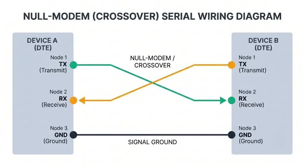
The Rule: TX on one end connects to RX on the other. Data needs a path, and ground gives it a reference. Why cross them? Because one device’s “transmit” must go to the other device’s “receive.” If you connect TX to TX, nothing happens—they are both trying to talk, and nobody is listening.
Identifying Your Device: DTE vs. DCE
To get the wiring right, you must identify your device type:
- DTE (Data Terminal Equipment): Like your PC or a PLC.
- DCE (Data Communication Equipment): Like a modem or some Ethernet converters.
When to cross: If you connect two DTE devices (like a PC to a PLC), you must use a crossover connection to swap pins 2 and 3. Understanding the exact null modem cable pinout is essential to keep these TX/RX roles separate and avoid communication silence.
⚠️ Stuck on RX/TX Swap? Check your Frame with our Modbus CRC Calculator
Core Connector Pinouts: DB9 and RJ45
DB9 Connectors (The Traditional Standard)
Most RS232 devices use a DB9 connector. DB9 pins are numbered, and for standard communication, you only care about three:
| Pin | Signal |
|---|---|
| 2 | RX |
| 3 | TX |
| 5 | GND |
If both ends are DB9: You need a null-modem cable that crosses pins 2 and 3.
- Converter pin 3 → Device pin 2
- Converter pin 2 → Device pin 3
- Pin 5 → Pin 5
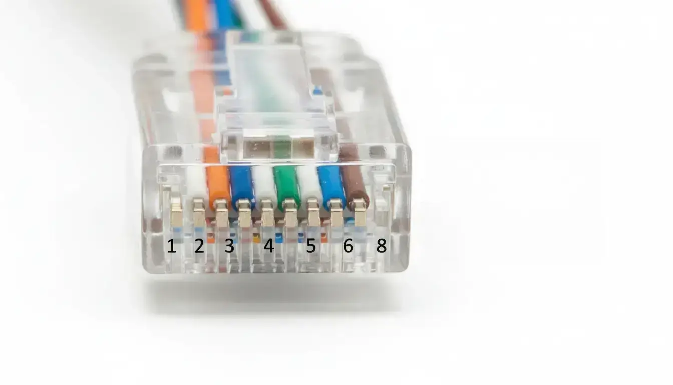
RJ45 Pinout (T568B Standard)
🛑 Crucial Disclaimer: There is no standard for RS232 over RJ45 connectors. We use the standard EIA/TIA-561 mapping below but manufacturers (Cisco, Allen-Bradley, Moxa) often do proprietary pinouts. Always consult your specific device’s datasheet before wiring.
Ethernet cable uses 8 wires with standard colors. The T568B wiring is most common:
RJ45 Pinout (T568B Standard)
For RS232, we only need a few of these wires. You can assign colors yourself—just write down what you used.
RS232 (DB9) to RJ45 Pinout Visualizer
Select an industrial preset or configure custom mapping to generate your wiring diagram.
*Standard EIA-561 mapping. Handshake pins omitted for 3-wire operational clarity unless flow control is enabled.
CRITICAL BURN HAZARD
This is a passive pinout. NEVER plug this RJ45 end into an active PoE switch. 48V PoE power will instantly bypass the DB9 shell and fry your PLC/device motherboard.
15-Meter Distance Limit
Passive cables longer than 50ft will suffer severe packet drop and ground loop interference.
Three Common Industrial Scenarios
Scenario 1: DB9 to RJ45 (The Console Standard)
Many devices, such as PLCs, door controllers, and network switches, use RJ45 jacks for their serial ports. To connect these to your computer, you need a cable going from the RJ45 port on the device to the DB9 port on your computer.
Standard RJ45 to DB9 Wiring Diagram & Pinout:
(Note: While RJ45 serial pinouts vary by manufacturer, the following uses the common EIA/TIA-561 standard mapping.)
| RJ45 Pin | DB9 Pin | Signal |
|---|---|---|
| 1 | 2 | RX |
| 2 | 3 | TX |
| 3 | 5 | GND |
| 4-8 | – | Not connected |
This wiring follows the standard DTE (Data Terminal Equipment) configuration, which is the case for almost all modern computers.
STANDARD CONSOLE CABLE WIRING
EIA/TIA-561 Mapping (DB9 Female to RJ45)
If your device is DCE (Modems or specific converters):
| RJ45 Pin | DB9 Pin | Signal |
|---|---|---|
| 1 | 3 | TX |
| 2 | 2 | RX |
| 3 | 5 | GND |
Always check the manual of your specific equipment. Manufacturers like Cisco, Digi, and Siemens often have their own pinout standards.
Scenario 2: Terminal Blocks
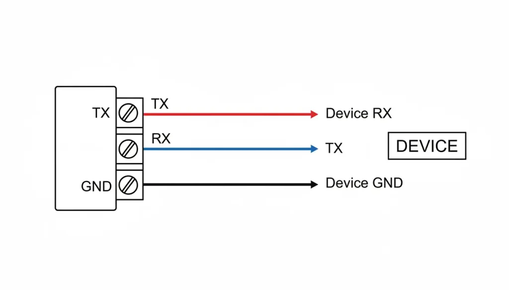
Common in industrial converters, these feature three screws labeled TX, RX, and GND:
| Terminal | Connect To |
|---|---|
| TX | Device’s RX |
| RX | Device’s TX |
| GND | Device’s GND |
Scenario 3: Using Ethernet Cable as RS232 Extension
The RS232 standard technically limits communication to 15 meters (roughly 50 feet). Beyond that, signal degradation and noise become significant issues. When running RS232 over Cat5 (or Cat5e/Cat6) cables, the twisted pairs act as an excellent extension option to help negate electromagnetic interference.
For Longer Runs: If you must go further using Cat5 or Cat6, you need to lower the baud rate (e.g., from 115200 to 9600) to compensate for signal loss and capacitance.
💡 Pro Tip for Distances Over 15m: Extending RS232 passively over long Cat5e runs introduces severe voltage drops and electromagnetic interference (EMI). In these scenarios, standard practice shifts from physical wiring extension to network encapsulation. By moving the RS232 signal onto the LAN at the edge, distance-based voltage drop is completely eliminated.
If both ends are DTE (computer to computer, or computer to most equipment):
| RJ45 End A | RJ45 End B | Signal |
|---|---|---|
| 1 | 2 | TX → RX |
| 2 | 1 | RX → TX |
| 3 | 3 | GND → GND |
| All others | Not connected | – |
This is a null modem crossover cable. TX on one end goes to RX on the other.
RJ45 NULL MODEM CROSSOVER CABLE
For extending RS232 over Cat5e (DTE to DTE Configuration)
If one end is DTE and the other is DCE (rare):
| RJ45 End A | RJ45 End B | Signal |
|---|---|---|
| 1 | 1 | TX → TX |
| 2 | 2 | RX → RX |
| 3 | 3 | GND → GND |
Professional Tip: To maximize the anti-interference benefits of Cat5/6 cable, never put TX and RX on the same twisted pair. Instead, pair TX with a Ground wire and RX with another Ground wire. This gives the signal better protection and it is more stable when it has to travel a long way which is really important in noisy industrial environments.
What About Flow Control (RTS/CTS)?
The setups above use only three wires, which is sufficient for most applications as many devices don’t require hardware flow control. However, if your device requires RTS/CTS:
| Signal | RJ45 Pin | DB9 Pin |
|---|---|---|
| RTS | 4 | 7 |
| CTS | 5 | 8 |
Use the same color scheme throughout and document it. You’ll thank yourself later when troubleshooting.
The $5,000 Grounding Mistake
You have to connect ground every time. Without it, the signals have no reference. Data will be garbled or completely missing. But here’s the nuance: shield ground is not the same as signal ground.
- Signal ground (pin 5 on DB9) carries the reference voltage for the data. It must be connected.
- Connecting the shield at both ends creates ground loops—current flows through the shield, inducing noise on your data lines. This is a common but costly mistake.
A $5,000 Lesson: A factory once put in a long RS232 cable that was connected to the ground at both ends. Every time a nearby machine started, the computer screen would flicker and crash. They lost over five thousand dollars in downtime while trying to find the error. When they removed the ground from one end of the RS232 cable the problem with the RS232 cable went away.
PROPER SHIELD GROUNDING
Eliminating Ground Loops in Industrial Environments
Systematic Troubleshooting: The Loopback Test
When your wiring seems okay but nothing is working, do not guess. Test it. The Loopback Test is a way to isolate the problem on your own without special tools.
- Disconnect the cable at the device end.
- Jumper TX to RX: Use a small wire to connect the Transmit pin to the Receive pin on the connector.
- Send Data: Use a terminal program (like Putty). If what you type appears on the screen, your converter and cable are perfect. If not, the link is broken.
Decision Flowchart: When It Doesn’t Work
SERIAL COMMUNICATION TROUBLESHOOTING
Follow this workflow to isolate wiring vs. configuration problems.
- Step 1: Verify Continuity Use a multimeter to confirm that TX on one end connects to RX on the other (not to itself), RX connects to TX, and GND connects to GND.
- Step 2: Check Power Confirm both the converter and the end device are powered. If they are not, nothing works.
- Step 3: Verify Serial Settings Baud rate, parity, data bits, and stop bits must match perfectly. A common mistake is a device at 9600 baud while the converter is at 19200.
- Step 4: Check Software & Addresses If using Modbus, is the device ID correct? Ensure your software points to the correct COM port or IP address.
- Step 5: Local Loopback Perform a loopback test directly on the device ports. If the device cannot read its own transmission, the problem lies within the device hardware, not the cable.
| Symptom | Likely Cause | Fix |
|---|---|---|
| No data | TX/RX swapped | Swap pins 1 and 2 |
| Garbled data | Wrong baud rate, or ground missing | Check settings, verify GND connected |
| Intermittent connection | Bad crimp or solder | Re-do the connector |
| Nothing works | Using Ethernet switch in between | You cannot put RS232 through a switch. It’s point-to-point only. |
A Note on Voltages and Isolation
One important note before you connect your custom cable: Standard RS232 signals swing between +12V and -12V. If your receiving end expects 0-5V TTL (like many microcontrollers), or if someone accidentally patches this RJ45 into an active PoE port (48V), hardware damage is almost guaranteed.
When to Move Beyond Passive Cables
Passive DIY cables are great for local, temporary troubleshooting. But for permanent factory floor deployments, the industry standard has shifted away from running long serial lines. The risks of ground loops (like the $5,000 mistake mentioned earlier) and EMI noise are just too high.
Instead, the reliable approach is to use Active Serial Servers at the edge. This provides optical/magnetic isolation to protect the PLC motherboards, and encapsulates the serial data into TCP/IP packets so it can route safely across your existing Ethernet LAN.
If your project requires true network encapsulation rather than physical wiring extensions, you will need to actively route your data. Read our step-by-step technical guide on how to convert RS232 to Ethernet using active gateways to learn about TCP/UDP modes and Virtual COM setups.
Frequently Asked Questions
Will plugging my DIY RS232-to-RJ45 cable into a PoE switch damage my equipment?
⚠️ Overvoltage Warning: If you plug your serial device into a live PoE port by mistake, the 48V surge will instantly bypass the transceiver and destroy the equipment’s motherboard. Always label your serial-over-Cat5 ports clearly.
Can I use a standard “Cisco Console Cable” (light blue) for any industrial RJ45 serial port?
How can I safely verify my custom RJ45 to DB9 cable works before connecting my PLC?
My cable passes the continuity test, but data becomes garbled when factory motors turn on. Why?
I extended RS232 over the network, but legacy CNC software only accepts COM1/COM2. How do I input an IP?
My physical wiring to the serial server is perfect, but my SCADA system still cannot read the sensor data.
🛡️ Why Valtoris Shares This Pinout Guide
“We manufacture industrial serial servers and LTE routers. But we know that right now, you probably just need the correct pinout to get a legacy machine back online. Use these diagrams to solve your immediate wiring problem. When your system eventually outgrows passive cables and requires active TCP/IP routing, you’ll know where to find us.”
📚 Related Industrial Connectivity Guides
If you are redesigning your serial network topology, these guides cover advanced methods to bypass physical cabling limitations:
- [Point-to-Point Wireless RS485: The Engineer’s Setup Guide] — How to replace a 500-meter serial cable with a transparent RF link.
- [Remote HMI Programming: Siemens Smart 700 IE] — Bypassing IT firewalls using N2N tunneling.
