
When IT departments mandate an all-IP architecture with directives like “put an Ethernet port on every field sensor,” Operational Technology (OT) engineers face a physical wall. Wiring distributed sensors across a sprawling facility using standard Ethernet means hitting the strict 100-meter copper limit, requiring a costly labyrinth of powered network switches.
This is the heart of the RS485 vs. Ethernet for industrial sensors dilemma. Ethernet has conquered the control room, but the rugged RS485 serial standard remains the mandatory, cost-effective backbone for the field layer in 2026.
This architectural guide cuts through the marketing fluff. We will objectively compare both standards across distance limits, topology, and EMI immunity, and reveal the exact hardware architecture needed to bridge serial fieldbuses to modern IP networks without triggering Modbus polling timeouts.
The Great Divide: Why RS485 Refuses to Die in the IoT Era
To understand why a protocol invented in 1983 (originally as EIA-485) still dominates heavy industry, we must look at the physical environment it was designed to survive in. IT networks prioritize massive data throughput in climate-controlled, electrically quiet environments. OT networks, however, want to be predictable, cover very large distances and withstand huge electrical spikes.
According to the standards defined by the Telecommunications Industry Association (TIA) and Modbus Organization, the TIA-485-A standard relies on a balanced transmission line. It does not chase Gigabit speeds; instead, it sacrifices bandwidth for extreme physical resilience and low cost per node.
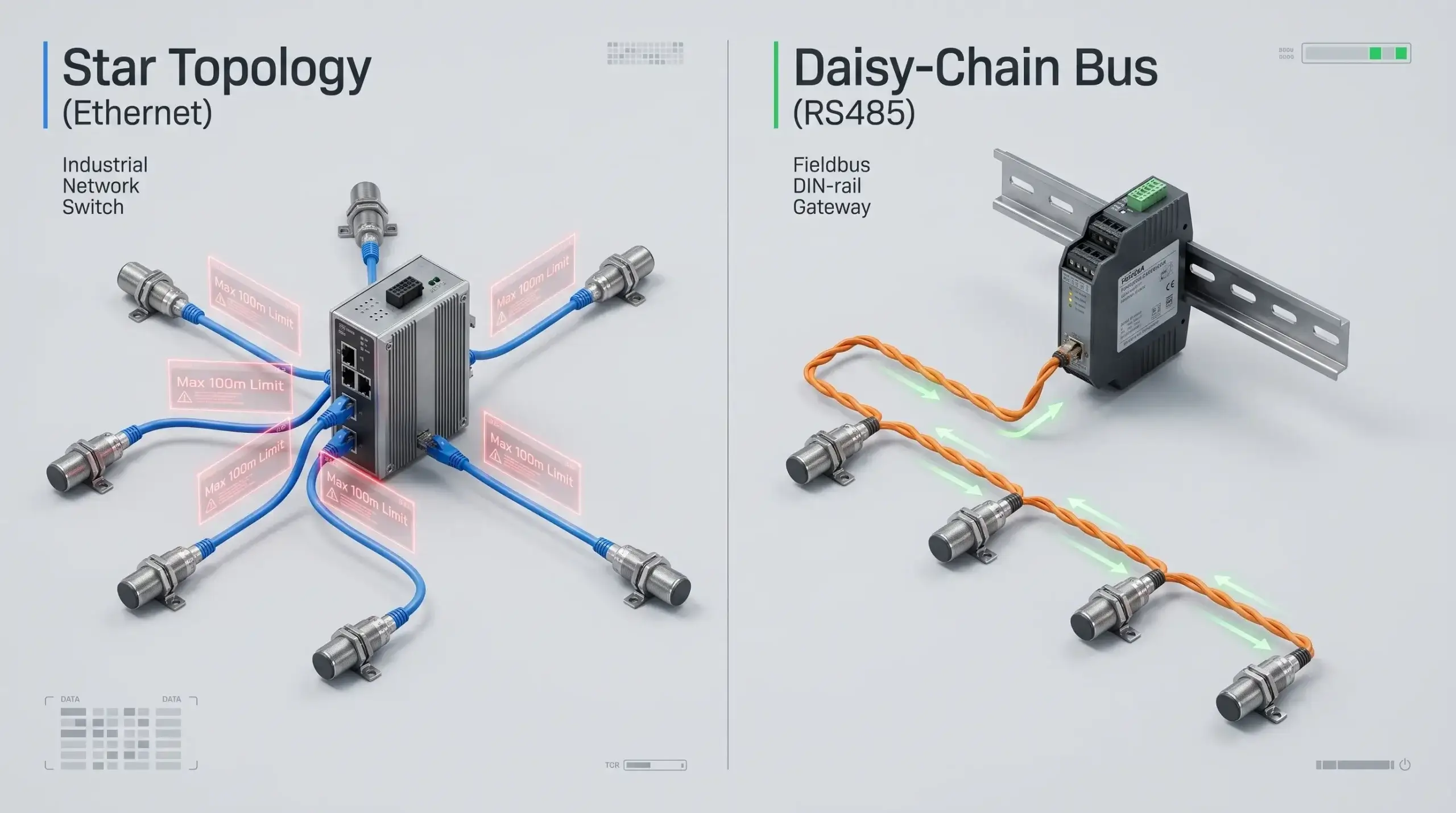
If you force Ethernet into a topology meant for RS485, you are not innovating; you are over-engineering. Let’s break down the physical constraints mathematically.
Distance and Topology: Breaking the “100-Meter Wall”
The most immediate and brutal difference between the two standards is how they physically connect devices over distance when designing field instrumentation layouts.
Star Network Flexibility (Ethernet)
Standard Ethernet (IEEE 802.3 over twisted pair) operates on a Star Topology. Each sensor or PLC must have its own dedicated cable running directly back to a central network switch. More critically, physics dictates that the strict Ethernet distance limit over standard CAT5e/CAT6 copper is exactly 100 meters (328 feet).
If you have a pipeline pressure sensor 400 meters away, you can’t just run the cable out. To extend the Ethernet distance for remote sensors you have to put powered Ethernet switches or active repeaters every 100 meters. This requires expensive IP67 enclosures, bringing power to every repeater individually, and adding multiple hardware failure points in an outdoor or hazardous environment.
Daisy-Chain Simplicity (RS485)
When analyzing Daisy chain vs Star topology for industrial wiring, RS485 shines. You do not need to run 30 individual cables from 30 sensors back to a central switch. Instead, you run a single twisted-pair cable from the gateway to Sensor 1, then from Sensor 1 to Sensor 2, and so on. As long as you install a 120-ohm termination resistor at the far ends of the physical bus to prevent signal reflection, up to 32 (or even 256 with modern transceivers) devices can share this single cable.
Conversely, evaluating the RS485 max distance shows that a differential serial signal can travel up to 1,200 meters (4,000 feet) without a single repeater. This fundamentally alters the CapEx (Capital Expenditure) equation for large-scale deployments.
Calculate the hidden hardware costs of forcing Ethernet into a linear, long-distance sensor deployment versus a standard RS485 daisy-chain.
*Assumes industrial unmanaged switches ($150/ea) required every 100m for Ethernet extension, plus dedicated homerun cabling. RS485 requires a single multi-drop cable run.
Powering the Edge: PoE vs. RS485 Local DC Loop
A frequent argument favoring Ethernet in the field is Power over Ethernet (PoE). With a single CAT6 cable, you can deliver both Gigabit data and up to 90W of power (IEEE 802.3bt) to a remote IP camera or sensor.
But when it comes to PoE vs RS485 power distribution over large industrial sites, the 100 meter PoE limit is a hard barrier. Once you exceed 100 meters, voltage drop across the thin Ethernet conductors becomes too severe to power end devices reliably without injecting power at intermediate switches.
How do instrumentation engineers solve this with RS485? They deploy a composite 4-core cable strategy. Two cores (typically 24 AWG twisted pair) carry the differential data signals. The other two cores (typically thicker 18 AWG or 16 AWG wires) carry a robust 24V DC or 12V DC power loop spanning the entire daisy-chain.
Because RS485 transceivers and industrial sensors consume very little power (often milliwatts), a standard 24V DC power supply located in the main control cabinet can easily power 30 sensors across a 1000-meter run, even accounting for voltage drop across the 18 AWG copper wires. This completely eliminates the need for expensive PoE midspan injectors in the field.
Surviving the Factory Floor: Noise Immunity in Harsh Environments
Half the battle is distance. The physical environment of a manufacturing plant or power substation is an extremely hostile environment for digital signals. Electromagnetic Interference (EMI) is generated constantly by large electrical motors, variable frequency drives (VFDs) and heavy machinery.
If you run a standard, unshielded Ethernet cable near a 480V motor, the magnetic field will induce a high-voltage spike onto the copper wires. Because standard single-ended digital communication measures voltage relative to a single ground plane, this spike corrupts the data bits. The receiving device sees a “1” instead of a “0”, causing a CRC error and a dropped packet.
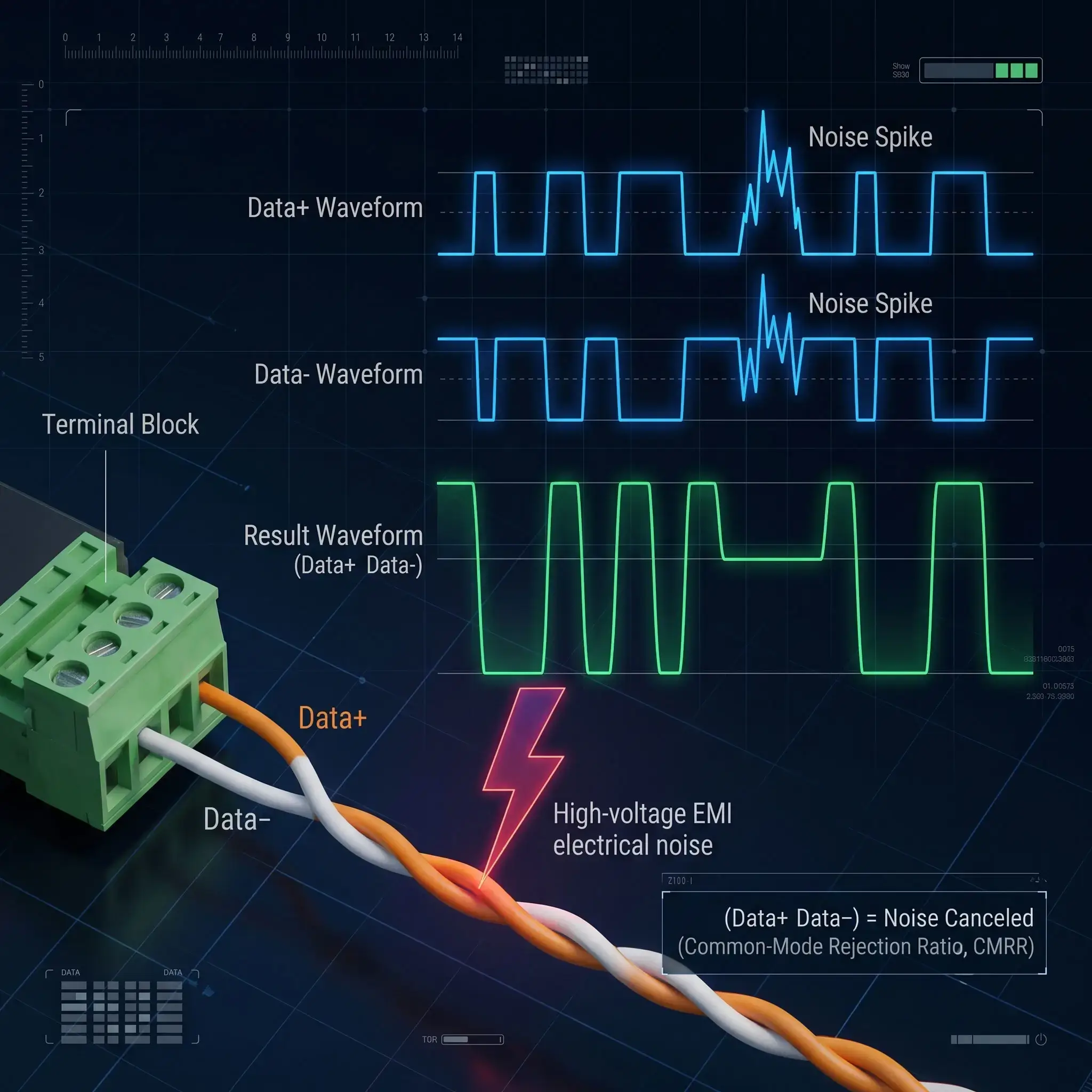
To guarantee RS485 noise immunity in harsh environments, the standard circumvents this physics problem by employing Differential Signaling. Instead of sending one signal relative to ground, RS485 uses two wires (Data A+ and Data B-). When transmitting a logic “1”, one wire goes high while the other goes low. The receiving sensor doesn’t look at the absolute voltage; it only looks at the difference between the two wires.
Single-Ended Ethernet / RS232
How EMI Destroys Frames: An external magnetic field induces a +5V noise spike onto the wire. Because voltage is referenced to ground, a logic ‘0’ (0V) suddenly reads as a logic ‘1’ (+5V). The packet is corrupted, triggering continuous retry loops and SCADA alarms.
Differential RS485 (With Isolation)
Why Noise is Canceled: The EMI spike hits both twisted wires equally (+5V on A and B). The differential receiver subtracts Wire A from Wire B. The common-mode noise mathematically cancels itself out (CMRR). When paired with 3000V galvanic isolation, field ground loops are completely blocked.
Installation Best Practices: Termination and Grounding
While the physics of differential signaling are sound, an RS485 network is only as robust as its physical installation. The vast majority of field failures are not protocol issues, but wiring errors. Two critical practices separate amateur installations from zero-downtime industrial networks:
1. The 120-Ohm Termination Resistor
When an electrical pulse hits the physical end of a copper wire, it doesn’t just vanish. If the wire is left open, the energy bounces back up the line, creating a “echo” or signal reflection. This reflection at high baud rates or over long distances collides with new data packets . This scrambles the frame .
To absorb this kinetic energy, engineers must install a 120-ohm termination resistor across the Data+ and Data- terminals of the very first device (the gateway) and the very last device on the daisy-chain. Do not place resistors on the middle nodes, as this will overload the transceiver chips.
2. Single-Point Shield Grounding
Shielded twisted pair (STP) cable is highly recommended for high EMI environments. The foil shield intercepts the electromagnetic radiation before it reaches the data cores. But a common mistake is to ground the shield at both ends of the cable.
Because different cabinets in a factory often have slight differences in ground potential, grounding both ends creates a “Ground Loop.” Massive currents will travel through your data cable’s shield to equalize the voltage, introducing severe noise. The golden rule of RS485: Always ground the shield at one end only (typically at the master gateway cabinet).
Cybersecurity at the Edge: The Inherent Isolation of Serial Buses
As ransomware attacks on critical infrastructure escalate, the push to assign an IP address to every field device via Ethernet introduces a massive attack surface. Standard Ethernet devices are routable, pingable, and vulnerable to network-wide scanning tools.
RS485, inherently, is a non-routable serial protocol. A field sensor speaking Modbus RTU over a differential pair does not have an IP address, a MAC address, or an open TCP port to exploit. It creates a natural physical air-gap at the field layer. Malicious actors cannot remotely access an RS485 valve actuator from the corporate IT network without first compromising the edge gateway bridging the two networks.
Bandwidth vs. Data Reality: Do Sensors Need Gigabit Speeds?
The strongest point in favour of Ethernet is bandwidth. Today’s standard is Gigabit (1000 Mbps) Ethernet. A typical RS485 network runs at a measly 9600 bps (0.0096 Mbps) or 115200 bps. Ethernet is a winner on paper and a winner by a mile.
But let’s examine the reality of the data payload. An industrial temperature sensor, a pressure transducer, or a flow meter does not stream 4K video. It transmits a few bytes of hexadecimal data representing a floating-point number (e.g., “Current Temp: 74.5”). Over-provisioning Gigabit bandwidth for a 4-byte payload is the equivalent of renting an 18-wheeler truck to deliver a single envelope.
Modbus RTU vs Modbus TCP Latency & Determinism
Bandwidth aside, control systems require Determinism—the guarantee that a signal will arrive exactly when expected without random delays. Standard Ethernet uses a protocol mechanism called CSMA/CD (Carrier Sense Multiple Access with Collision Detection). If two devices try to speak at the exact same millisecond, the packets collide, both back off for a random microsecond interval, and try again. In heavy traffic, this causes unpredictable jitter.
When comparing Modbus RTU vs Modbus TCP latency, RS485 operates on a strict Master/Slave hierarchy. The slave field sensors are physically incapable of speaking unless directly queried by the Master controller. There are zero collisions on a properly configured RS485 bus. The timing is 100% deterministic, preventing packet collision in sensor networks without requiring complex IT traffic shaping.
Diagnostics and Maintenance: Ping vs. Oscilloscope
If RS485 excels in physical resilience and cost, it fundamentally fails in diagnostic simplicity. This is the primary reason IT departments advocate for standard Ethernet.
For an Ethernet node down, network administrators can ping the IP address, check switch port status or use Wireshark for packet loss analysis remotely. The problem is confined to one homerun cable.
Conversely, troubleshooting an RS485 daisy-chain is notoriously difficult. If a single transceiver fails and shorts the differential bus, the entire network drops. Because it is a shared multi-drop line, identifying which of the 30 sensors is causing the collision requires an OT engineer to physically walk the plant floor, disconnect nodes one by one, and measure line voltages with a multimeter or an oscilloscope. It is a time-consuming diagnostic nightmare that intelligent edge gateways must mitigate by isolating faulty spur lines.
Bridging the IT/OT Gap: Connecting Legacy RS485 to the Cloud
If RS485 is vastly superior for long-distance, low-cost, high-noise field wiring, why does IT hate it? Because legacy RS485 devices cannot connect directly to an Ethernet SCADA system, an AWS/Azure dashboard, or an MQTT broker. Cloud systems rely on structured JSON payloads over MQTT or HTTP; legacy sensors speak raw serial hex codes.
You do not need to rip and replace thousands of dollars of reliable RS485 field sensors with expensive Ethernet sensors. The optimal architecture is a hybrid one: Run RS485 in the dirt, and use an intelligent IoT gateway to parse those hex codes directly into JSON/MQTT at the control cabinet edge.
When OT engineers ask how to connect RS485 to Ethernet networks without triggering Modbus timeouts, the definitive answer is deploying an intelligent industrial edge gateway inside the control cabinet. The RS485 terminal block faces the field sensors on the bottom, while the RJ45 Ethernet port bridges to the local switch or cloud on top.
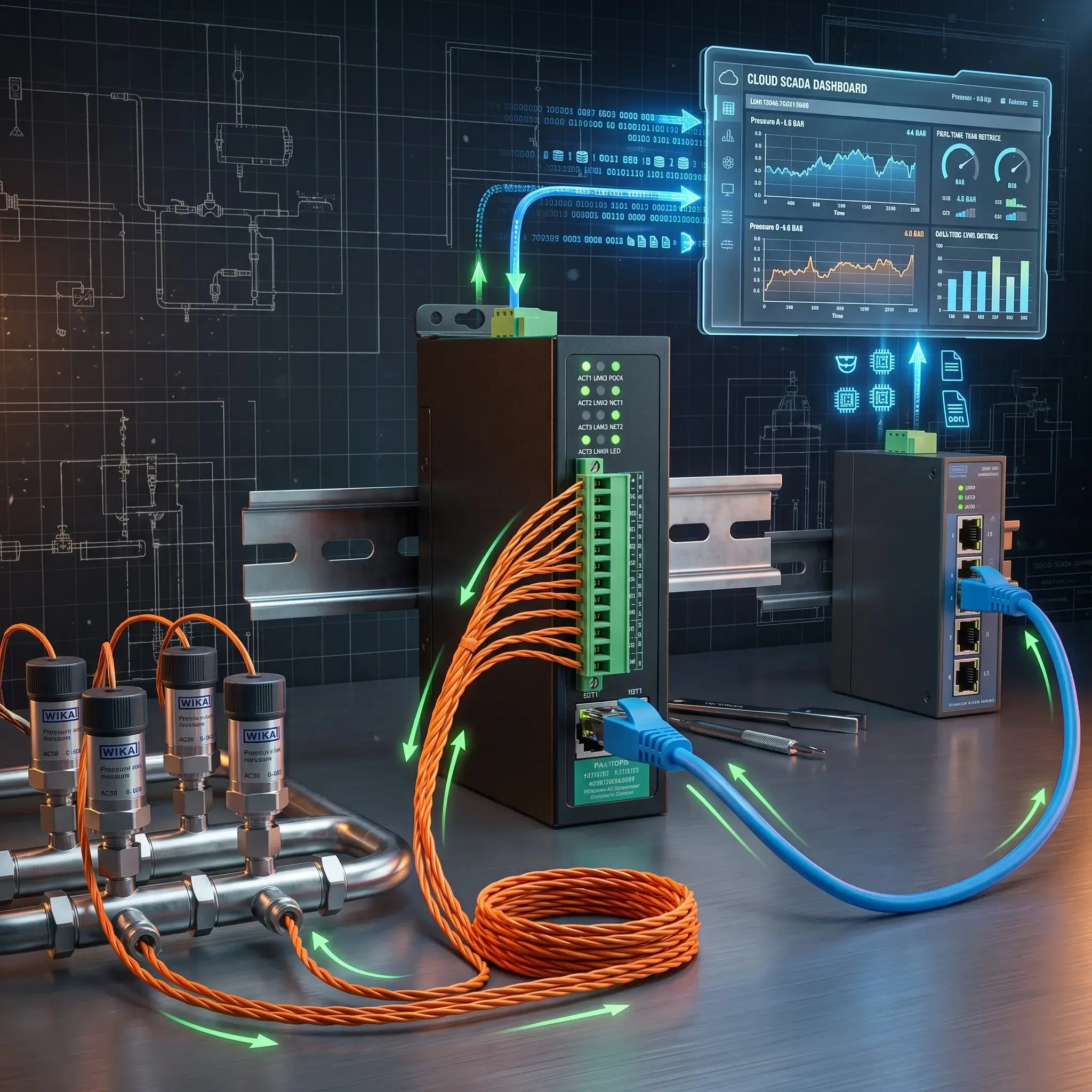
However, this is where 90% of integration projects fail. Many engineers buy a cheap, transparent “serial-to-Ethernet converter” that simply encapsulates serial hex bytes into a TCP packet blindly. When the high-speed Gigabit SCADA system queries the slow 9600-baud RS485 bus, the timing mismatch causes a massive buffer overflow, packet drops, and system freeze.
Technical Deep Dive: The Protocol Disconnect
Understanding physical wiring is only half the battle. If you want to know exactly why transparent serial servers trigger Timeout and Exception Code 0x0B during SCADA polling, read our software-layer companion guide:
Modbus RTU vs TCP: Connecting Legacy RS485 Devices to Ethernet SCADA →
To eliminate timing collisions, you must use an intelligent Modbus RTU to TCP converter featuring internal Storage Polling (Canned Polling). The gateway independently polls the field sensors at their native baud rate, stores the current values in its internal memory, and instantly responds to high-speed Ethernet SCADA queries in sub-3 milliseconds.
Case Study: Preventing Packet Collision in a 20MW Solar Network
Real-World Telemetry Retrofit
The Problem: A 20-Megawatt utility-scale solar farm was experiencing severe data dropout. The site consisted of 40 string inverters daisy-chained over an 800-meter RS485 bus. The central SCADA system (running Modbus TCP over a fiber backbone) was polling the network every 500 milliseconds.
Because the original integrators installed a low-cost transparent serial server, the SCADA requests were flooding the 9600-baud RS485 line faster than the inverters could respond. The resulting packet collisions crashed the bus multiple times a day.
The Solution: The engineering team ripped out the transparent converters and deployed the Valtoris 4CH-RS485-ETH (VI) Isolated Gateway. The device was configured to use its native “Storage Modbus Gateway” feature. The gateway mapped the 40 inverters into its onboard memory. The SCADA system now polls the memory over Ethernet at blazing Gigabit speeds, while the 4CH-RS485-ETH (VI) independently manages the slow RS485 traffic locally and protects the bus with 3000V isolation.
Result: No packet drops, 3000V isolation protected the network from ground loops during storms, and network latency dropped from seconds to less than 3 milliseconds.

Stop Modbus Timeouts with Deterministic Edge Gateways
Don’t risk SCADA lockups with dumb transparent converters. Valtoris industrial serial servers feature automated sub-3ms hardware caching and up to 3000V galvanic isolation.
1-Port RS485/232 to Ethernet Serial Server. Compact footprint designed for space-constrained control cabinets and simple sensor loops.
- Modbus RTU to Modbus TCP Protocol Conversion
- 2KV Electromagnetic Surge Protection
- Wide Operating Temp: -40°C to +85°C
4-Channel RS485 to Ethernet Modbus Gateway. Engineered for harsh substation environments with severe VFD harmonic noise.
- 3000V Galvanic Opto-Isolation Protection
- Automated Sub-3ms Hardware Storage Polling
- Multi-Master SCADA Arbitration Engine
The Final Verdict: Which Standard Fits Your Deployment?
The RS485 vs. Ethernet debate is not about finding an outright winner, it is about choosing the right physical layer for the right application. Complete your architectural blueprint using the decision matrix below.
| Criteria | RS485 (Serial Bus) | Industrial Ethernet |
|---|---|---|
| Max Distance (No Repeaters) | Up to 1,200 meters (4,000 ft) | 100 meters (328 ft) |
| Topology | Daisy-Chain (Multi-drop) | Star (Requires Switches) |
| Hardware Cost per Node | Extremely Low | High (Requires IP stack & PHY) |
| EMI Noise Immunity | Excellent (Differential signaling) | Moderate (Requires STP/Fiber) |
| Bandwidth | Low (Max ~10 Mbps) | Massive (1 Gbps+) |
| Cloud / IT Compatibility | Requires an RS485 to Ethernet Gateway | Native (TCP/IP ready) |
| Best Use Case | Distributed temperature, pressure, flow sensors across large facilities. | Machine vision cameras, high-speed motion control, PLC-to-PLC comms. |
In modern industrial automation, the most resilient networks are hybrid. By deploying rugged, low-cost RS485 networks in the field and terminating them into intelligent, protocol-translating Modbus gateways at the cabinet edge, you satisfy both the OT engineer’s need for physical reliability and the IT department’s demand for seamless cloud integration.
Frequently Asked Questions (Architecture & Field Deployment)
Can I really put 256 devices on a single RS485 bus, or is 32 the absolute limit?
Can I use standard CAT5/CAT6 Ethernet cable for wiring an RS485 network?
What happens if I mix devices with different baud rates on the same RS485 daisy-chain?
If one sensor dies or shorts out on an RS485 daisy-chain, does the whole network go down?
When should I choose Fiber Optic conversion over RS485 for long-distance runs?
Architecting a New Sensor Network? Let Us Review Your Topology
You don’t have to roll the dice when it comes to serial buses vs. Ethernet backbones. Simply share your sensor node count, maximum distance and environmental noise profile and our network architects will analyze your layout and advise you on the exact conversion hardware required for a zero-drop deployment.
Request a Free Architecture Review →