
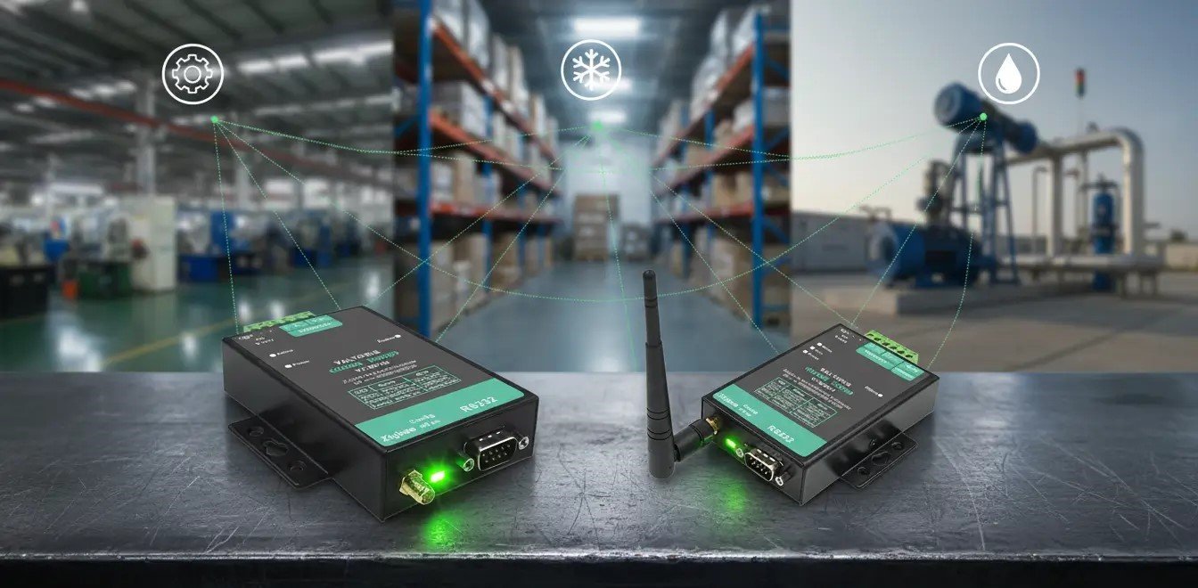
Let’s begin with an uncomfortable engineering truth that most IoT marketing brochures refuse to admit: Zigbee is not a magic bullet for industrial automation.
As a controls engineer, SCADA architect or systems integrator, you have no doubt been sold on a plethora of “smart factory” Zigbee solutions promising to seamlessly replace every RS485 and Ethernet cable on your factory floor. The reality we find in the field is quite different. Poorly deployed wireless networks in heavy industry fail catastrophically, bringing production lines to a grinding halt and setting off endless nuisance alarms on the HMI.
However, when deployed correctly—respecting the strict physics of RF propagation and the limitations of the IEEE 802.15.4 standard—industrial Zigbee is arguably the most reliable, cost-effective telemetry data collection tool available today. The key to successful Zigbee industrial automation lies not in forcing the technology to act as a hardwired replacement for high-speed deterministic control systems, but in leveraging it exclusively for what it does best: distributed, self-healing, low-bandwidth data aggregation across massive facilities.
This comprehensive engineering guide will dissect the brutal realities of deploying Zigbee in harsh industrial environments. We will face the facts about electromagnetic interference (EMI), explain the catastrophic “DDoS Trap” of high-frequency polling, bridge the IT/OT gap with Modbus TCP gateways, and conduct a ruthless, brand-name comparison of real Zigbee products on the market today to help you select the exact architecture your project demands.
Table of Contents
- 1. The Reality of 2.4 GHz in the Factory: Surviving VFDs and EMI
- 2. The “DDoS” Trap: Why High-Frequency Telemetry Kills Zigbee Meshes
- 3. Bridging the IT/OT Gap: Top Zigbee-to-Modbus TCP Gateways
- 4. 2026 Industrial Vendor / Scenario Comparison
- 5. Beyond the Spec Sheet: The Invisible Engineering Traps
- 6. The Golden Rule of Industrial Wireless: Hardwire the Control, Zigbee the Telemetry
- 7. Frequently Asked Questions
⚡ Telemetry Viability Engine
Before evaluating hardware, input your application’s data profile to determine if it violates the physical constraints of an industrial 802.15.4 mesh network.
The Reality of 2.4 GHz in the Factory: Surviving VFDs and EMI
Walk onto the floor of any modern steel mill, wastewater treatment plant or automotive manufacturing facility and you are immediately immersed in a chaotic and invisible spectrum of electromagnetic interference (EMI). Huge induction motors drawing huge inrush currents, arc welders firing off sporadically, and sprawling arrays of Variable Frequency Drives (VFDs) chopping voltage at high kilohertz frequencies make a formidable noise floor that kills fragile RF communications.
A sentiment frequently echoed by veteran controls engineers on industry forums is a variation of this exact story: “We installed a highly-rated consumer smart-hub and a 2.4 GHz wireless module next to our main 100HP VFD cabinet. The moment the drive ramped up, the network dropped offline, the packets collided, and our SCADA screens went blind.”
The catastrophic failure occurs because standard 2.4 GHz signals (the same frequency spectrum used by commercial Wi-Fi routers and Bluetooth headsets) are very susceptible to being drowned out by electrical broadband noise if the RF transceiver design is not done well. No real industrial Zigbee product is built with standard consumer silicon to survive and thrive in this hostile environment. Instead they use specific hardware architecture and protocol level reinforcements as needed by industrial engineering standards.
First and foremost, industrial Zigbee utilizes the IEEE 802.15.4 standard protocol, which fundamentally relies on Direct Sequence Spread Spectrum (DSSS) modulation. This is not the case with narrow-band transmissions (a single harmonic from a VFD can easily jam them). DSSS intentionally spreads the original signal over a much wider frequency band. It does this by multiplying the data being sent with a “noise” signal, a pseudorandom sequence of 1s and 0s. Hence, even in the presence of a specific strong frequency spike in the environment, the fundamental mathematical sequence of the data remains intact and can be reconstructed by the receiver. This allows for a deep anti-jamming against usual factory noise.
Furthermore, to literally pierce through the high noise floor, raw transmission power and receiving sensitivity are paramount. For example, industrial edge nodes like the Valtoris VT-ZIGBEE700 series are engineered with a receiving sensitivity of -105dbm and a transmit power of 25dbm. This specific combination of a high-power Power Amplifier (PA) and an ultra-sensitive Low Noise Amplifier (LNA) ensures that the Zigbee signal “shouts louder” than the background EMI and “listens closer” to faint responses from distant nodes.
Finally, we must address the physical layer and the reality of industrial enclosures. RF signals absolutely do not penetrate solid steel well. Placing a Zigbee node containing an internal PCB trace antenna inside a grounded, NEMA 4 / IP66-rated steel control cabinet effectively creates a Faraday cage, killing the signal entirely.
This physics problem is completely avoided with external SMA male head antenna connectors used for industrial products. This design allows the engineers to safely mount the actual transceiver on a DIN rail in the protected cabinet, with the PLCs, while running a coaxial extension cable to a magnetic base antenna mounted on the outside roof of the enclosure. It is a simple hardware feature that guaranties a clear unobstructed line of sight across the factory floor, with a transmission distance of up to 2000m in the open.
However, pure transmission distance is meaningless if a forklift parks directly between your sensor and the gateway. This is where true Zigbee Mesh topology saves the day. Unlike point-to-point Wi-Fi, industrial Zigbee nodes act as redundant routers. If physical line-of-sight is blocked, the network instantly self-heals, automatically finding a new multi-hop path around the steel obstruction to deliver the Modbus packet. While open-air range hits 2000m, a properly deployed mesh ensures reliable 100-300m hops right through dense indoor factory layouts.
| Interference Source | Consumer Equipment Vulnerability | Industrial Zigbee Mitigation Strategy |
|---|---|---|
| Variable Frequency Drives (VFDs) | Wideband electrical noise causes immediate packet loss and connection dropping. | DSSS modulation mathematically reconstructs data streams despite massive noise spikes. |
| Heavy Steel Control Cabinets | Internal PCB antennas lose >90% of signal strength due to the Faraday Cage effect. | External SMA antennas routed and magnetically mounted to the cabinet exterior. |
| Dense 2.4 GHz Factory Wi-Fi | Wi-Fi channel overlap causes severe data collisions and high latency. | CSMA-CA anti-collision loops and specific non-overlapping channel selection. |
| Large Physical Distances | Signal drops entirely past 30-50 meters indoors. | 25dbm transmit power achieving up to 2000m transmission distance. |
 The VT-ZIGBEE700 features an external SMA antenna connector and 9-24V DC terminals. These are not premium upgrades; they are bare minimum requirements for industrial survival.
The “DDoS” Trap: Why High-Frequency Telemetry Kills Zigbee Meshes
Perhaps the most fatal mistake made by IT professionals transitioning into the OT space is treating a wireless mesh network like a gigabit Ethernet fiber backbone. Zigbee is intentionally designed as a low-power, low-bandwidth standard. When an engineer configures their SCADA system to poll a wireless Modbus sensor 100 times per second, they are essentially launching a Distributed Denial of Service (DDoS) attack against their own network infrastructure.
To understand why this is the case, we must look at how the mesh routes traffic. In a Zigbee mesh, nodes are also routers, actively routing data payloads for other nodes that are not within direct range of the central gateway. The standard IEEE 802.15.4 adopts an anti-collision loop protocol, Carrier-Sense Multiple Access with Collision Avoidance (CSMA-CA)..
In simple terms: before a node is allowed to transmit data, it must first “listen” to the RF channel. If it hears that the channel is currently busy (because another node is transmitting), it backs off, waits a random duration, and tries again. If you flood the mesh network with high-frequency data—such as trying to stream real-time vibration analysis waveforms, high-speed camera feeds, or millisecond-level power quality data—every node in the network is constantly trying to talk simultaneously. The channel remains perpetually busy. Nodes continuously back off, data queues overflow, and the entire mesh collapses under the crushing weight of its own collision avoidance algorithms.
Also the strict physical limits of the hardware buffers must be considered. For devices such as the VT-ZIGBEE series, the maximum packet size is strictly limited to 100 bytes. Trying to push a large block of Modbus registers past this limit will force the system to break the data into smaller chunks, exponentially increasing the RF traffic, compound the CSMA-CA delays, and increase the latency until the master PLC times out.
So, if it cannot handle high-speed data, what is Zigbee actually designed for? Slow, deliberate Telemetry.
Industrial telemetry involves the automated communication of measurements at remote points to centralized receiving equipment. It is characterized by slow, intermittent, or exception-based updates. Are you checking the fluid level of a remote chemical tank every 5 minutes? Zigbee is perfect. Monitoring the ambient temperature of a massive cold storage warehouse every 30 seconds? Ideal. Tracking the pressure of a widespread water pipeline network? Flawless.
Industrial Zigbee is extremely robust when used for what it is meant for. For example, a good telemetry network can realize duplex transmission at less than 38400bps in high performance node without losing packets, which guaranties the absolute data smoothness.
| Application / Scenario | Typical Data Frequency | Engineering Rationale & Verdict |
|---|---|---|
| Remote Tank Level (Water / Chemical monitoring) | Every 1 to 5 minutes | Optimal for Zigbee: Extremely low bandwidth. Data easily fits within the 100-byte max packet size. The mesh seamlessly routes data around large physical tanks. |
| Motion / Servo Control (VFD Torque matching) | 1 to 5 milliseconds | Catastrophic: Requires absolute deterministic communication. CSMA-CA introduces variable latency, which will immediately cause drive faults. Hardwire only. |
| HVAC / Environmental (Cold storage temp mapping) | Every 30 to 60 seconds | Optimal for Zigbee: Ambient temperatures change slowly. This infrequent data polling does not congest the network, allowing hundreds of sensors to coexist. |
| Safety Relays (E-Stop) (Light curtains, interlocks) | Instantaneous | Catastrophic: Life-safety systems must NEVER rely on wireless mesh architectures due to the inherent possibility of RF interference or node failure. Hardwire only. |
| Energy Meter Aggregation (Power consumption monitoring) | Every 15 minutes | Optimal for Zigbee: Easily handles periodic polling of Modbus energy registers over the network for billing or efficiency trending without stressing the mesh. |
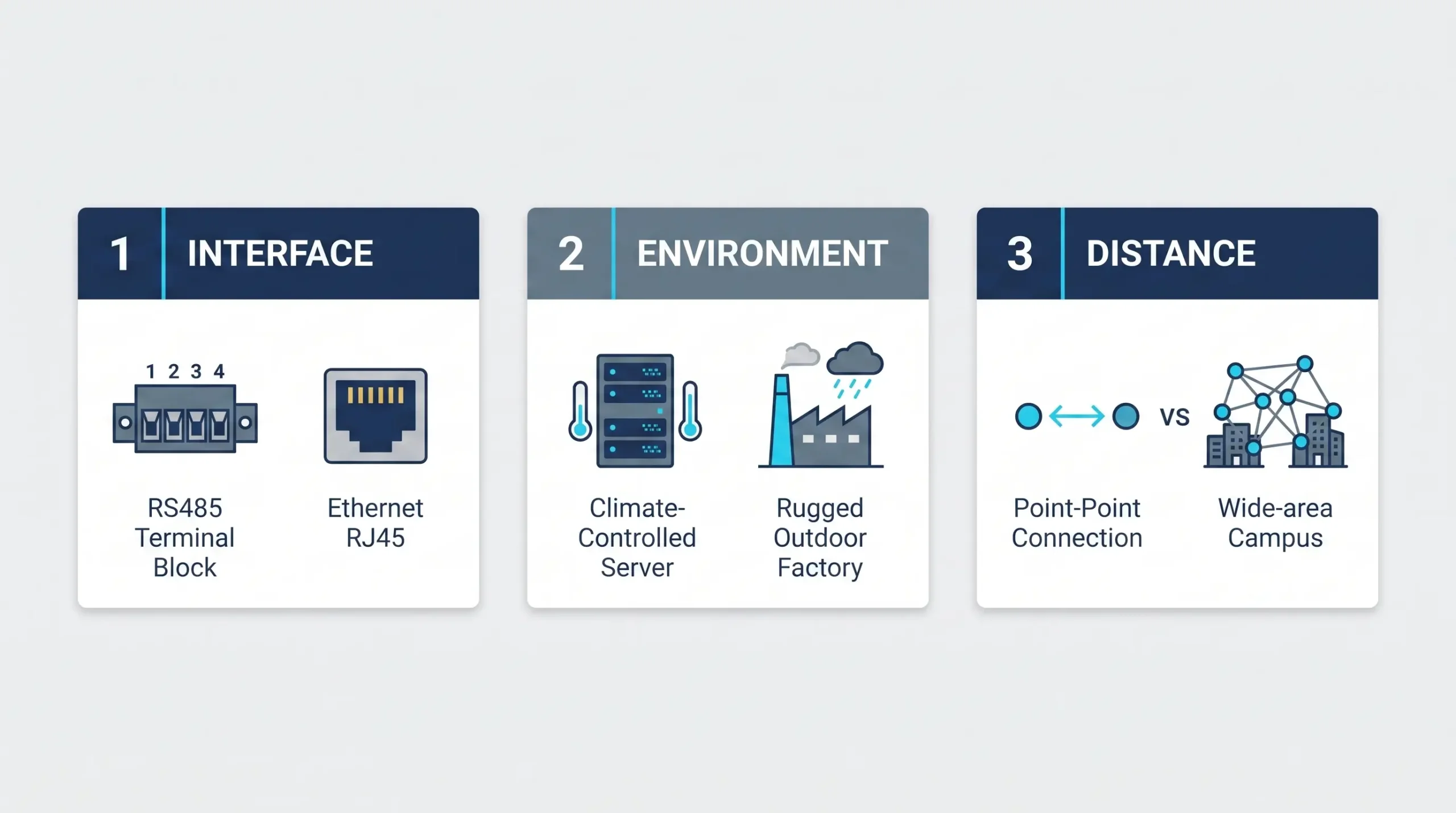 Before establishing network modes, engineers must strictly define what interfaces are being connected and where they are physically located to bridge the IT/OT gap correctly.
Bridging the IT/OT Gap: Top Zigbee-to-Modbus TCP Gateways
Once you have established a stable, low-frequency telemetry network on the physical floor, an entirely new challenge arises in the control room. Operational Technology (OT) edge devices (like flow meters, VFDs, and temperature controllers) typically speak serial protocols via RS232, RS485, or RS422. Conversely, Information Technology (IT) infrastructure and modern SCADA systems, PLCs, and cloud dashboards demand Ethernet and TCP/IP protocols.
Bridging this inherent gap is where raw, DIY wireless modules completely fail, and finding the best Zigbee gateway for your specific architecture demonstrates its immense value. Consider a facility with 40 legacy Modbus RTU flow meters connected via RS485. Running thousands of feet of copper cable back to a central control panel is cost-prohibitive. You need a device that acts as a wireless translator.
This is the exact function of the VT-ZIGBEE701. It is not merely a radio antenna; it possesses the multi-function capability of converting Zigbee to Ethernet, realizing Zigbee to TCP/IP. When remote serial devices connected to VT-ZIGBEE700 edge nodes send their data through the mesh, the central VT-ZIGBEE701 node receives that data and transparently converts the serial data into TCP/IP packets to transfer to the network server.
More importantly for controls engineers, the gateway handles complex protocol conversion natively. Through the device’s web configuration interface, the transfer protocol can be explicitly set to Modbus TCP <-> RTU. This feature is a massive time-saver. It means the gateway will convert the modern Modbus TCP protocol directly into the legacy RTU protocol. Your modern Rockwell or Siemens PLC can simply poll the IP address of the gateway using standard Modbus TCP. The gateway then seamlessly queries the remote RS485 sensor over the wireless mesh, waits for the reply, translates it back into Modbus TCP, and hands it to the PLC. No complex PLC string-parsing logic is required.
Also, these industrial gateways provide deep network flexibility to support a wide variety of IT architectures. They can be configured to operate as a TCP Server, TCP Client, UDP Mode or UDP Multicast mode.
What if you are dealing with legacy PC-based HMI software that was written 15 years ago and absolutely demands a direct “COM Port” connection? Industrial solutions account for this by utilizing virtual serial port software. For instance, the Valtoris suite includes a tool called Vircom. This Windows-based software can search for devices across the network and bind the current device to a created virtual serial port. Your legacy software opens “COM5”, completely unaware that the data is being routed over an Ethernet LAN to the gateway, and then broadcast over a 2.4 GHz DSSS mesh to a sensor on the other side of the plant.
| Network Mode | How it Works (Architecture) | Primary Industrial Use Case |
|---|---|---|
| TCP Server | The network server (e.g., PLC/SCADA) actively initiates the connection to the gateway. | Standard SCADA polling; the master controller requests data from remote nodes on a set schedule. |
| TCP Client | The gateway actively initiates the connection to a designated destination IP address. | Pushing data to remote cloud servers or centralized databases; it automatically reconnects upon restart to push data outward. |
| UDP Mode | Connectionless data transmission broadcasted to a destination IP/Port. | Fast telemetry broadcasting where occasional packet loss is acceptable but high speed and low overhead are desired. |
| Virtual Serial (Vircom) | Software binds a virtual Windows COM port directly to the gateway’s IP address. | Integrating legacy HMI software that only understands physical COM ports, tricking it into reading network data. |
Choosing the Right Industrial Connectivity Solution
Start with what you already have. The right products become obvious once you answer these questions.
2026 Industrial Vendor / Scenario Comparison
When Original Equipment Manufacturers (OEMs) and systems integrators first begin researching Zigbee for a project, they must navigate a fragmented market. Some products are bare silicon modules requiring intense programming; others are legacy enterprise systems costing thousands of dollars. To successfully deploy Zigbee, you must align the product’s architecture with your specific engineering constraints.
To help you choose, we have compiled an objective comparison of the best Zigbee products across different technological approaches. We are not ranking them from best to worst; every product here serves a specific market perfectly. Your job is to identify which tier your project requires.
Digi ConnectPort X4
Large enterprise IT deployments requiring deep edge computing, VPN tunneling, and cellular backhaul.
The absolute gold standard in enterprise IoT. Supports Python scripting directly on the gateway. Massive global support network and cloud ecosystem (Digi Remote Manager).
Extremely high brand premium and procurement cost. Overly complex for a field technician who just needs to transparently bridge a Modbus RTU sensor. Requires coding knowledge to maximize value.
Advantech ADAM-4530 Series
Heavy industrial facilities (Oil & Gas, Mining) that exclusively mandate Tier-1 legacy brand hardware on their vendor lists.
Legendary ruggedness and brand trust. Integrates flawlessly with the massive Advantech ADAM ecosystem of remote I/O modules. Excellent DIN-rail form factor.
High cost. The configuration software can feel dated. Procurement lead times can be lengthy compared to agile manufacturers.
ICP DAS ZT-2570
Traditional factory automation projects heavily dependent on the proprietary DCON protocol and the larger ICP DAS ecosystem.
Great visual topology software (ZT Configuration Utility). Reliable mesh generation. Significant presence in Asian manufacturing markets.
A small brand premium. For first time users stepping outside their ecosystem the learning curve for their specific DCON/Modbus mapping software can be steep.
Valtoris VT-ZIGBEE Series
System integrators who need instant, plug-and-play Modbus RTU-to-TCP bridging without writing any code, maximizing project ROI.
Unbeatable value and speed of deployment. Combines RS232/485/422 in one unit. Built-in Modbus TCP-to-RTU conversion. True industrial specs (9-24V, -40℃ to 85℃).
Lesser global brand recognition compared to legacy giants like Advantech. Does not support Python edge-computing scripts natively on the gateway.
Beyond the Spec Sheet: The Invisible Engineering Traps
Even if you purchase the best industrial Zigbee gateway on the market, your project will still fail if you do not understand the invisible engineering traps inherent to wireless telemetry. Experienced integrators know that the spec sheet only tells half the story. Here are the three most common pitfalls that ruin factory deployments, and how to avoid them.
Trap 1: The SCADA Timeout Trap
This is the number one reason engineers mistakenly believe their new Zigbee network is “broken.” When polling a sensor over a hardwired RS485 cable, the response time is nearly instantaneous. Therefore, default Modbus polling timeouts in PLCs and SCADA software are often set very aggressively—typically around 50ms to 100ms.
When you transition to a Zigbee mesh, the data must travel over the air, potentially hop through several routing nodes, get translated by the gateway, and then travel over Ethernet. This inherent RF latency means the response might take 300ms to 800ms. If your PLC timeout is still set to 50ms, the PLC will give up and throw a “Comm Error” before the Zigbee data even arrives. The Fix: Always increase your SCADA/PLC Modbus timeout settings to at least 1000ms (1 second) when integrating a wireless mesh network.
Trap 2: The Wi-Fi Channel Overlap
We discussed EMI from motors, but what about IT interference? Zigbee and standard factory Wi-Fi both share the 2.4 GHz ISM band. If you plug in a Zigbee gateway without checking the channels, it might attempt to transmit directly on top of your factory’s main Wi-Fi router, resulting in massive packet loss. The Fix: Wi-Fi heavily dominates channels 1, 6, and 11. The IEEE 802.15.4 standard gives Zigbee 16 specific channels to choose from. You must explicitly configure your Zigbee gateway to operate on the “gap” channels—specifically Zigbee channels 15, 20, 25, or 26. These frequencies slot perfectly between the Wi-Fi peaks, ensuring your telemetry network runs cleanly.
Trap 3: Network Cross-Talk
In a large facility you may have several different vendors or machines running their own Zigbee networks. If you leave everyone at the factory defaults, the nodes will try to join the wrong networks and you’ll have chaos. The Fix: Don’t ever use the same Network ID (0000 to FFFF) for your specific mesh. The gateway and all of its child nodes must have the same Network ID . This creates a secure, isolated topology that ignores cross-talk from neighboring systems .
Trap 4: Unencrypted OT Payloads
With the rise of industrial cyberattacks, broadcasting raw Modbus RTU telemetry data over an open 2.4GHz frequency is a massive security liability. If a rogue device sniffs your factory floor network, your OT data is compromised. The Fix: Never use bare-bones hobbyist radios for sensitive data. Ensure your industrial Zigbee gateway utilizes the IEEE 802.15.4 standard’s native AES-128 hardware encryption. This ensures that even if a packet is intercepted in the air, the payload remains completely unreadable to unauthorized devices.
| Protocol | Typical Range | Data Rate / Payload | Best Industrial Use Case |
|---|---|---|---|
| Zigbee (802.15.4) | Up to 2000m (Line of sight) | Medium (38400bps, 100 byte frames) | Dense factory floor sensor networks; Modbus RTU bridging. |
| Wi-Fi (802.11) | 30 – 100m (Indoors) | High (Mbps to Gbps) | High-bandwidth SCADA screens; Video surveillance. |
| LoRaWAN | Up to 15km (Outdoors) | Extremely Low (kbps) | Agricultural monitoring; Smart city utility metering. |
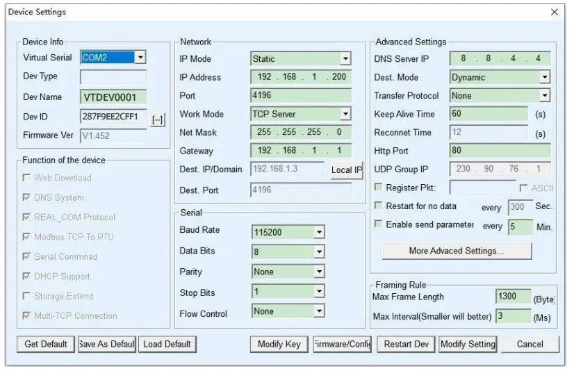 Using virtual serial port software allows legacy HMI systems to communicate over Ethernet to remote Zigbee nodes seamlessly.
The Golden Rule of Industrial Wireless: Hardwire the Control, Zigbee the Telemetry
To conclude, when implementing industrial automation using Zigbee, the long-term success of your deployment relies entirely on adhering to the golden rule of automation infrastructure: If a signal failure could result in machine damage, production downtime, or safety hazards to personnel, you run a physical hardwire. If you are collecting data for analysis, monitoring, predictive maintenance, or SCADA visualization, you use wireless telemetry.
Physical hardwiring gives you the absolute, deterministic uptime needed for high speed I/O, safety relays, and closed loop PID control. Wireless technologies, industrial Zigbee gateways in particular, are meant to eliminate the large labor costs, cable tray congestion and physical limitations of running thousands of feet of copper just to read a flow meter or temperature sensor.
By deploying good quality metal enclosed wide voltage Zigbee gateways specifically designed for industrial use and respecting the bandwidth limits of 2.4 GHz physics you can build a telemetry network that will work flawlessly alongside your critical hardwired control systems for years to come.
| Application / Scenario | Operational Requirement | Recommended Technology |
|---|---|---|
| Real-time Safety Intervention (Light curtains, E-Stops, interlocks) | Must not fail. Zero latency required. Failsafe state mandatory. | Hardwire (CIP Safety, ProfiSafe) |
| High-Speed Sorting / Motion Control (VFD torque control, servo positioning) | Requires deterministic millisecond delivery with zero jitter. | Hardwire (Profinet, EtherCAT, Ethernet/IP) |
| Remote Pump Station Status (Level, flow, basic on/off status) | Trenching physical cable is cost-prohibitive or geographically impossible. | Zigbee / Wireless (Point-to-point converters or Mesh) |
| Legacy Serial Meter Aggregation (Dozens of Modbus RS485 power meters) | Cables degrade over time; requires centralized data gathering without pulling new wire. | Zigbee (Mesh network to a central Ethernet Gateway) |
| Predictive Maintenance Trending (Motor vibration, ambient heat mapping) | Data is needed periodically for analytics, but is non-mission critical to machine operation. | Zigbee (Low frequency updates, 1-5 minute intervals) |
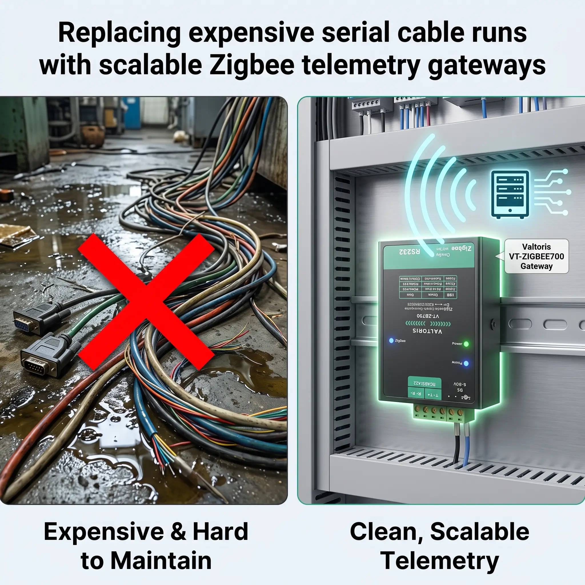 Migrating from vulnerable, miles-long copper cable runs to a distributed Zigbee mesh topology drastically reduces maintenance overhead and points of physical failure.
Frequently Asked Questions: Field Deployments & Troubleshooting
Beyond initial setup, here are the real-world operational questions integrators ask when pushing industrial Zigbee meshes to their limits.
Q: How many RS485 sensors can I practically connect to a single Zigbee coordinator?
The VT-ZIGBEE network ID can logically support 65,535 nodes (0000~FFFF) but the actual limit is determined by your Modbus polling times. Since the mesh is serially processing data , the PLC will need to wait for a response from Node 1 before polling Node 2 . For larger installations just deploy a second gateway on a different zigbee channel.
Q: If my SCADA goes blind, how do I know if the gateway is dead or if the sensor dropped offline?
Don’t guess use the hardware diagnostics. Check the LED panel for VT-ZIGBEE series: A solid Green ‘LINK’ light indicates the RJ45 Ethernet is connected and Blue indicates the TCP connection to your SCADA is active. The mesh is connected by a solid blue ‘Zigbee’ light. If the ‘ACT’ light is blinking green or blue, data is passing thru the RF network to your serial/Ethernet port.
Q: Can I power these nodes directly from the 24VDC sensor supply on my existing PLC cabinet?
Yes, the industrial nodes are just for this. The VT-ZIGBEE series has a wide 9-24V DC input via standard terminal blocks. Their power consumption is also very low – the VT-ZIGBEE700 edge node is about 50mA@9V, and the 701 gateway settles down to about 220mA@9V, so they’re not going to tax your existing panel power supplies.
Q: If deployed outdoors, do I have to open the panel to change its IP address or baud rate?
Nope. VT-ZIGBEE701 can be configured remotely via IT. You can access its built-in Web Browser interface by its IP address or use the Vircom software over your LAN to remotely change baud rates, transfer protocols and working modes (TCP Server/Client) without ever physically opening the NEMA enclosure.
Q: Does the gateway automatically poll the Modbus sensors, or does my PLC still manage the polling?
Your PLC remains in complete control. The gateway acts as a transparent bridge. When set to the ‘Modbus TCP <-> RTU’ transfer protocol, your PLC (acting as the Master) dictates the polling frequency. The gateway receives the TCP request, translates and broadcasts it over Zigbee to the specific RTU slave, waits for the sensor’s reply, and formats it back into a Modbus TCP packet for your PLC.
Stop Fighting Cable Maintenance. Start Scaling Your Data.
Don’t let legacy wiring or consumer-grade hardware hold back your facility’s digital transformation. Deploy true industrial-grade Zigbee mesh networks today.
