

For engineers dealing with industrial automation and telemetry, the need to extend a Modbus RTU network with physical RS485 cabling is often not possible due to geography or cost. Cellular (4G/LTE) gateways are a compelling alternative, but they necessitate ongoing data plans and depend on third-party network coverage, which is often spotty at best in remote facilities, agricultural locations, or underground utilities.
Industrial LoRa devices are used as transparent long-range wireless serial links to connect isolated nodes without incurring continuous OpEx. Such devices operate in license free sub-GHz bands, allowing SCADA systems to poll remote PLCs and sensors over distances measured in kilometers independent of any internet service provider.
In this technical guide, we will cover the physical layer mechanics of LoRa, the key architectural differences between Point-to-Point LoRa and LoRaWAN, and the engineering principles needed to successfully deploy a private sub-GHz network in industrial environments.
Capital Expenditure (CapEx) Estimator: Hardwiring vs. Private Wireless Bridge
Use this calculator to quantify the estimated upfront infrastructure costs of trenching standard RS485 conduit versus deploying an industrial point-to-point wireless LoRa bridge.
*Note: Estimates exclude SCADA integration labor and antenna mast installation costs.
What is a LoRa Device? Understanding the Physical Layer
A LoRa device is essentially a hardware node with a radio transceiver using Long Range (LoRa) modulation. LoRa is a proprietary physical layer (PHY) wireless technology developed and patented by Semtech for Low-Power Wide-Area Networks (LPWAN).
To understand how a LoRa device can communicate over unimaginable distances, at very low power, we need to understand its modulation scheme. FSK is typically used in traditional industrial wireless links (such as early 900MHz serial radios). FSK changes the frequency of the carrier signal a bit to encode the data. While efficient, FSK demands a relatively high Signal-to-Noise Ratio (SNR). If the signal strength drops below the background thermal noise floor the receiver cannot decode the data.
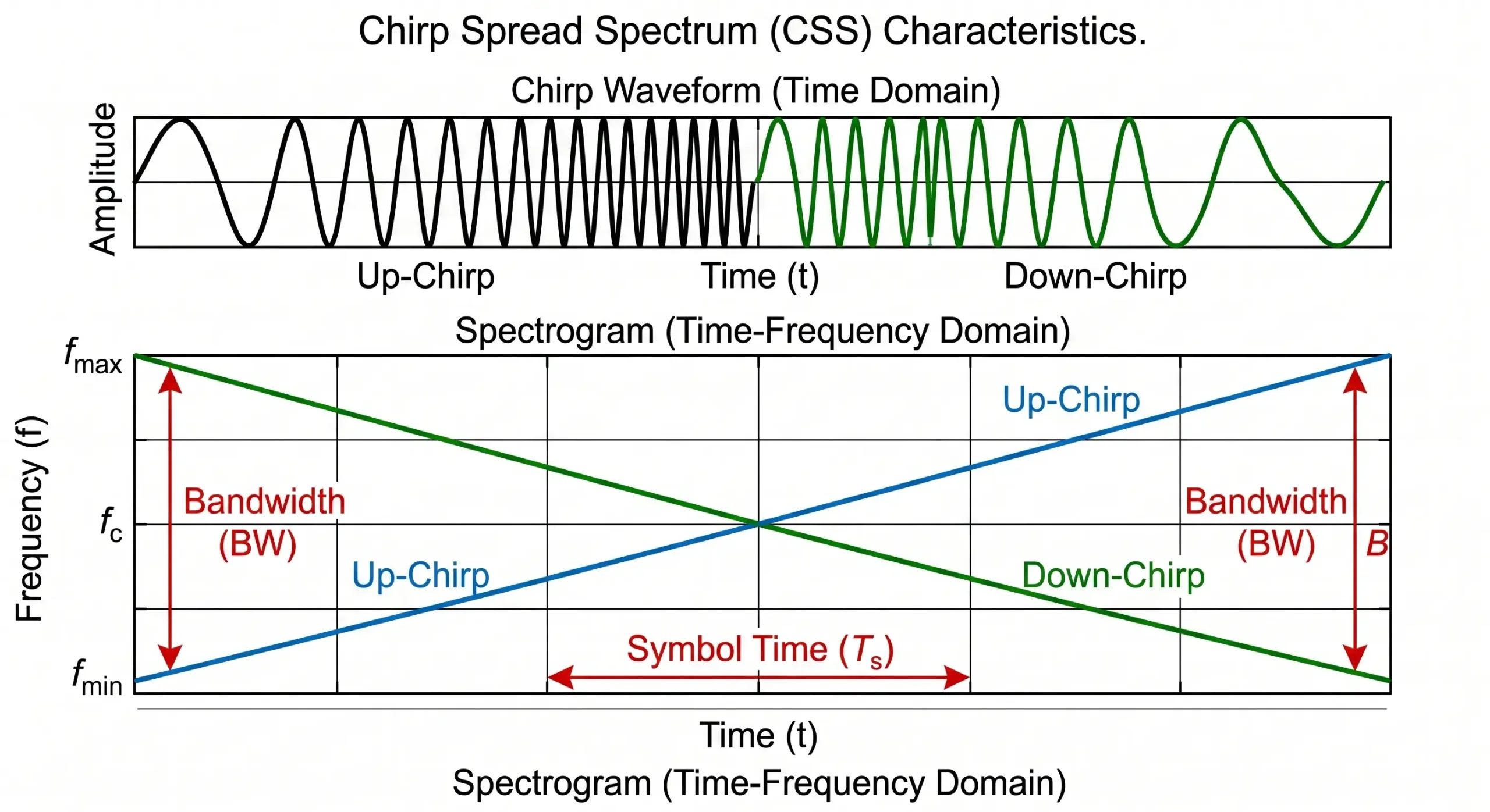
LoRa replaces FSK with a technique called Chirp Spread Spectrum (CSS). Instead of occupying a narrow frequency band, CSS spreads the signal across a wider bandwidth by generating continuous frequency-swept pulses, known as “chirps.”
It does so by exploiting the Shannon-Hartley theorem which states that the channel capacity is a function of bandwidth and signal-to-noise ratio. CSS takes advantage of a wider bandwidth for a large processing gain. Thus, a commercial LoRa receiver is capable of demodulating and decoding a signal 19.5 dB below the RF noise floor. In practical terms, this means that an industrial LoRa device transmitting at just +20 dBm (100 mW) can maintain a reliable data link over several kilometers, going around obstacles that would instantly interfere with a standard Wi-Fi or Bluetooth signal.
Clearing the Confusion: LoRa vs. LoRaWAN
The biggest architectural mistake I see in automation engineering is to confuse “LoRa” with “LoRaWAN”. Marketing literature often uses the two terms interchangeably, but they actually describe entirely different layers of the Open Systems Interconnection (OSI) model.
LoRa is the Physical Layer (Layer 1). It defines the hardware physics: the radio chips, the CSS modulation, the frequencies (e.g. 868 MHz or 915 MHz) and the output power. It provides for the raw transmission of bits over the air, but has no logic built in for device addressing, network routing, or payload encryption.
LoRaWAN is the Media Access Control (MAC) and Network Layer (Layer 2 & 3). Maintained by the LoRa Alliance, LoRaWAN is a software protocol specification built on top of LoRa modulation. It specifies a very structured “Star-of-Stars” network architecture. In a LoRaWAN deployment, end nodes send packets encrypted with AES-128 to carrier-grade Gateways. These gateways act as transparent bridges that relay the packets over an IP network (Cellular or Ethernet) to a centralized Cloud Network Server. The Network Server deduplicates and authenticates the device, and routes the data to the final Application Server.
For an instrumentation engineer tasked to extend an RS485 Modbus bus between a PLC and a remote flow meter, implementing a full LoRaWAN stack is often a serious mistake of over-engineering. LoRaWAN requires internet access, cloud server control and complex payload decoding. On the other hand, a Private Point-to-Point LoRa deployment consists of simple Data Terminal Units (DTUs) that act as transparent serial bridges and do not depend on any cloud infrastructure.
If LoRaWAN is the Global Standard, Why Not Use It for SCADA?
It is true that LoRaWAN is the globally recognized standard for wide-area IoT. Smart cities, utility metering, and agricultural monitoring almost exclusively use LoRaWAN due to its massive scalability and cloud-centric architecture. So, why do industrial automation engineers actively avoid it when connecting legacy SCADA systems?
The answer lies in protocol incompatibility. Industrial networks rely heavily on legacy protocols like Modbus RTU. Modbus is a strict “Master-Slave Polling” protocol: the Master (PLC) asks a question, and the Slave (sensor) must answer immediately.
LoRaWAN, by design, is an asynchronous, event-driven network. To save battery, typical LoRaWAN sensors (Class A devices) spend 99% of their time asleep. They wake up, transmit their data to the cloud, and go back to sleep. If your SCADA Master tries to poll a LoRaWAN sensor, the sensor is likely asleep and will not respond, causing a Modbus timeout. Forcing LoRaWAN nodes to stay awake (Class C) introduces massive MAC-layer overhead, high latency, and cloud dependency.
For an automation engineer, sending a critical pump status to a third-party cloud server just to route it back to a local HMI in the same facility is an unacceptable security and reliability risk. This is why Private LoRa Transparent Bridges—which bypass the cloud completely and act exactly like an invisible serial cable—remain the gold standard for industrial control networks.
| Specification | Private LoRa (Point-to-Point Bridge) | Public/Enterprise LoRaWAN |
|---|---|---|
| OSI Model Layer | Layer 1 (Physical Radio Modulation) | Layer 2 / Layer 3 (MAC & Network Routing) |
| Network Topology | Point-to-Point or Simple Star (Node to Node) | Star-of-Stars (Nodes → Gateway → Network Server) |
| Internet Dependency | None. 100% offline and air-gapped operations. | Required. Gateways must route traffic to the cloud. |
| Data Encapsulation | Transparent. Retains raw serial formatting (e.g., Modbus RTU). | Encrypted. Requires payload parsing and JSON decoding on the server. |
| Primary Application | Replacing physical RS485 cabling, isolated SCADA polling. | Smart city deployments, massive-scale wide-area sensor networks. |
Anatomy of an Industrial LoRa Node
A working LoRa device is a combination of several subsystems. The difference between consumer maker boards and industrial Data Terminal Units (DTUs) is critical in industrial automation. When the bare PCB is deployed in a factory environment, the microcontroller is exposed to EMI, voltage transients, and extreme temperatures.
An industrial LoRa DTU (such as the Valtoris VT-LR600 series) comprises the following core components:
- RF Transceiver Front-End: Integrated circuit that does CSS modulation and RF amplification (usually Semtech silicon) It connects to an external SMA connector, enabling engineers to route high-gain antennas outside of metal control panels.
- Host Microcontroller (MCU): This is the processor that runs the device firmware. For industrial DTUs this firmware is pre-compiled to do certain OT tasks such as Transparent Serial Bridging or Modbus RTU-to-TCP conversion.
- Isolated Power Supply Unit (PSU): Instead of the vulnerable 5V USB input, industrial nodes are equipped with terminal blocks with support for a broad range of DC inputs (9V to 24V or 36V DC). This wide tolerance is needed to integrate with different 12V/24V solar charge controllers or standard PLC power supplies.
- Industrial Physical Interfaces: Heavy-duty screw terminal blocks for RS485 (T+/T-) and RS422 plus DB9 connectors for legacy RS232 equipment. The interfaces are opto-isolated and surge protected to avoid ground loop damage.
VOLTAGE DC
INPUT
(9-24V)
(RS-485 TERMINALS)
CIRCUITRY
WITH FIRMWARE
ENGINE
| Component / Spec | Consumer / Hobbyist Board (e.g., ESP32) | Industrial LoRa DTU (e.g., VT-LR600) |
|---|---|---|
| Operating Temperature | 0°C to 50°C (No thermal management) | -40°C to +85°C (Industrial grade components) |
| Enclosure & Protection | Bare PCB, highly susceptible to EMI/RFI | SECC radiation-resistant metal chassis, DIN-rail mountable |
| Power Input | 5V DC via Micro-USB | 9V – 24V DC Terminal Blocks (Solar/Panel compatible) |
| Data Interfaces | 3.3V TTL Logic Pins (Requires external level shifters) | Built-in RS485, RS422, RS232 with electrical isolation |
Industrial Network Topologies: Beyond the Cloud
When engineering a private wireless network without LoRaWAN cloud infrastructure, data routing is dictated by the physical topology of the hardware pairs.
1. The Point-to-Point (P2P) Transparent Bridge
The most common deployment replaces a single, long RS485 cable. This requires two identical serial LoRa DTUs. Remote Node A is wired to the field sensor; Base Node B is wired to the Master PLC. Both nodes are configured with identical air parameters (Frequency, Spreading Factor, Bandwidth) and serial port settings (Baud Rate, Parity).
When the PLC initiates a Modbus RTU query, Node B modulates the binary string into a LoRa packet. Node A receives the packet, demodulates it, and outputs the exact binary sequence to the sensor. The protocol remains unbroken; the devices act as a transparent “wireless wire.”
2. Star Topology with Ethernet Gateway Aggregation
In larger facilities where multiple remote field devices must report to a central SCADA server, a Star Topology is necessary. Deploying dozens of receiving serial nodes at the control room creates a hardware bottleneck.
Instead, engineers deploy multiple Serial LoRa Nodes (e.g., VT-LR600) at the edge, and a single LoRa-to-Ethernet Gateway (e.g., VT-LR601) in the control room. The gateway receives the sub-GHz packets from all field nodes and converts them into TCP/IP frames.
This architecture is a lifesaver for legacy SCADA integration. Many older HMI/SCADA software packages are hardcoded to read data exclusively from local computer COM ports and cannot understand modern Ethernet/IP networks. The VT-LR601 gateway solves this by using Virtual Serial Port software (like the Vircom utility). Vircom virtualizes a COM port (e.g., COM2) on the SCADA PC, tricking the legacy software into thinking the remote wireless sensor is physically plugged into the back of the computer via a serial cable.
| Deployment Requirement | P2P Serial Bridge (Node-to-Node) | Star Topology (Nodes-to-Ethernet Gateway) |
|---|---|---|
| Hardware Requirement | 2 x VT-LR600 (Serial-to-LoRa DTUs) | Multiple VT-LR600 + 1 x VT-LR601 (Ethernet Gateway) |
| Master Interface | RS485 / RS232 Serial Port on Master PLC | RJ45 Ethernet Port on Central Switch / Server |
| Supported Protocols | Raw Modbus RTU, Custom Binary, ASCII | Modbus TCP, TCP/IP sockets, JSON parsing |
| Primary Advantage | Simplest configuration, zero network integration needed. | Scalable aggregation of multiple distributed assets. |
Link Budgets and Limitations: The Physics of LoRa
Sub-GHz technology is bound by the laws of physics. Achieving extreme range on low power requires significant compromises in data throughput (bandwidth) and time-on-air.
The Bandwidth Limitation (What LoRa Cannot Transmit)
LoRa data rates are in the order of kilobits per second (kbps) and often drop to hundreds of bits per second. The technology is designed specifically for sparse telemetry data. This is a perfect use case for a 20-byte Modbus register payload. Conversely, trying to stream CCTV video, constant audio, or high frequency servo positioning data will instantly saturate the frequency channel, resulting in 100% packet loss.
The Spreading Factor (SF) Compromise
When configuring an industrial LoRa device, engineers must select a Spreading Factor, typically between SF6 and SF12.
- Low SF (e.g., SF7): Faster data rate and shorter time-on-air saves battery life and allows for more frequent polling. But receiver sensitivity is decreased (eg. -124 dBm) and the maximum range is decreased.
- High SF (e.g., SF12): Maximizes receiver sensitivity (-140 dBm) for maximum distance and better penetration thru obstacles. The cost is drastically reduced data rate . It takes a lot longer to transmit a packet . So the solar batteries get drained faster , and the network capacity is limited .
🎛️ Interactive Spreading Factor (SF) Evaluator
Select a Spreading Factor below to instantly visualize its impact on your RF network’s performance metrics (assuming a standard 125kHz bandwidth).
| Data / Application Type | Suitability | Engineering Justification |
|---|---|---|
| Modbus RTU Register Polling (Tank levels, pressure, flow meters) | Highly Suitable | Small payloads (10–50 bytes). Polling intervals of 5s to 15m fit easily within radio duty cycle limits. |
| Discrete Event Alarms (Valve trip, high-level float switch) | Highly Suitable | Immediate, small-payload transmission on exception. Minimal RF channel occupancy. |
| Closed-Loop Safety Interlocks (Emergency stop loops) | Unsuitable | LoRa airtime delays (100ms+) and potential RF retries violate strict deterministic response requirements. |
| CCTV Video / Thermal Imaging | Unsuitable | Bandwidth insufficient. Video requires megabits per second; LoRa delivers kilobits per second. |
Line of Sight (LoS) and Fresnel Zone Clearance
When evaluating LPWAN technologies, the first question engineers ask is about the true lora wireless range. Marketing materials frequently cite a "15 km range." While mathematically possible under optimal, open-air conditions, the actual lora wireless distance in real-world industrial deployments is strictly dictated by the Fresnel Zone.
The Fresnel zone is a 3D elliptical region of radio energy propagating between the transmitter and receiver antennas. If more than 40% of this zone is obstructed by structural steel, concrete tanks, dense forests, or the curvature of the earth, the signal attenuates rapidly. In a dense industrial plant, an 8 km theoretical range may drop to 1.5 km. The primary engineering solution is antenna elevation: mounting high-gain antennas on masts above the physical obstructions.
Engineering Trade-Offs: Advantages & Operational Realities
Let's reframe generic marketing promises by examining the strict engineering realities behind LoRa's advantages.
1. Exceptional Range & Penetration
- The Promise: Reliable RF links spanning over 10 kilometers through urban clutter.
- The Reality: Maximum Spreading Factor (SF12) is the only one that can reach this range and kills your data rate. In dense industrial deployments, reliable NLOS penetration thru concrete and steel is usually 1 to 3 km. Raw output power is far less important than antenna elevation and gain (dBi).
2. Asynchronous Deep Sleep (Battery Life)
- The Promise: Edge sensors operating for up to 10 years on standard batteries.
- The Reality: LoRa hardware achieves this by sleeping at micro-amp (µA) levels, waking up only long enough to transmit. However, if your application is long polling intervals (say, a Modbus flow meter that is polled every 10 seconds, SF12), then the long Time-on-Air will kill a lithium battery in months, not years.
Navigating LoRa's Inherent Limitations
Severely Restricted Data Rates: LoRa is a micro-payload technology, that’s all. It can't send pictures or sound or a steady stream of high frequency vibrations. Ensure your field hardware only sends absolute telemetry (e.g. discrete register values).
No Native Guaranteed Delivery (QoS): LoRa modulation is simply a broadcast in the dark. The Acknowledgment (ACK) handshakes , when enforced, force the edge node to keep its receiver active for a longer time, reducing the battery life.
| Your Project Topology | LoRa’s Advantages | Critical Constraints | Engineering Verdict |
|---|---|---|---|
| Agricultural / Pipeline Sensing | Extreme Range, Low Power | Infrequent polling required | Optimal Fit. Utilize high SF, low duty cycle. |
| Factory Modbus Wireless Link | Eliminates trenching costs | Must manage Modbus timeouts | Strong Fit. Use Point-to-Point LoRa DTUs and adjust SCADA timeout tolerances. |
| Citywide Smart Metering | Massive scalability | Requires complex IT infrastructure | Fit. Demands full LoRaWAN Network Server (LNS) deployment. |
| Live Mobile Asset Tracking (AGVs) | RF Penetration | Cannot support sub-second pings | Poor Fit. Wi-Fi (802.11r) or Private 5G is mandatory for rapid roaming. |
Real‑World Deployment Outcomes
Example 1: CEPSA Refinery – Predictive Maintenance
A global energy firm deployed LoRa to monitor over 12,000 hazardous assets. Overcoming dense metal structures via sub-GHz penetration, they achieved an 80% reduction in cabling costs while maintaining 99.5% network reliability over 18 months.
Example 2: Precision Agricultural Sensing
A commercial vineyard deployed 150 soil moisture nodes across 200 acres lacking grid power. By optimizing for SF10 configurations, they achieved reliable RF links through rolling terrain while ensuring a 5-year battery life, resulting in a 30% reduction in water usage.
Engineering Guidelines: Deploying a Private LoRa Bridge
Deploying a private LoRa network requires precise synchronization between the RF layer and the serial protocol layer. Using device management software (such as the Vircom utility for Valtoris nodes), engineers must address the following configuration parameters:
- Synchronize Air Parameters: Both the Base Node and Remote Node must be configured to the identical RF Frequency (e.g., 477 MHz), Spreading Factor, and Bandwidth. Mismatched parameters result in total communication failure (nodes cannot "hear" each other).
- Match Serial Hardware Parameters: The Baud Rate, Data Bits, Parity, and Stop Bits on the LoRa DTU must precisely match the hardwired RS485 settings of the connected PLC or sensor (e.g., 9600 bps, 8, None, 1).
- Antenna Selection & Coaxial Cable Loss: A common engineering mistake is purchasing a cheap 10-meter coaxial cable to run an antenna to the roof. Coaxial signal attenuation will completely erase your radio's +20dBm transmission gain before the signal even leaves the antenna. Keep antenna cables as short as physically possible. Furthermore, for Point-to-Point links, always replace standard omnidirectional antennas with Directional Yagi Antennas pointed directly at each other to drastically multiply your effective range.
- Adjust SCADA Timeout Algorithms: This is the most frequent cause of integration failure. Hardwired RS485 networks respond in milliseconds. Wireless LoRa links introduce latency due to CSS modulation airtime and processing delays. Engineers must manually increase the "Response Timeout" parameter in their Modbus Master (SCADA or PLC software) from the default 100ms to 1,000ms–2,000ms to prevent false timeout errors.
| Observed Symptom | Root Cause Analysis | Corrective Action |
|---|---|---|
| No RF Link Established (ACT/Link indicators remain inactive) | LoRa Air parameters mismatched between transmitter and receiver. | Use configuration utility to verify Frequency, Spreading Factor, and Bandwidth are identical. |
| Link establishes, but PLC logs "Modbus Timeout Error" | RF airtime latency exceeds the PLC's hardwired expectation limits. | Increase the polling timeout parameter in the Master PLC/SCADA software to >1000ms. |
| Intermittent packet loss or high drop rates | Fresnel zone is heavily obstructed, or extreme RF interference is present. | Elevate antennas using low-loss coaxial cables. Ensure antennas are clear of metal enclosures. |
| Data is received, but payload is corrupted/garbled | Serial port parameter mismatch. | Verify DTU Baud Rate and Parity exactly match the connected RS485 end-device. |
Technical References & Standards
[1] LoRa Alliance, "LoRaWAN Specification & Technical Overview," Official Alliance Documentation. Available: lora-alliance.org
[2] Valtoris Automation, "VT-LR600 / VT-LR601 Industrial LoRa Modem User Manual," Hardware Specification Guide.
[3] IEEE Xplore, "Empirical Evaluation of Sub-GHz Wireless Propagation in Harsh Industrial Environments," IEEE Trans. Ind. Inf. Available: ieeexplore.ieee.org
Frequently Asked Questions (FAQ)
Is a Point-to-Point LoRa network secure from hacking or eavesdropping?
Private LoRa bridges do not use the AES-128 encryption built into the LoRaWAN MAC layer, so the over the air RF signal is not encrypted. Nevertheless, hijacking a private industrial link requires very sophisticated effort. The attacker needs to be in physical range of your RF , needs to know your exact frequency , Spreading Factor , Bandwidth , your Modbus baud rate and needs to reverse engineer your particular Modbus register maps . For mission critical infrastructure, engineers secure these links by encrypting at the software level inside the PLC payload itself, so that the LoRa DTU simply transmits an already encrypted binary string.
Can a LoRa device transmit video or high-speed PLC control data?
No. LoRa is a low-power, low-bandwidth modulation scheme designed specifically for sparse telemetry data (e.g., 10-100 byte payloads). Attempting to stream video or poll a PLC every 50 milliseconds will saturate the channel, cause packet collisions, and violate regulatory airtime limits. For high-speed applications, engineers must deploy an Industrial Cellular Router.
Do I need an FCC/OFCOM license or pay monthly fees to operate a private LoRa network?
No. LoRa uses the globally available, license-free Industrial, Scientific, and Medical (ISM) radio spectrum (e.g., 915 MHz in North America, 868 MHz in Europe). If you establish a private Point-to-Point network using your own transmitter and receiver hardware, you will not incur any ongoing telecommunication charges and you will not need individual station licenses.
Will a LoRa signal easily penetrate concrete vaults or steel manhole covers?
While sub-GHz radio waves exhibit superior diffraction and penetration compared to 2.4 GHz Wi-Fi, heavy reinforced concrete or sealed steel enclosures act as Faraday cages and will severely attenuate the signal. For vault or underground applications, it is mandatory to use an industrial LoRa device with an external SMA connector, routing a high-gain antenna outside the physical enclosure.
How does a transparent LoRa bridge affect Modbus RTU timeout settings?
Wireless propagation is inherently latency constrained. If a SCADA sends a Modbus request over a LoRa link, the default hardwired timeout settings (100-200ms or so) will expire before the radio response gets back and an error will result. The CSS adds airtime delays so engineers are forced to manually increase a Modbus response timeout parameter in their master software to 1000ms - 2000ms.
Can I power an industrial LoRa node directly from an off-grid solar charge controller?
Yes, if you have an industrial strength node. Unlike consumer development boards with regulated 5V USB inputs, industrial LoRa DTUs have internal voltage regulation circuits that can take wide DC inputs (usually 9V to 24V or 36V DC). They can be directly connected to the 12V or 24V load terminals of normal solar charge controllers, without external step down converters.
How do I avoid packet collisions if I have multiple nodes transmitting on the same frequency?
In a Private Star Topology (transparent bridging without LoRaWAN server) multiple nodes on the same frequency cannot transmit at the same time. To prevent packet collisions, the Master PLC must be set to poll each remote node sequentially (using unique Modbus Slave IDs), such that only one node has airtime during any given transaction window.
My sensors are only 500 meters away, but the connection keeps dropping. Why isn't it reaching the promised 10km?
The "10km" specification assumes a completely clear Fresnel Zone (perfect line-of-sight). Dense factory metal racks, reinforced concrete, and ground clutter induce severe multipath fading. To mitigate this, physically elevate your antennas 2-3 meters above surrounding obstacles, specify high-gain (5dBi+) fiberglass antennas, and ensure the antenna element is never housed inside a steel control cabinet.
Should I deploy a full LoRaWAN server architecture, or just use Point-to-Point DTUs?
This is dictated strictly by topology. If you are bridging a remote serial sensor cluster back to a single PLC (cable replacement), deploying a pair of transparent Point-to-Point LoRa DTUs is mathematically superior—bypassing complex network servers and eliminating IT overhead. Conversely, if hundreds of independent sensors are broadcasting to a centralized cloud dashboard, a full LoRaWAN gateway architecture is required.
For a remote municipal pump station, should I specify LoRa or a 4G LTE Cellular Router?
If the station requires remote PLC logic programming, CCTV video feeds, or sub-second control loop adjustments, LoRa's bandwidth will categorically fail; you must deploy an Industrial 4G Cellular Router. LoRa is exclusively suitable if the site only transmits infrequent, discrete telemetry (e.g., reporting tank levels every 5 minutes) and lacks reliable grid power.
Engineering Support for Wireless Telemetry
If your current telemetry architecture requires extending RS485 or Ethernet networks across challenging terrain, our application engineering team can assist with link budget calculations, hardware selection, and protocol integration.
