

Over 65% of existing industrial equipment in operational facilities still relies on physical RS232 or RS485 interfaces. Programmable Logic Controllers (PLCs), variable frequency drives (VFDs), and remote flow meters execute critical operations reliably, but their serial data remains isolated. Trenching new conduit across active factory floors or laying miles of copper wire to remote tank farms is frequently cost-prohibitive, disruptive, or physically impossible.
To bridge this IT/OT gap, engineers must deploy a wireless serial bridge. When evaluating the right architecture, the engineering debate overwhelmingly narrows down to LoRa vs Zigbee.
Both protocols successfully transmit serial data over the air. However, they are engineered for entirely different physical environments and polling demands. Selecting the wrong protocol results in persistent Modbus timeout errors, extensive packet collisions, or severe signal degradation across facility infrastructure.
This guide bypasses consumer-grade IoT theories and strictly analyzes the physical layer physics, topological constraints, and SCADA integration realities of deploying industrial-grade LoRa and Zigbee converters. By evaluating signal penetration limitations and deterministic polling frequencies, system integrators can architect a resilient telemetry network.
- 1. Design Philosophy: Mesh Routing vs. Transparent Star Topology
- 2. Signal Penetration and Interference: 2.4GHz vs. Sub-GHz Physics
- 3. The Modbus Timeout Trap: Data Bandwidth vs. Latency
- 4. Power Infrastructure: The DIN-Rail Reality
- 5. Bridging the IT/OT Gap: Modbus TCP to RTU Gateways
- 6. Decision Matrix: Selecting Your Wireless Architecture
- Frequently Asked Questions: Field Configuration & Troubleshooting
⚡ Architecture Viability Calculator
Select your facility’s physical and operational constraints to instantly determine the optimal wireless protocol for your RS485/TCP integration.
1. Design Philosophy: Mesh Routing vs. Transparent Star Topology
The main difference between using industrial Zigbee and LoRa is not the radio silicon but the network topology behind it. If the topology is not aligned with the physical layout of the facility, then operational failure is guaranteed.
Zigbee fundamentally dictates a Mesh network topology. Within a manufacturing environment, the network coordinator is the central Zigbee gateway. The peripheral devices, connected to RS485 field sensors, are active router nodes. If Node A is too far away from the central gateway, it will automatically bounce its data thru Node B, which will relay it forward. This self-healing architecture is very robust in dense environments; the more sensors you deploy in a building, the more redundant paths there are in the mesh for data to travel.
However, Mesh networks present a critical infrastructure challenge across vast, open spaces. If an engineer needs to monitor a lift station two miles away, Zigbee’s RF range cannot traverse that distance in a single hop. The integrator would be forced to physically install and supply continuous power to multiple intermediate routing nodes strictly to carry the signal—drastically increasing capital expenditure (CapEx).
Industrial LoRa operates on a Transparent Point-to-Multipoint (Star) topology.
It is critical to distinguish industrial transparent LoRa from “LoRaWAN”. LoRaWAN is a protocol typically utilized by smart-city telecom operators, requiring external Network Servers (LNS), complex joining mechanisms, and frequent monthly fees. For localized industrial automation, LoRaWAN is unnecessary overhead.
Industrial LoRa modems (such as the VT-LR600 series) utilize Semtech’s patented LoRa™ modulation to establish an invisible, transparent serial bridge. There is no cloud server required. A modem at a distant pump station reads the RS485 data and transmits it directly to the central gateway over distances up to 8 kilometers in open areas. The Star topology requires no intermediate repeaters, meaning you only supply power at the absolute endpoints.
| Feature | Zigbee (Mesh) | Transparent LoRa (Star) |
|---|---|---|
| Network Healing | Self-healing. Data automatically re-routes if a node drops. | Direct. Nodes communicate directly with the gateway; requires line-of-sight/penetration. |
| Deployment Density | Optimal for hundreds of nodes concentrated in one building. | Optimal for sparse, geographically distributed nodes. |
| Infrastructure Overhead | High over long distances (requires powered intermediate routers). | Minimal. One gateway covers a massive radius natively. |
| Server Requirements | Managed locally by the Coordinator gateway. | None. Functions as a direct hardware serial bridge. |
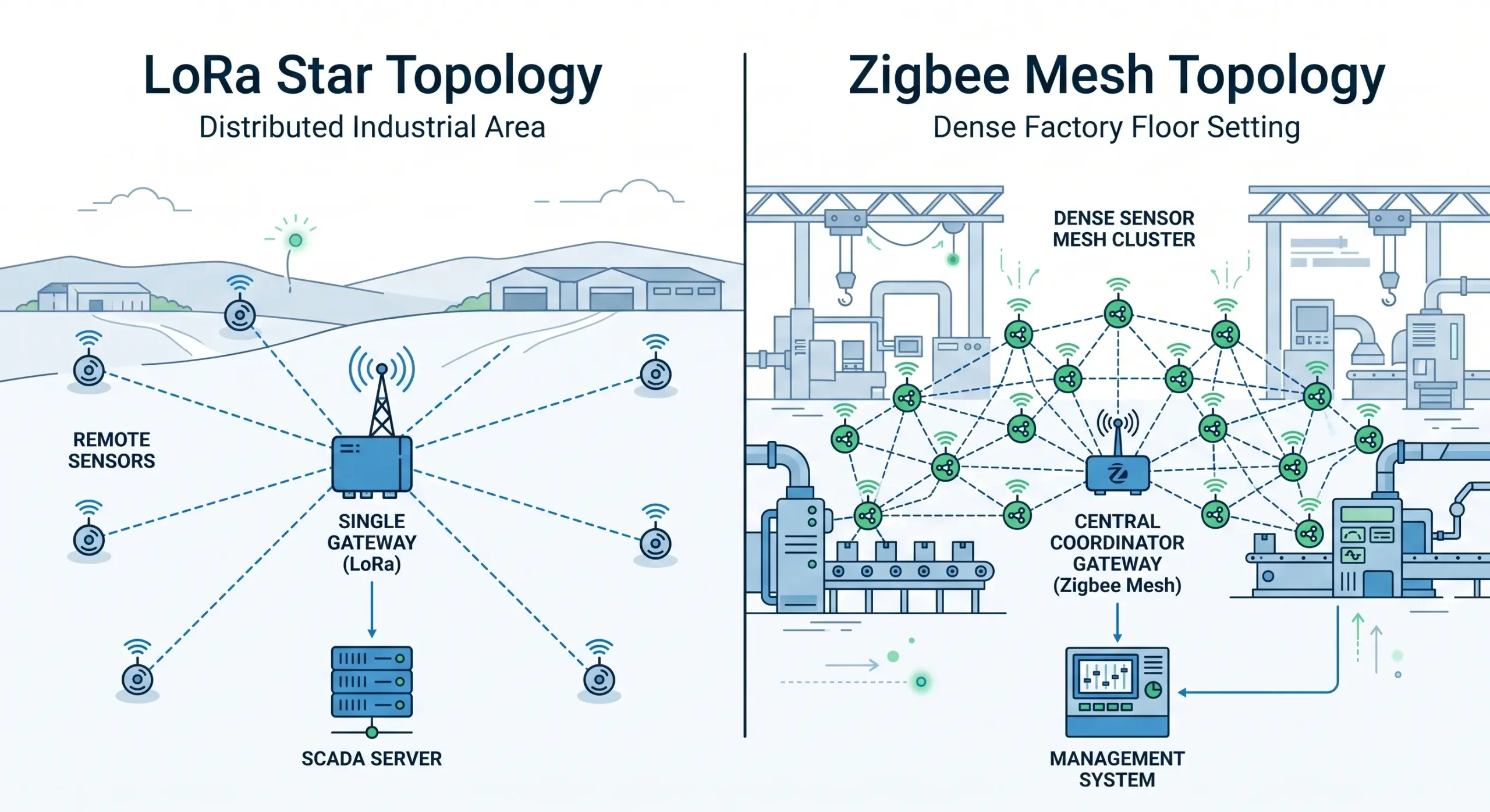 Figure 1: LoRa’s Star topology excels across vast distances, while Zigbee’s Mesh topology thrives in dense, localized environments.
2. Signal Penetration and Interference: 2.4GHz vs. Sub-GHz Physics
Radio frequency (RF) physics dictate network survivability in industrial environments. A protocol’s operating frequency directly determines its wavelength, which subsequently governs its ability to penetrate physical obstacles.
Industrial Zigbee conforms to the IEEE 802.15.4 standard, operating globally in the 2.4GHz ISM band (specifically 2.405GHz to 2.480GHz). Due to its short wavelength, 2.4GHz signals are highly susceptible to absorption and reflection by dense materials like reinforced concrete or thick steel enclosures. Furthermore, the 2.4GHz spectrum is notoriously crowded, sharing airwaves with factory Wi-Fi networks and Bluetooth peripherals.
Zigbee uses Direct Sequence Spread Spectrum (DSSS) modulation and CSMA-CA (Carrier-Sense Multiple Access with Collision Avoidance) to help alleviate this congestion. While these anti-collision mechanisms work very well with background electrical noise, Zigbee still has a fundamental need for a relatively clear physical path.
Conversely, LoRa utilizes Sub-GHz frequencies (such as 410MHz to 525MHz). Lower frequencies produce significantly longer wavelengths. A Sub-GHz LoRa signal can effectively diffract around heavy machinery and physically penetrate up to 5 floors of concrete in scenarios where a 2.4GHz signal would be completely eradicated.
Extensive independent evaluations, including peer-reviewed IEEE studies on industrial IoT physical layers, extensively document the superior propagation characteristics of Sub-GHz modulation. In dense urban and industrial settings, a Sub-GHz LoRa wave can easily diffract around heavy machinery and physically penetrate multiple concrete barriers in scenarios where a 2.4GHz signal would be completely eradicated.
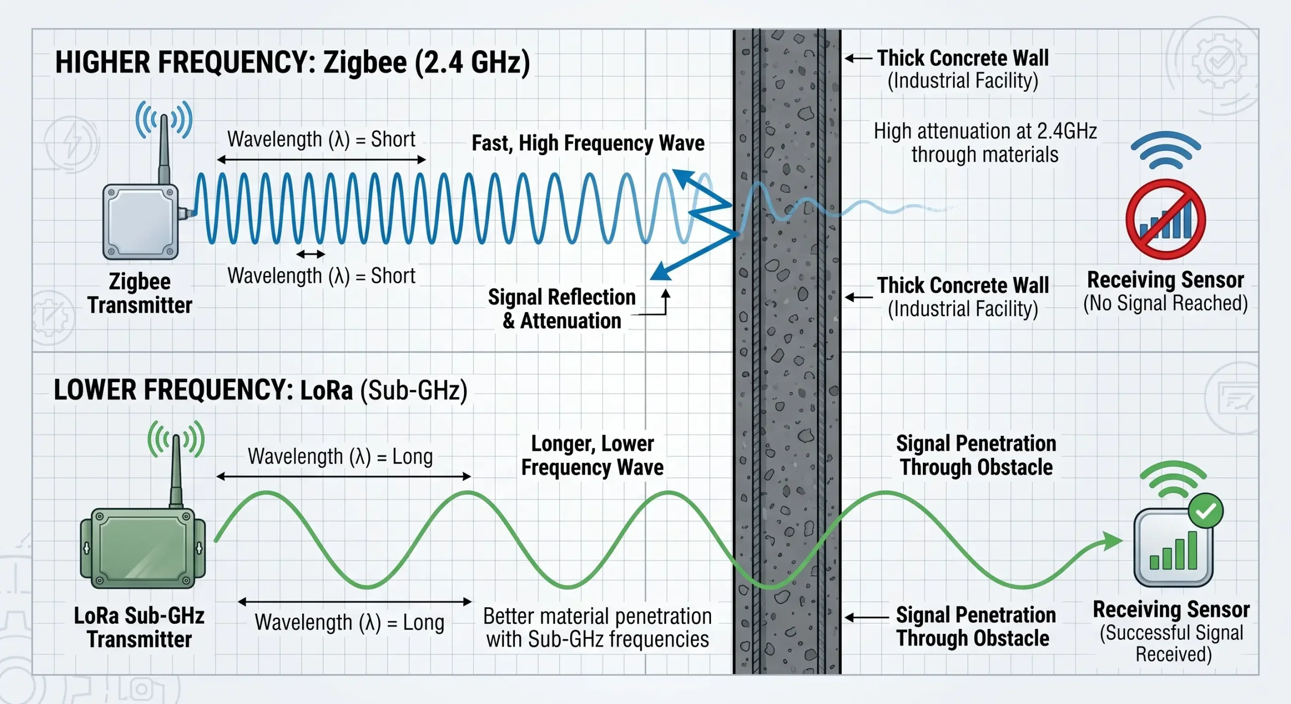 Figure 2: Sub-GHz frequencies possess inherently longer wavelengths, enabling them to penetrate concrete and steel obstacles that block higher-frequency signals.
Engineering Imperative: All protocols suffer from the same problem. Wireless nodes inside grounded steel control cabinets are surrounded by a Faraday cage and RF transmission suffers badly. Professional industrial equipment such as VT-LR600 and VT-ZIGBEE700 series, external antenna connectors (SMA male) are needed. This allows the technicians to route the antenna outside the steel enclosure, with magnetic bases, offering a clear line-of-sight.
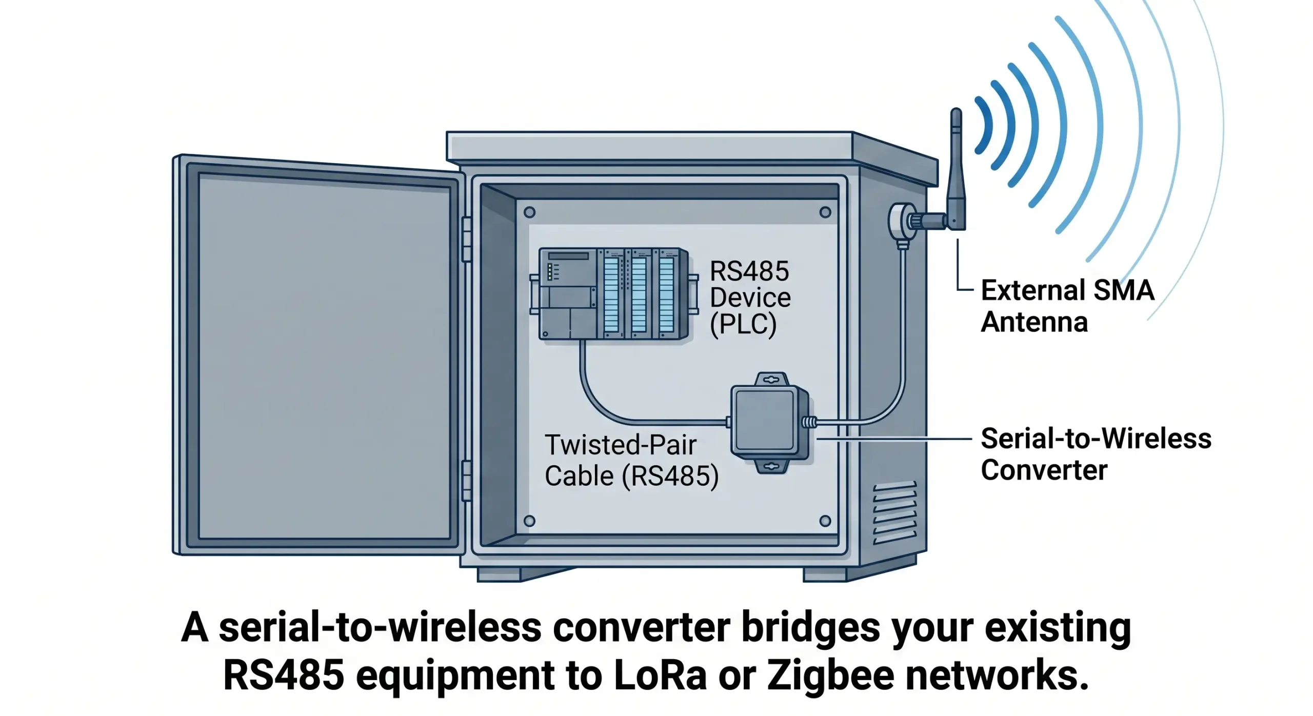 Figure 3: External SMA antennas are mandatory for industrial nodes mounted inside steel PLC cabinets to bypass the Faraday cage effect.
3. The Modbus Timeout Trap: Data Bandwidth vs. Latency
The most frequent error system integrators make when deploying wireless serial networks is treating RF transmission like hardwired gigabit Ethernet. All wireless serial networks are constrained by strict baud rates, packet sizes, and airtime limits.
Zigbee: High-Bandwidth Data Smoothness
If a master PLC is programd to poll 20 remote nodes every 500 milliseconds for operational status then Zigbee is the mandatory choice. Industrial Zigbee converters can provide reliable duplex data transmission at continuous serial data rates up to 38400bps without packet loss using their 2.4GHz bandwidth. The protocol’s Carrier-Sense Multiple Access (CSMA-CA) algorithm allows devices to quickly verify channel availability, transmit payload data (up to 100 bytes per frame) and receive acknowledgments immediately. This gives you a very low latency and perfect smoothness of data.
LoRa: The Airtime Cost of Extreme Distance
LoRa achieves its exceptional -140dBm receiver sensitivity by utilizing Chirp Spread Spectrum (CSS) modulation. The mathematical trade-off for this extreme distance is an exceedingly low data transmission rate and extended “Time on Air”.
Attempting to poll a LoRa network continuously every 100 milliseconds will result in immediate network failure. The long chirp lengths will cause packets to collide mid-air, the modems will queue the overlapping data, and the overarching SCADA software will trigger cascading “Modbus Timeout Errors.” Consequently, LoRa is strictly suited for exception-based reporting or intermittent telemetry—such as reading a remote energy meter or chemical tank level once every 5 minutes.
| Protocol | Frequency | Transmission Range | Optimal Data Payload / Rate |
|---|---|---|---|
| Zigbee (VT-700) | 2.405GHz ~ 2.480GHz | Up to 2,000 meters | Medium. Continuous flow up to 38400bps; 100-byte frames. |
| LoRa (VT-LR600) | 410MHz ~ 525MHz | 6 to 8 Kilometers | Low. Very small data packets; infrequent polling. |
| SCADA Polling Requirement | Protocol Verdict | Engineering Rationale |
|---|---|---|
| Deterministic Control (1ms – 10ms) | NEITHER | RF latency introduces severe jitter. Hardwired Ethernet (Profinet/EtherCAT) is absolutely required for safety/motion logic. |
| Continuous Polling (100ms – 2 seconds) | ZIGBEE | Zigbee’s wider bandwidth and CSMA-CA loop execute rapid, synchronous request/response cycles without queuing delays. |
| Intermittent Telemetry (Minutes to Hours) | LORA | Slow polling accommodates LoRa’s extended time-on-air, allowing operators to leverage its massive 8km range. |
4. Power Infrastructure: The DIN-Rail Reality
One of the worst mistakes in IoT marketing is to talk only about the “10-year battery life” of LoRaWAN sensors. This story doesn’t work for heavy industrial automation retrofits, but it’s true of tiny, dormant environmental pucks.
When interfacing legacy field equipment, wireless modems are installed in existing PLC cabinets or next to high power instrumentation (e.g., flow meters, motor contactors) that use continuous 24V DC panel power. So industrial modems don’t have replaceable coin-cell batteries.
Both VT-LR600 and VT-ZIGBEE700 series have terminal blocks that can accept a wide DC 9~24V input. They are designed to draw very little current so as not to overtax panel supplies. The VT-LR600 draws around 30mA@12V and the VT-ZIGBEE700 draws 50mA@9V.
The actual cost differentiator between the protocols is infrastructure wiring (Trenching).
For an integrator to use Zigbee over 3+ miles, they physically have to install intermediate routing nodes. That means pouring concrete pads, erecting poles, trenching conduit to get 24V power to nodes that exist only to bounce the signal. LoRa communication is preferred for long distances because it transmits the signal from source to destination in a single hop. Where LoRa really saves you huge CapEx is in totally eliminating intermediate power trenching.
5. Bridging the IT/OT Gap: Modbus TCP to RTU Gateways
Connecting RS485 equipment is only half the battle. Modern SCADA software, historians, and cloud dashboards communicate exclusively via Ethernet (TCP/IP). Raw serial radios cannot natively interface with IT networks. This requires a dedicated network Gateway.
Industrial gateways—such as the VT-ZIGBEE701 and VT-LR601—serve as multi-function network translators. Field nodes transmit serial data over the RF medium. The central gateway receives the RF payload and converts it directly into TCP/IP packets via its standard RJ45 Ethernet port.
Native Modbus Protocol Conversion
To streamline PLC integration, these gateways feature onboard Modbus conversion. Accessing the gateway’s web configuration (typically via IP 192.168.1.200 or 192.168.1.254), engineers can set the internal “Transfer Protocol” to Modbus TCP <-> RTU.
The Master PLC polls the Ethernet gateway at its IP address on Port 502 using standard Modbus TCP in this architecture. The gateway transparently intercepts the TCP request, translates it to a Modbus RTU format, broadcasts it on the Zigbee or LoRa network to the target slave node, waits for the RTU response, translates it back into a Modbus TCP and returns it to the PLC. The SCADA system is not aware of the wireless serial conversion at the edge.
Legacy HMI Support via Virtual Serial Ports
Facilities running legacy SCADA software that requires physical COM ports (e.g., COM3) can utilize virtual port mapping. Tools like Vircom can be installed on the Windows server to bind a newly created virtual COM port directly to the gateway’s IP address. When the legacy software opens the virtual COM port, the data routes seamlessly across the LAN to the gateway, and out across the wireless network to the field devices.
| Network Mode | Industrial Functionality |
|---|---|
| TCP Server | Passive operation. The gateway listens on a specified port (e.g., 4196) and waits for the central PLC or SCADA software to actively initiate the TCP connection. |
| TCP Client | Active operation. The gateway is programmed with a Destination IP and Port. Upon booting, it actively pushes data to the remote server or cloud database. |
| UDP Mode | Connectionless broadcasting. The gateway transmits data packets to the network without requiring a handshake, ideal for fast, non-critical telemetry streams. |
| JSON + MQTT | Direct IoT Cloud integration. (Available natively on devices like VT-LR601 to automatically poll Modbus/645 instruments and push formatted JSON to the cloud). |
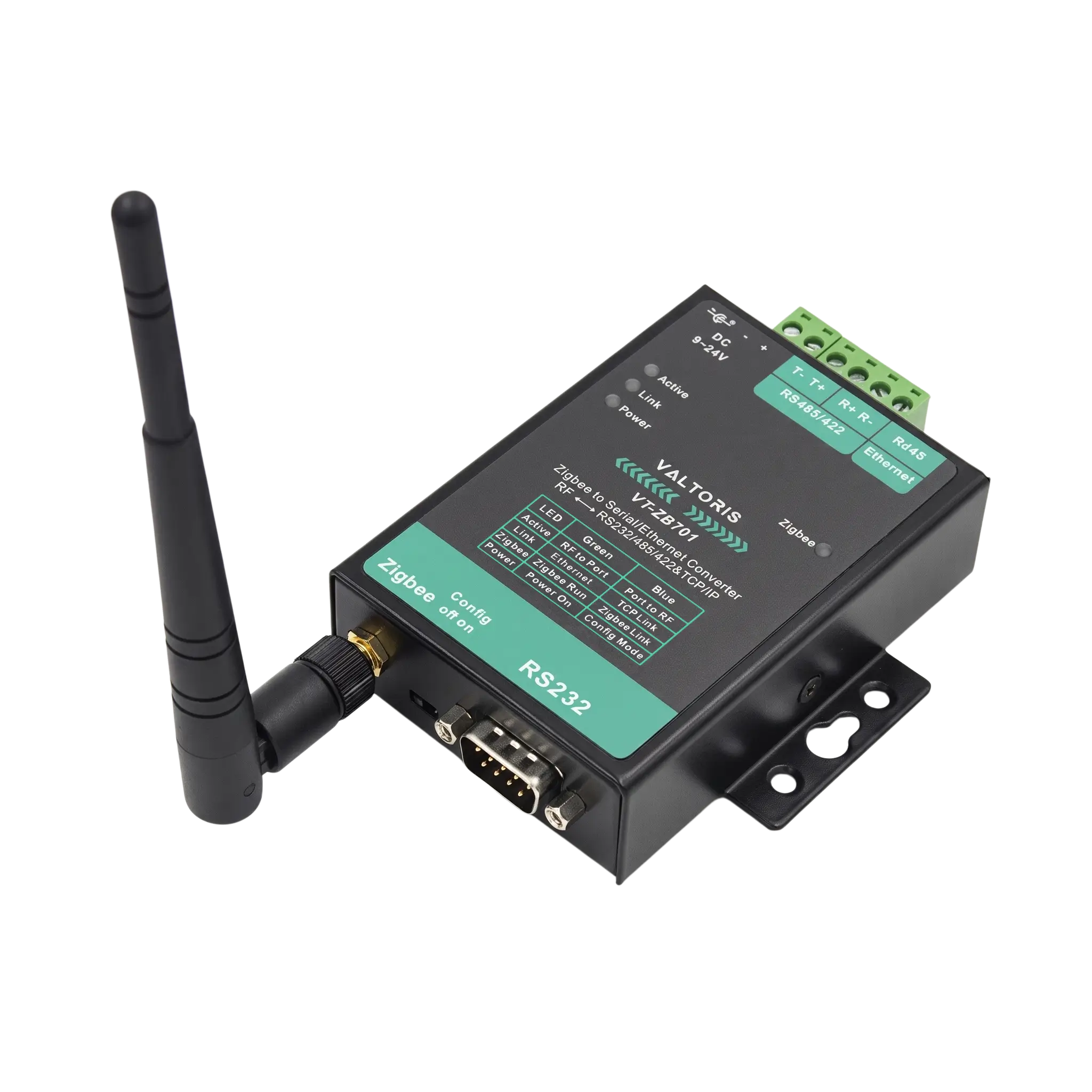 Figure 5: The VT-ZIGBEE701 Gateway. Ethernet-enabled gateways are the critical linchpin for passing serial RF data directly into modern TCP/IP networks.
OT Cybersecurity: Encryption at the Edge
While bridging the IT/OT gap solves connectivity issues, it introduces potential security vulnerabilities if raw OT data is broadcast over open airwaves. To mitigate interception by rogue industrial sniffers, professional industrial protocols natively support robust encryption frameworks (such as AES-128). This ensures your critical Modbus telemetry remains completely unreadable to unauthorized devices while traversing the wireless medium.
Field Deployment: Configuration & Diagnostics
Designing a network on paper is one thing; commissioning it on a dark factory floor is another. Industrial gateways must reduce the friction of installation.
Zero-Friction Configuration: Neither the VT-LR601 or VT-ZIGBEE701 gateway requires complex command line programming. Engineers simply plug the gateway into their LAN and use the default IP (192.168.1.200) to access the built-in Web GUI to configure baud rates, Modbus conversion, and destination servers. For bulk deployments, the dedicated Vircom management tool enables technicians to scan and configure multiple nodes simultaneously on the network, even across different subnets.
Visual Hardware Diagnostics: Downtime due to troubleshooting “invisible” RF networks. Valtoris industrial converters have diagnostic LEDs that are highly visible so you can isolate faults instantly without a multimeter. The ACT indicator flashes green when receiving data from the wireless network and flashes blue when transmitting data from the serial/Ethernet port. This allows our maintenance crews to quickly determine if a Modbus polling failure is caused by a dead sensor, a cut RS485 cable or a blocked RF signal.
6. Decision Matrix: Selecting Your Wireless Architecture
Selecting the optimal wireless protocol is an objective calculation based on distance, density, and data speed. Utilize this final matrix to architect your deployment:
| Existing Site Conditions | LoRa Approach (VT-LR Series) | Zigbee Approach (VT-ZIGBEE Series) |
|---|---|---|
| Geography: Devices are spread over miles (e.g., farms, pipelines). | Optimal. Deploy VT-LR600s + VT-LR601 Gateway. | Unviable. Range is too short; requires excessive routers. |
| Density: High concentration of devices inside a single building. | Viable, but extreme range capabilities are wasted. | Optimal. Deploy VT-ZB700s + VT-ZB701 Gateway. |
| Polling Speed: Frequent SCADA updates required (seconds). | High Risk. Data rate limits and CSS collision. | Optimal. Fast 2.4GHz duplex handling. |
| Environment: Heavy concrete bunkers, basements, thick steel. | Optimal. Sub-GHz penetration. | High Risk. 2.4GHz reflection and absorption. |
| Power / Specs: Harsh outdoor temperatures, 24V DC panel power available. | Supported. Metal case, -40°C to 85°C, 9-24V DC. | Supported. Metal case, -40°C to 85°C, 9-24V DC. |
Ultimately, there is no universal “best” protocol. A highly optimized facility may utilize both technologies simultaneously: a dense Zigbee mesh inside the primary manufacturing plant for fast machine monitoring, running in parallel with a long-range LoRa network reaching out to monitor distant utility meters. Because both lines feature Ethernet gateways, all data arrives cleanly at the same SCADA server via standard TCP/IP.
Evaluate your geographical layout, calculate your required polling frequencies, and deploy the architecture that natively respects those physical boundaries.
Frequently Asked Questions: Field Configuration & Troubleshooting
Can I use Modbus TCP directly over a LoRa network?
Yes, with a protocol conversion gateway. The edge LoRa nodes (VT-LR600) connect to your field sensors over RS485 (Modbus RTU). Your SCADA network is connected to the central LoRa Gateway (VT-LR601) thru the Ethernet. After logging in to the gateway and setting the transfer protocol to “Modbus TCP <-> RTU” the SCADA system can send standard Modbus TCP polling commands to the IP address of the gateway. The gateway translates the packet to RTU automatically, transmits it over LoRa and translates the response back to TCP.
How do I prevent my SCADA system from generating Timeout Errors when polling wireless nodes?
During retrofits, Modbus Timeout Errors are common as wireless transmission by nature has RF latency versus instantaneous copper wire transmission. With LoRa this latency is very important due to the long time-on-air. The fix for this is to go into your SCADA software or Master PLC programming and set the Modbus polling timeout duration to be much longer, many times to 1000ms, 2000ms or more to account for the wireless round trip delay.
Does an industrial 2.4GHz Zigbee network interfere with my plant’s Wi-Fi?
Industrial Zigbee uses the same spectrum as standard Wi-Fi, which is the 2.405GHz to 2.480GHz range. But Zigbee uses DSSS (Direct Sequence Spread Spectrum) and CSMA-CA anti-collision mechanisms to inherently reject noise. Engineers need to configure their Zigbee gateways manually to broadcast on specific IEEE 802.15.4 channels (e.g., 15, 20, 25 or 26) to enable clean data transfer. These particular frequencies are well tucked away in the “valleys” between the congested Wi-Fi channels (1, 6 and 11).
What is the difference between Transparent Point-to-Multipoint LoRa and LoRaWAN?
LoRaWAN is an overarching network architecture that requires external telecom Network Servers (LNS), complex device joining procedures, and often incurs monthly data fees. Transparent Point-to-Multipoint LoRa (such as the VT-LR600 series) strips away the cloud overhead. It utilizes raw LoRa radio modulation to create a private, localized serial bridge between your own hardware. Once powered on and matched in frequency and baud rate, data transmits directly between your nodes with zero internet dependency and zero recurring costs.
Can I power these wireless converters directly from the 24VDC supply inside my PLC cabinet?
Absolutely. Professional industrial wireless converters are engineered explicitly for control panel integration. Both the Valtoris VT-LR and VT-ZIGBEE series accept wide-voltage 9-24V DC inputs via standard industrial terminal blocks. Their power consumption is highly optimized; for instance, the VT-LR600 draws just 30mA@12V, and the VT-ZIGBEE700 draws 50mA@9V. They will safely operate off your existing 24VDC instrument power supplies without inducing voltage drops.
Stop Guessing. Start Transmitting.
Do not let legacy wiring limit your facility’s data visibility. Whether you need the 8-kilometer penetration of Sub-GHz LoRa or the high-speed dense routing of a Zigbee Mesh, deploying true industrial-grade protocol converters ensures your Modbus networks stay online.
Request a Network Architecture Review