

Modbus RTU to TCP Gateway: Setup & Timeout Troubleshooting
A modbus timeout error is arguably the most common and frustrating hurdle in industrial automation. While it can occur on any native serial or Ethernet network, it becomes notoriously difficult to diagnose when you are bridging legacy RS485 devices to a modern SCADA system.
If you’ve wired the terminals and pinged the IP successfully, but data still won’t flow, the issue usually lies in the protocol translation. A Modbus RTU to TCP gateway is not a transparent cable—it’s an active CPU. Standard quick-start manuals are useless when you receive dropped packets or Exception 0x0B. The only way to fix these timeouts once and for all is to verify your system layer by layer.
This definitive setup and troubleshooting guide takes you through the exact physical checks, network configurations, routing rules, and timing calculations you need to correctly commission your gateway and eliminate timeouts for good.
⚡ Quick Troubleshooting Navigation:
- 1. The Physical Layer: RS485 Wiring & Termination Resistors
- 2. Network Layer: Static IP & Subnet Isolation
- 3. Serial Layer: Baud Rate & Parity Mismatches
- 4. Translation Layer: Slave ID Routing & Mapping
- 5. Timing Issues: Polling Rates & Response Timeouts
- 6. Multi-Master Setup: Handling Multiple TCP Clients
- 7. Decoding Modbus Exception Codes & LED Diagnostics
1. The Physical Layer: Correct RS485 Wiring and Termination
A gateway cannot translate what it cannot physically hear. If your SCADA returns an Exception 0x0B (Target Device Failed to Respond), there is a 90% chance the issue is not in your TCP/IP settings, but down on the raw copper wire.
Before diving into TCP subnets and Modbus routing, ensure your serial bus complies with strict EIA-485 physics. Common silent killers that destroy Modbus frames include:
- A/B Polarity Reversed: Different vendors swap the (+) and (-) labels, causing inverted logic.
- Missing 120Ω Termination: Signal reflections on lines over 200m destroying the square waves.
- Star Topology: RS485 strictly requires a linear daisy-chain.
- Floating Grounds: Missing the 3rd Signal Ground wire, causing common-mode voltage failures.
| Cable Type | Shielding | Twisted Pair | Suitability for Modbus RS485 |
|---|---|---|---|
| RVV (Standard Power Cable) | None | No | ❌ Will cause data corruption and timeouts in industrial environments. |
| Cat5e / Cat6 (Ethernet) | Optional | Yes | ⚠️ Acceptable for short runs, but wire gauge (AWG 24) is often too thin for long RS485 networks. |
| RVSP / STP (Shielded Twisted Pair) | Yes (Foil/Braid) | Yes | ✅ The Industry Standard. Essential for noise immunity. |
If you are unsure about your cable physics, stop configuring the gateway and read our comprehensive Ultimate RS485 Wiring & Topology Guide to eliminate Layer 1 faults first.
2. Network Configuration: Setting Static IP and Subnet Masks
Once the serial cables are secured, you must integrate the gateway into the local IT infrastructure. By default, many gateways ship with DHCP enabled, meaning they will automatically request an IP address from the network router.
For consumer electronics DHCP works well. For industrial OT infrastructure, it is a disaster waiting to happen. If the factory loses power and the router reboots, the gateway might be assigned a completely different IP address. The SCADA system, which is programmed to constantly query a specific IP, will suddenly go blind.
You must assign a Static IP Address to your gateway.
Configuration Steps:
- Connect your laptop directly to the gateway’s Ethernet port.
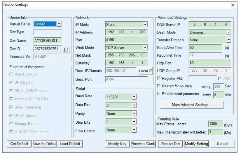
- You need to change the IPv4 settings on your laptop so that it’s on the same network as the gateway. (The gateways default IP address is usually something like 192.168.1.254 or 192.168.0.7. )
- Log into the gateway’s web GUI via your browser.
- Navigate to the “Network Settings” or “LAN” tab.
- Change the IP allocation from DHCP to Static.
- Enter an IP address provided by your IT department—one that is strictly outside the network’s DHCP pool to prevent future IP conflicts.
- Ensure the Subnet Mask exactly matches your local network (usually
255.255.255.0). - If the SCADA system is located on a different network segment, ensure the Default Gateway IP is correctly pointing to your local router.
Engineer’s Note: save and reboot the gateway. Now open your computer’s command prompt and type ping [Gateway IP]. If you get consistent replies with no packet loss, your IT layer is good and you can proceed to the OT configuration.3. Matching Serial Parameters: Baud Rate, Parity, and Stop Bits
A Modbus gateway has a serial port configuration page that must perfectly mirror the settings of the downstream RTU slave devices. Modbus RTU is an asynchronous protocol. There is no seperate clock signal wire telling the receiver when a bit of data starts and ends; both the gateway and the slave devices rely on strict timing agreements.
If the SCADA software shows a timeout, check these three parameters immediately:
- Baud Rate: The speed of transmission (e.g., 9600, 19200, 38400, 115200).If the gateway is set to listen at 19200 but the temperature controller is sending information at 9600, then the gateway will only hear noise.
- Data Bits: Always set to 8 for Modbus RTU.
- Parity & Stop Bits: This is where 80% of configuration errors occur. Parity is a basic error-checking mechanism. You can choose Even, Odd, or None.
According to the official Modbus Organization Serial Line Specification, if Parity is set to None, the device must transmit 2 Stop Bits (also written as 8-N-2) to be able to maintain the character frame length. However, many low cost device manufacturers ignore this strict standard and default their devices to 8-N-1.
| Gateway Setting | End Device (Sensor) Setting | Result on SCADA |
|---|---|---|
| 8-E-1 (Even Parity) | 8-E-1 (Even Parity) | ✅ Perfect Communication |
| 8-N-1 (None, 1 Stop) | 8-N-2 (None, 2 Stop) | ⚠️ Intermittent errors. Missing the final stop bit causes frame shifting. |
| 8-E-1 (Even) | 8-N-1 (None) | ❌ 100% Timeout. Bits misaligned, RX light flashes but data is rejected. |
Consult the manual for your particular field device. Even with a slight mismatch, framing errors will occur. This is the hidden cost of simple converters. Modern protocol gateways (such as the Valtoris 1CH-ETH) feature Auto-Baud and Auto-Parity detection so they will lock on to the downstream device immediately, without tedious trial and error.
4. Modbus Protocol Translation: Slave ID Routing and Register Mapping
This is the central nervous system of the gateway and arguably the most confusing aspect for engineers transitioning from IT environments to industrial automation.
Modbus TCP (the Ethernet side) relies on IP addresses and TCP port 502 to locate a device on the vast Ethernet network. Modbus RTU (the serial side), however, relies on a physical daisy-chained wire and a Slave ID (a number from 1 to 247) to identify the specific device on that wire.
When your SCADA system sends a Modbus TCP request, the request header (known as the MBAP – Modbus Application Protocol header) contains a 1-byte field called the Unit Identifier. The gateway reads this incoming TCP packet, strips away the Ethernet and TCP wrappers, looks at the Unit Identifier, and converts it into the Slave ID for the RTU serial frame.
How to Configure Routing: For basic single-port gateways (like the 1CH-RS485-ETH), routing is usually automatic. The gateway simply takes the TCP payload and blasts it out of the single serial port, trusting that the device with the matching Slave ID on the RS485 bus will respond.
However, industrial architectures rarely consist of a single daisy chain. When aggregating multiple isolated serial buses—such as combining separate RS485 zones or integrating RS232 PLC ports under a single IP address—you must deploy a multi-port gateway like the Valtoris 4CH-RS232/485/422-ETH.
In these multi-port scenarios, blind broadcasting causes severe delays. You must explicitly define a routing table in the gateway’s firmware, dictating exactly which physical serial port handles which specific Slave IDs.
| TCP Port | Virtual ID Range (Unit Identifier) | Mapped Serial Port | Target Connected Devices |
|---|---|---|---|
| 502 | 1 – 10 | Serial Port 1 (RS485) | VFDs (Variable Frequency Drives) |
| 502 | 11 – 20 | Serial Port 2 (RS485) | Digital Power Meters |
| 502 | 21 – 30 | Serial Port 3 (RS232) | Legacy CNC Machine |
If a Modbus TCP client requests data for Slave ID 15, the gateway references this table and knows it should only send that RTU packet out of Serial Port 2. If this routing table is left blank or configured incorrectly, the gateway will not know where to physically send the electrical signals. The SCADA system will instantly receive a “Gateway Path Unavailable” exception.
5. Managing Polling Rates and Response Timeouts
The main cause of network congestion is the great discrepancy in bandwidth between high speed Ethernet (100Mbps/1Gbps) and legacy RS485 serial buses (typically 9600bps). When a modern SCADA system polls at high frequencies, the gateway must buffer and sequence these requests to match the physical limits of the serial line. If the polling interval is shorter than the serial transmission time, the gateway’s buffer will overflow, causing a dropped packet and an inevitable modbus message timeout.
If your SCADA system is aggressively polling a serial device for 100 holding registers every 50 milliseconds, you are creating a massive traffic jam at the gateway. The gateway receives the TCP requests instantly, but it has to wait for the slow serial line to push the bits out serially, and then wait for the slave device’s internal processor to formulate a reply.
To bridge this gap, you must adjust two critical timing settings:
1. Response Timeout: This tells the gateway how long to wait for an answer from the serial slave before giving up and returning an error code to the TCP client.
2. Inter-character / Inter-frame Delay: The Modbus RTU states that a minimum silent period of 3.5 character times shall be present on the bus to mark the end of a message frame. If the next request from the gateway is sent too quickly, the slave device will not be aware that the previous message has been completed and will ignore the new command.
To help visualize the physics of the serial line, refer to this benchmark table:
| Baud Rate (bps) | Time to Transmit 1 Character (11 bits) | Minimum Inter-frame Delay (3.5 chars) | Recommended SCADA Timeout Setting |
|---|---|---|---|
| 9600 | ~1.15 ms | > 4.0 ms | 500 ms – 1000 ms |
| 19200 | ~0.57 ms | > 2.0 ms | 300 ms – 800 ms |
| 115200 | ~0.09 ms | > 1.75 ms (fixed) | 100 ms – 500 ms |
If you leave the timeout at a default of 50ms on a 9600 bps network, the gateway will abort the transaction before the serial device even finishes transmitting its answer. Slow down your SCADA polling rate to match the physics of your serial bus. More data does not always mean faster polling; it often means optimizing your register reads into a single block request.
🚀 The Ultimate Fix: Using an Active “Storage Modbus Gateway”
To completely eliminate protocol timeouts caused by TCP jitter, you must move away from generic transparent passthrough converters. You need what the industry calls a Storage Modbus Gateway.
The entire Valtoris Modbus Gateway Family (from 1CH up to 32CH rack-mounts) features an integrated polling cache. These devices proactively poll your RS485 slave devices and temporarily save the register data inside their internal memory. When your SCADA issues a TCP query, the gateway responds instantly (typically within 3ms). This completely decouples the fast TCP network from the slow RS485 bus, eliminating timeout exceptions entirely.
6. Multi-Master Setup: Handling Multiple Modbus TCP Clients
If you’ve checked all the physical wiring and the timing settings, and you’re still getting intermittent timeouts during peak operation, you may have a hidden multi-master collision.
A very typical industrial situation is a central SCADA system in the control room and a local HMI touchscreen on the factory floor. Inevitably the client wants both of these systems to be able to pull data from the same downstream RS485 devices at the same time.
The problem with the architecture is that RS485 is a half duplex bus. Only one device can speak physically at a time. Now what if the requests of the SCADA system and the local HMI are sent to the gateway at the same millisecond? How does the gateway avoid a data collision on the serial wire?
Cheap, basic converters don’t cut it here. They just try to send both requests to the serial port at the same time, which leads to corrupted frames and dropped connections all the time.
How it works:
- Protocol Arbitration: The gateway allows multiple IP addresses and multiple asynchronous TCP connections. It does not drop packets.
- Deterministic Queuing: When Master A (SCADA) and Master B (HMI) transmit simultaneously, the gateway grants immediate physical access to the RS485 wire to Master A under the priority scheme and caches the request of Master B in a dedicated internal FIFO memory buffer.
- Sequential Execution: Wait for the RTU answer to Master A, translate to TCP and deliver. Just after it dequeues Master B’s request, executes the serial query and sends the response back to the HMI – no data collisions on the half-duplex wire.
When setting up multi-master networks, it is crucial to extend the TCP timeout settings in your SCADA and HMI software. Because the gateway is forcing requests to wait in line, the apparent response time for the SCADA system will naturally increase as more masters are added to the network.
Deep Dive: Advanced Architecture
If your project requires scaling beyond two masters, or you are experiencing persistent 0x0B exceptions during simultaneous HMI/SCADA polling, the physical RS485 data collision needs advanced arbitration.
Read our engineering guide on Solving RS485 Data Collisions in Multi-Master Networks →
7. Testing and Troubleshooting Your Gateway Connection
You wired the terminals, set an IP address, matched the baud rate, defined the routing. But the dashboard still reads “No Comm. If the gateway is acting like a black box you need to follow a methodical troubleshooting process to determine if the problem is on the Ethernet side or the serial side.
Step 1: Check the Gateway Diagnostics LEDs (e.g., 1CH-RS485-ETH)
Using the Valtoris 1CH-RS485-ETH as an example, the physical LEDs are your fastest diagnostic tool. It features three specific lights: PWR, LINK, and ACT.
| LED Indicator | Normal State | Fault Indication & Meaning |
|---|---|---|
| PWR (Power) | Solid Green | Off: Check 9~24V DC terminal wiring or power supply polarity. |
| LINK (TCP Status) | Solid Blue | Solid Green: Network is plugged in, but SCADA has not established a TCP connection (IP/Port mismatch). |
| ACT (Data Flow) | Flashes Green & Blue | Only Flashes Green: SCADA requests are arriving, but the RS485 slave is dead, wired backward, or ignoring the baud rate. |
Step 2: Remove the SCADA System from the Equation
SCADA systems have complex background services that can mask root causes. To diagnose raw connectivity, use a dedicated diagnostic tool. We highly recommend downloading a trial of Modbus Poll, the industry-standard simulator software.
Install it on your laptop, connect to the same network as the gateway, and try to read a known holding register (like 40001). If you immediately encounter a modbus poll timeout error here, you have isolated the fault: the issue is on the hardware gateway or the physical RS485 wire, not your SCADA tag configuration.
Step 3: Analyze Exception Codes
If the gateway successfully communicates with the RTU device but something is logically wrong, the protocol will return an Exception Code rather than raw data. Understanding these codes saves hours of guesswork:
When you configure a gateway from Modbus RTU to TCP, there are hardware and protocol details to consider. Go through your RS485 termination systematically, fix a static IP, match the serial framing parameters to the letter, and respect the polling speed limits of legacy busses, and you can get an OT network bridge that runs continuously without a single dropped packet. One step at a time. Separating the variables. And always pay attention to the guidance of your gateway’s LINK and ACT diagnostic LEDs.
Are you using a specific SCADA platform? If you need a step-by-step software configuration walkthrough, check out our [👉 Complete Modbus TCP Setup Guide for MCGS SCADA].
Frequently Asked Questions
I enabled the 120-ohm termination resistor as suggested, but now my communication drops completely. Why?
Why does my gateway work fine for a few hours, but then randomly timeouts until I reboot it?
I get a timeout error on SCADA, but the ACT light on the gateway is definitely flashing blue. What’s wrong?
My SCADA connects to the gateway’s IP, but I get a “Protocol Error” or instant disconnect. What’s wrong?
What if I need to collect local sensor data at the gateway location alongside bridging my RS485 devices?
Should my Modbus gateway be configured as a TCP Server or TCP Client?
SCHEDULE A TOPOLOGY DIAGNOSIS
Still dropping packets after tuning your baud rates and adding termination resistors? The issue might be severe EMI noise or a TCP framing conflict. Describe your SCADA and field device setup below, and our networking engineers will help you isolate the fault.
