
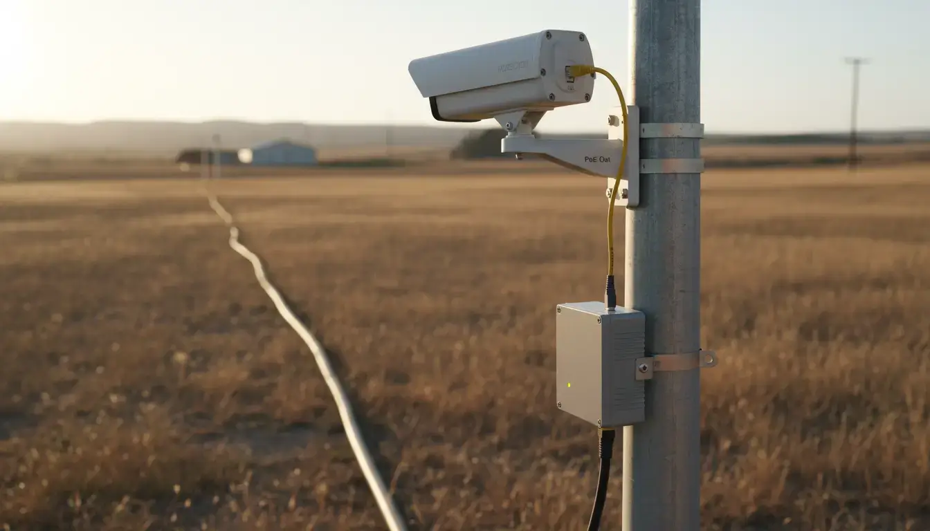
Network engineering operates within the absolute, mathematical boundaries of physical laws. For traditional copper Ethernet (Category 5e or Cat6), that boundary is exactly 100 meters (328 feet). Attempting to push high-frequency electrical signals beyond this specific distance results in severe signal attenuation, cross-talk, packet collisions, and inevitable link failure. This is not a manufacturer’s cautious suggestion; it is a rigid physical limitation strictly defined by the IEEE 802.3 Ethernet working group.
However, modern infrastructure is expanding. When sprawling industrial facilities, expansive university campuses, distributed agricultural sites, or high-voltage power substations need to route telemetry data far beyond that 100-meter wall, they must transition from electrical signals to optical light.
It is not economically feasible or operationally disruptive to replace every existing copper-based network switch, programmable logic controller (PLC) or IP surveillance camera with native optical hardware. A dedicated bridging technology is required for this physical bottleneck. Residential end users are familiar with the home internet termination boxes as “fiber optic modems” (more correctly Optical Network Terminals or ONTs), but industrial network engineers use an entirely different, ruggedized architecture: the fiber media converter.
This comprehensive engineering guide will break down precisely what a fiber media converter is, how to convert standard Ethernet and legacy RS485 serial data into light, the critical differences between consumer plastics and industrial-grade enclosures, and the fastest data transfer technologies shaping industrial networks in 2026.
Table of Contents
- The 100-Meter Wall: What Is a Fiber Media Converter?
- Breaking Limits: How to Convert Ethernet & RS485 to Fiber
- Beyond Consumer IT: What Makes a Media Converter “Industrial”?
- Optical Interface Standards (SC vs. LC/ST)
- Single-Fiber vs. Dual-Fiber: Cutting Copper Costs by 50%
- IT/OT Convergence: Virtual Serial Ports & TCP/IP Routing
- 2026 Data Transfer Technologies: When to Upgrade to a Switch?
- Designing the Network: The Hardware Pair-Connection Guide
- Troubleshooting the “Link Down” Nightmare: Diagnostic LEDs
- Frequently Asked Questions
The 100-Meter Wall: What Is a Fiber Media Converter?
At its core, a fiber media converter is a localized networking bridge that translates physical layer signals. It accepts standard electrical data packets from a copper interface (such as an RJ45 Ethernet port or an RS485 terminal block), modulates those electrical voltage variations into a stream of microscopic light pulses, and transmits them across a glass fiber optic cable.
At the destination point, a paired converter reverses this exact process, turning the light photons back into an identical electrical signal. This entire translation process happens flawlessly at Layer 1 (the Physical Layer) of the OSI networking model.
Because the conversion happens at the physical layer, the end-point devices—whether they are two remote switches exchanging TCP/IP traffic, or a master PLC communicating with a distant Modbus flow meter—remain completely unaware that their data was serialized, converted to photons, fired across 20 kilometers of glass, and reconstructed. To the connected hardware, it appears as a direct, localized copper connection.
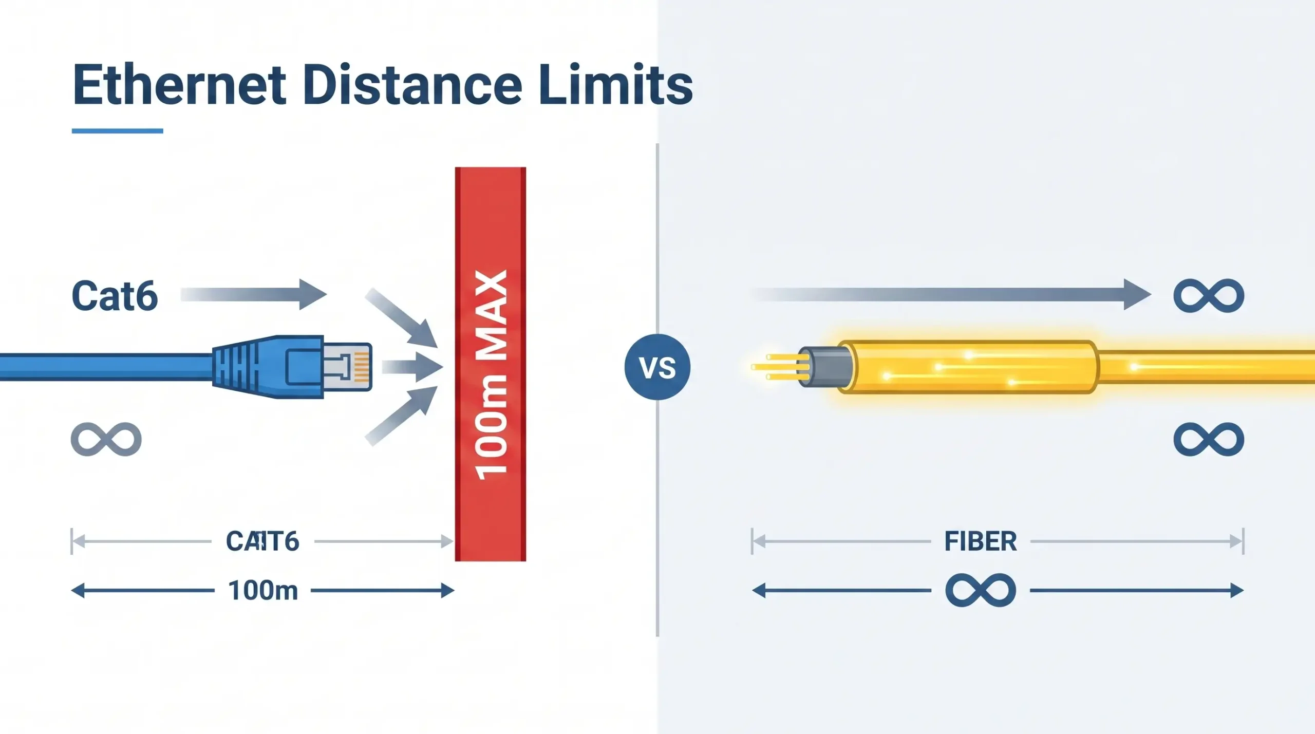 Figure 1: Copper Ethernet is physically constrained to 100 meters. Fiber media conversion is mandatory for campus-wide or cross-facility routing to bypass this limitation.
Doing this translation breaks the 100 meter copper limit . These converters . They enable standard RJ45 and RS232/485 devices to take advantage of the huge bandwidth, security and multi-kilometer reach of today’s fiber optics without massive hardware replacements.
| Network Medium | Maximum Reliable Distance | Immunity to EMI Noise |
|---|---|---|
| Copper Ethernet (Cat6) | 100 meters (328 ft) | Low (Requires heavy external shielding) |
| Serial RS485 (Twisted Pair) | 1,200 meters (Under ideal, noise-free conditions) | Moderate (Relies on differential signaling) |
| Multi-Mode Optical Fiber | Up to 2 kilometers | Absolute (100% dielectric immunity) |
| Single-Mode Optical Fiber | 20 km to 120+ kilometers | Absolute (100% dielectric immunity) |
Breaking Limits: How to Convert Ethernet & RS485 to Fiber Optic
While upgrading an IP camera or an Ethernet switch to a fiber backbone is the most universally recognized use case, deep industrial environments present a distinct, harder challenge: legacy serial data. Across global manufacturing, thousands of mission-critical Variable Frequency Drives (VFDs), remote flow meters, CNC controllers, and power relays still communicate exclusively via older RS232, RS485, or RS422 protocols.
According to extensive studies by the International Society of Automation (ISA), ambient industrial electromagnetic interference (EMI) is the leading cause of serial network failure. When a massive induction motor engages, the resulting magnetic spike can instantly induce stray voltage on nearby copper RS485 twisted-pair cables. This induced voltage scrambles the delicate Modbus data frames into unrecognizable garbage, causing the SCADA system to trigger cascading alarm failures.
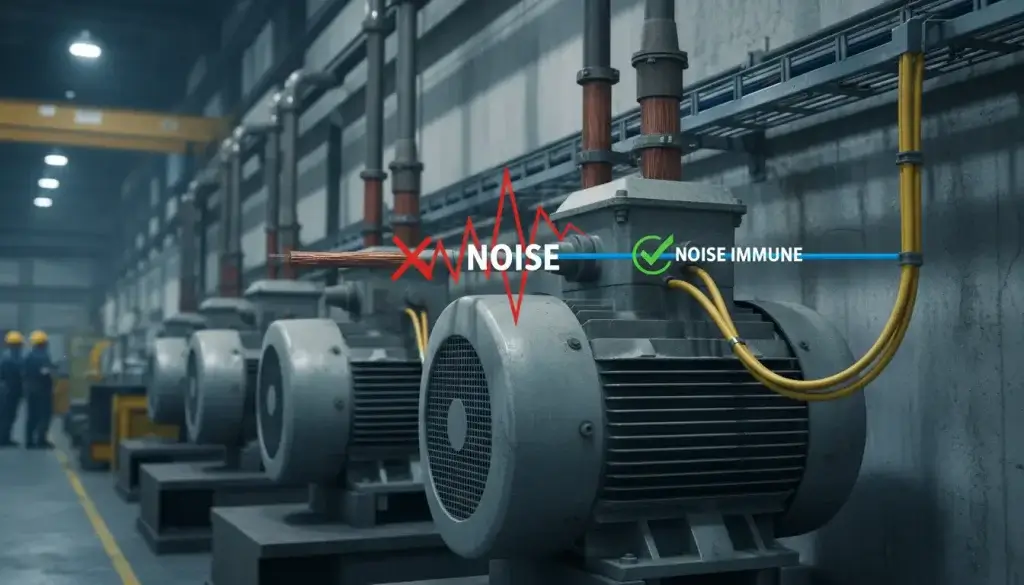 Figure 2: Heavy electromagnetic interference (EMI) from industrial VFDs and large induction motors will severely corrupt twisted-pair RS485 data. Fiber provides absolute dielectric isolation.
To definitively eliminate this threat, engineers convert the serial signal to light. Because optical fiber is constructed of dielectric glass, it is governed exclusively by the laws of optics, not electromagnetism. It is physically impossible for a magnetic field or a massive ground-loop voltage spike to interfere with a stream of photons.
The Hardware Benefit of “Zero-Delay” One of the common and well-founded fears of OT engineers is that adding a conversion device into a serial network will introduce processing latency that will cause “Timeout Errors” in strict Modbus RTU polling cycles.
High-end industrial serial-to-fiber converters (such as the VT-FB820 series) avoid this fatal flaw by using pure serial hardware decoding. Instead of waiting to fill a buffer with an entire 8-bit data frame before conversion, the hardware converts and sends the signal bit-by-bit over the fiber in absolute real-time. This zero delay mechanism provides smooth synchronization and is ideal for high speed rotational training systems where millisecond timing is critical.
To ensure absolute stability, industrial engineers must align their procurement with strict physical limits:
- Media Converter vs. SFP Switch: When you are extending a single PLC or IP camera point-to-point, the most cost-effective, lowest-failure-rate solution is a fiber media converter. However, if you want to aggregate 4 or 8 cameras at one remote pole, don’t daisy-chain converters. You must upgrade to an Industrial Ethernet Switch with SFP uplinks.
- Baud Rate Limits: The maximum baud rate supported by the VT-FB810/820 serial converters is 115200bps. This works perfectly for 99% of the world’s Modbus RTU devices, but does not work for high-speed Profibus DP networks running at 12Mbps.
- Interface Exclusivity: To guarantee optical continuity in high-vibration control cabinets, these converters utilize a fixed SC optic interface. They do not support hot-swappable LC SFP modules. Ensure your fiber patch cords are SC-terminated.
Beyond Consumer IT: What Makes a Media Converter “Industrial”?
Procurement teams scouring the Internet for optical modems often encounter consumer-grade devices (ONTs) meant for residential broadband or air-conditioned office racks. Placing these lightweight plastic enclosures inside a factory control panel or an outdoor NEMA box is a sure-fire way to invite catastrophic network failure.
The difference between consumer IT gear and industrial network hardware isn’t just about what they can do—it is about whether they can survive. True industrial fiber converters are unapologetically over-engineered to withstand thermal extremes, volatile electrical grids, and physical abuse.
1. Thermal Tolerance: The Silent Killer
Consumer electronics are rated for 0°C to 40°C. In an industrial setting, a sealed electrical panel baking in the direct summer sun can easily exceed 60°C, while unheated remote pump stations in winter can drop below -20°C. Industrial-grade media converters are engineered with wide-temperature components (like specialized oscillators and industrial capacitors) guaranteeing flawless startup and continuous operation from -40°C to 85°C (-40°F to 185°F).
2. EMI Immunity: The Invisible Disruptor
Factory floors are electrically chaotic. Massive induction motors, Variable Frequency Drives (VFDs), and arc welders generate severe Electromagnetic Interference (EMI). During switching operations, ambient transient electromagnetic fields can instantly corrupt data on standard commercial gear. Industrial converters utilize Anti-radiation SECC Boards (electrogalvanized steel) acting as Faraday cages, meeting strict IEC 61000-4 standards for electrostatic discharge and voltage transients.
3. Electrical Isolation: Protecting the Investment
When connecting equipment across different buildings, ground potentials can differ significantly. Without proper isolation, this voltage tries to equalize through communication cables, frying ports and destroying expensive PLCs. Industrial converters provide 1500V to 3000V of dielectric isolation, physically severing the electrical path between the copper and fiber sides to eliminate ground loops entirely.
| Parameter | Standard Commercial IT Gear | Industrial Fiber Converter |
|---|---|---|
| Enclosure | Lightweight molded plastic. | Metal (SECC / IP30+) for heat dissipation and EMI shielding. |
| Power Input & Draw | Fragile 12V AC/DC wall adapter (barrel plug). | 9~24V DC Wide Voltage. Includes 2-wire terminal blocks. Documented low current draw (165mA to 357mA at 9V) for precise control panel power budgeting. |
| Mounting | Desktop placement or loose shelf stacking. | Integrated DIN-Rail compatibility for vibration-proof control cabinet lock-in. |
| Lifespan (MTBF) | 2-5 years (50,000 hours). | 10-15+ years (>200,000 hours) designed for continuous operation. |
If the installation is outdoors, inside a metal electrical cabinet, near heavy motors/VFDs, or connecting two separate buildings, you absolutely need an industrial-grade converter. If it sits on a climate-controlled desk for a non-critical link, consumer-grade is fine.
Optical Interface Standards (SC vs. LC/ST)
Engineers selecting media converters must select the appropriate physical connector to mate with their fiber patch cables. The SC (Subscriber Connector) standard is preferred in industrial environments, while modern high-density data centers often opt for the miniaturized LC connector .
| Connector Type | Visual Profile | Industrial Viability & Usage |
|---|---|---|
| SC (Subscriber Connector) | Square, push-pull snap mechanism. | Highly Recommended. The square footprint and push-pull locking mechanism provide an incredibly secure, vibration-resistant connection. The larger ferrule is easier to clean and handle with gloved hands in harsh environments. Standard on devices like the VT-FB800 and VT-FB810. |
| LC (Lucent Connector) | Small, rectangular with a top retaining latch. | Good for high-density server racks (like SFP modules), but the delicate plastic retaining latch is prone to snapping off in rugged industrial panels. |
| ST (Straight Tip) | Round, metal bayonet twist-lock. | A legacy standard. Extremely secure due to the twist-lock, but largely phased out of modern converters due to the space required to twist the connector during installation. |
- Fiber Cable Specifications: If you buy single mode converters, like the VT-FB800/810/820, you need to combine these with standard 9/125μm OS2 Single-Mode patch cables. Single-mode optics over multi-mode (OM3/OM4) cables will result in severe signal degradation.
- 100M vs. Gigabit Bandwidth: The VT-FB800 is a very economical choice, as standard industrial telemetry and basic IP cameras will only require 10/100Base-TX speeds. However, if you are backhauling high density 4K video surveillance networks, you will need to upgrade your specification to Gigabit (1000Base-T) media converters to avoid network bottlenecks.
Single-Fiber vs. Dual-Fiber: Cutting Copper Costs by 50%
Historically, optical network links strictly required a “dual-fiber” architecture. Much like a divided multi-lane highway, one distinct glass strand was dedicated entirely to transmitting data (TX), while a second parallel strand was dedicated solely to receiving data (RX).
For systems integrators running cables across a sprawling 20-kilometer facility or municipality, paying for and pulling dual-strand fiber drastically inflated CapEx budgets. Furthermore, if existing underground conduits were full, adding a second line was physically impossible. The modern engineering solution to this constraint is BiDi (Bidirectional) Single-Mode Single-Fiber technology.
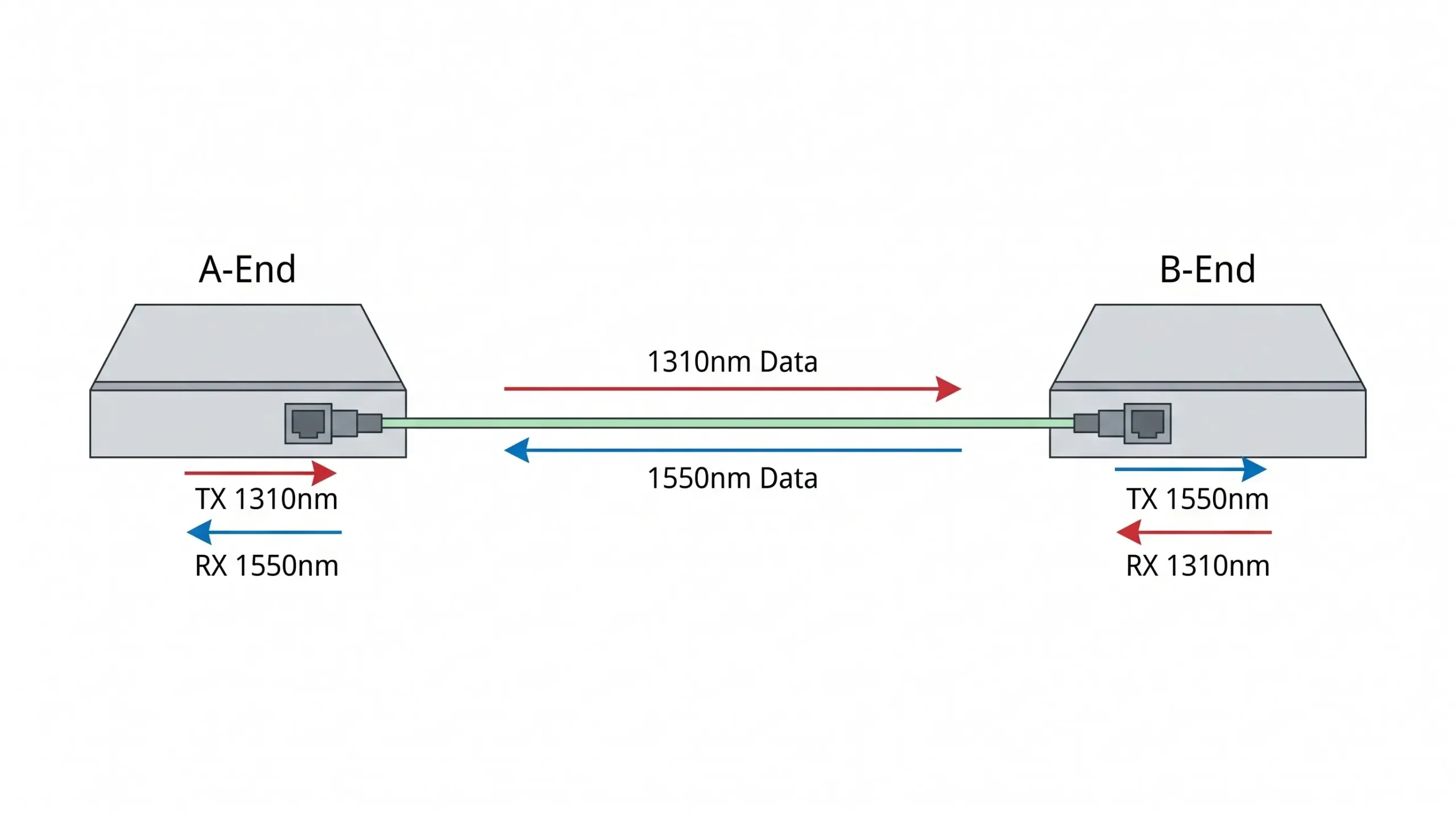 Figure 3: WDM BiDi technology utilizes two distinct wavelengths (1310nm and 1550nm) to achieve full-duplex communication over a single fiber strand. This single-fiber architecture cuts physical cabling costs in half.
BiDi technology utilizes Wavelength Division Multiplexing (WDM) to pass data in both directions simultaneously over one single strand of microscopic glass without collision. It achieves this physics-defying feat by assigning a different “color” (wavelength) of light to each direction.
Because the light travels in two distinct channels within the same tube, the hardware at each end of the fiber must be optically mismatched to complete the circuit. This introduces the critical concept of A-End and B-End pairing:
| Hardware Sub-Model | Emission (TX) Wavelength | Receiving (RX) Wavelength |
|---|---|---|
| A-End Converter (e.g., VT-FB800-A) | Transmits laser at 1310nm | Listens for laser at 1550nm |
| B-End Converter (e.g., VT-FB800-B) | Transmits laser at 1550nm | Listens for laser at 1310nm |
By enforcing this precise A/B pairing strategy across product lines, engineers cut the required physical fiber cabling footprint by exactly 50%, vastly simplifying installation in tight conduits and slashing long-haul material expenses.
Before deploying serial-to-fiber converters, you must identify your network architecture requirement:
- For Pure Point-to-Point Hardware Links (e.g., VT-FB820): Use this when you need zero-delay transmission for strict Modbus RTU timing or motion control. It uses pure hardware decoding and requires zero IP configuration.
- For IT/OT Network Integration (e.g., VT-FB810): Use this when your serial data must be routed through standard Ethernet switches to a remote PC. The converter acts as a TCP Client/Server, packaging serial data into TCP/IP frames before optical transmission.
IT/OT Convergence: Virtual Serial Ports & TCP/IP Routing
While basic serial-to-fiber converters (like the VT-FB820) are exceptional for point-to-point hardware links, modern industrial IoT (IIoT) architectures demand greater integration. Engineers increasingly need to connect legacy RS485 devices directly into the facility’s existing Ethernet backbone, allowing centralized computers to poll data without utilizing physical COM ports or USB-to-Serial adapters.
This is achieved using an advanced Fiber Serial Device Server (e.g., VT-FB810). This device does not simply convert the serial level signal to light; it intercepts the raw RS232/485 data, packages it into standard TCP/IP network protocols, and then transmits it over the fiber optic line.
This deep IT/OT convergence unlocks powerful networking capabilities that traditional converters cannot match:
- Direct Switch Integration: Because the data is formatted as TCP/IP, the VT-FB810 can connect directly into a standard multi-optical Ethernet switch. The host monitoring software can bypass intermediary hardware and access the device directly via its assigned IP address.
- Massive Concurrent Connectivity: Advanced models support up to 100 simultaneous TCP connections, allowing multiple network nodes to query the serial server simultaneously without locking up the communications bus.
- VirCOM Virtual Serial Ports: Facilities running legacy SCADA software that requires physical COM ports (e.g., COM3) can utilize virtual port mapping. Tools like the VirCOM Device Management Utility can be installed on the Windows server. VirCOM searches the network, binds a newly created virtual COM port directly to the converter’s IP address, and automatically manages the Real Com Driver Mode. To the legacy HMI software, it appears as though the RS485 device is plugged directly into the back of the computer, despite being 20 kilometers away.
By leveraging an embedded web server, DHCP IP management, and DNS support, these hybrid converters serve as the ultimate bridge between the physical factory floor (OT) and the modern data center (IT).
Decision Matrix: Choosing the Right Serial-to-Fiber Converter
To prevent procurement errors, use this strict matrix to select between pure hardware conversion and TCP/IP routing:
| Requirement | VT-FB820 (Hardware Pair-Connection) | VT-FB810 (TCP/IP Serial Server) |
|---|---|---|
| Primary Use Case | Extending a serial link between two remote RS485/RS232 devices point-to-point. | Connecting a serial device to an Ethernet switch for a PC to read via TCP/IP or Virtual COM. |
| Data Conversion | Pure serial hardware decoding (Zero-delay). | Converts RS232/485 data into TCP/IP packets before fiber transmission. |
| Configuration | Plug and Play. Auto-adapts baud rate. No IP setup required. | Requires IP address, port, and baud rate configuration via VirCOM software or Web GUI. |
2026 Data Transfer Technologies: When to Upgrade to a Switch?
As we navigate 2026, the baseline expectation of simple signal conversion is no longer sufficient for complex topologies. When industrial networks require massive power delivery and microsecond timing protocols at the edge, simple media converters must be replaced by advanced Industrial Switches.
Time-Sensitive Networking & Motion Control
Standard media converters are “dumb” Layer 1 devices—they pass data as fast as they receive it. However, in a 2026 automated factory utilizing Siemens S7-1500 PLCs or multi-axis CNC machining, simple conversion causes unacceptable jitter. For these applications, you must transition to PROFINET Switches (featuring IEEE 802.1p QoS) or EtherCAT Junctions (utilizing Distributed Clocks for nanosecond sync) to guarantee deterministic loop-close fault isolation.
Active PoE+ Power Sourcing (IEEE 802.3af/at)
Installing an Edge IP Surveillance system 10 kilometers away presents a dual problem: providing data and providing electrical power. A standard fiber converter cannot power a remote device. For these scenarios, engineers deploy Industrial PoE+ Switches. These devices accept the optical fiber uplink, but on the RJ45 copper output ports, they inject up to 30W per port (240W total budget) of active PoE+ power. This safely powers extreme outdoor PTZ cameras and Wi-Fi 6 APs over standard CAT6, completely eliminating the need for local AC power drops.
Designing the Network: The Hardware Pair-Connection Guide
Building an industrial link with unmanaged serial to fiber converters is surprisingly elegant, as long as you stick to the physical layer rules. Now let’s look at a typical RS485 extension using a pair of VT-FB820 units bridging a PLC to a remote flow meter.
- Optical Matching: To install on the PLC side you will need one
A-Endunit (1310nm TX) and one matchedB-Endunit (1550nm TX) to install on the flow meter side. - Wiring the Serial: Terminate the RS485 twisted pair from the PLC strictly into the
T+andT-terminal blocks. If you are utilizing RS422, use the dedicatedR+andR-terminals. - Powering the Bus: Connect the 9-24V DC panel power to the redundant terminal blocks. Your power budget must support the specific current draw (e.g. 165mA@9V for basic Ethernet units such as VT-FB800, or 357mA@9V for advanced serial units such as VT-FB810/820).
- Configuration & Negotiation: When using point to point unmanaged units (VT-FB820) the hardware auto synchronizes baud rates (1200 to 115200bps) with no delay. However, if you are deploying TCP-enabled units (VT-FB810) in pairs, you must manually log into the device management software to configure one unit as a ‘TCP Server’ and the optical partner as a ‘TCP Client’ to establish the tunnel.
Troubleshooting the “Link Down” Nightmare: Diagnostic LEDs
When a newly installed 10-kilometer fiber link fails to pass data, engineers cannot simply “look” down the cable to find the break. Rugged media converters provide a frontline diagnostic dashboard via their front-panel LEDs. Understanding how to read these indicators accurately isolates the fault to either the copper side, the fiber side, or the protocol layer.
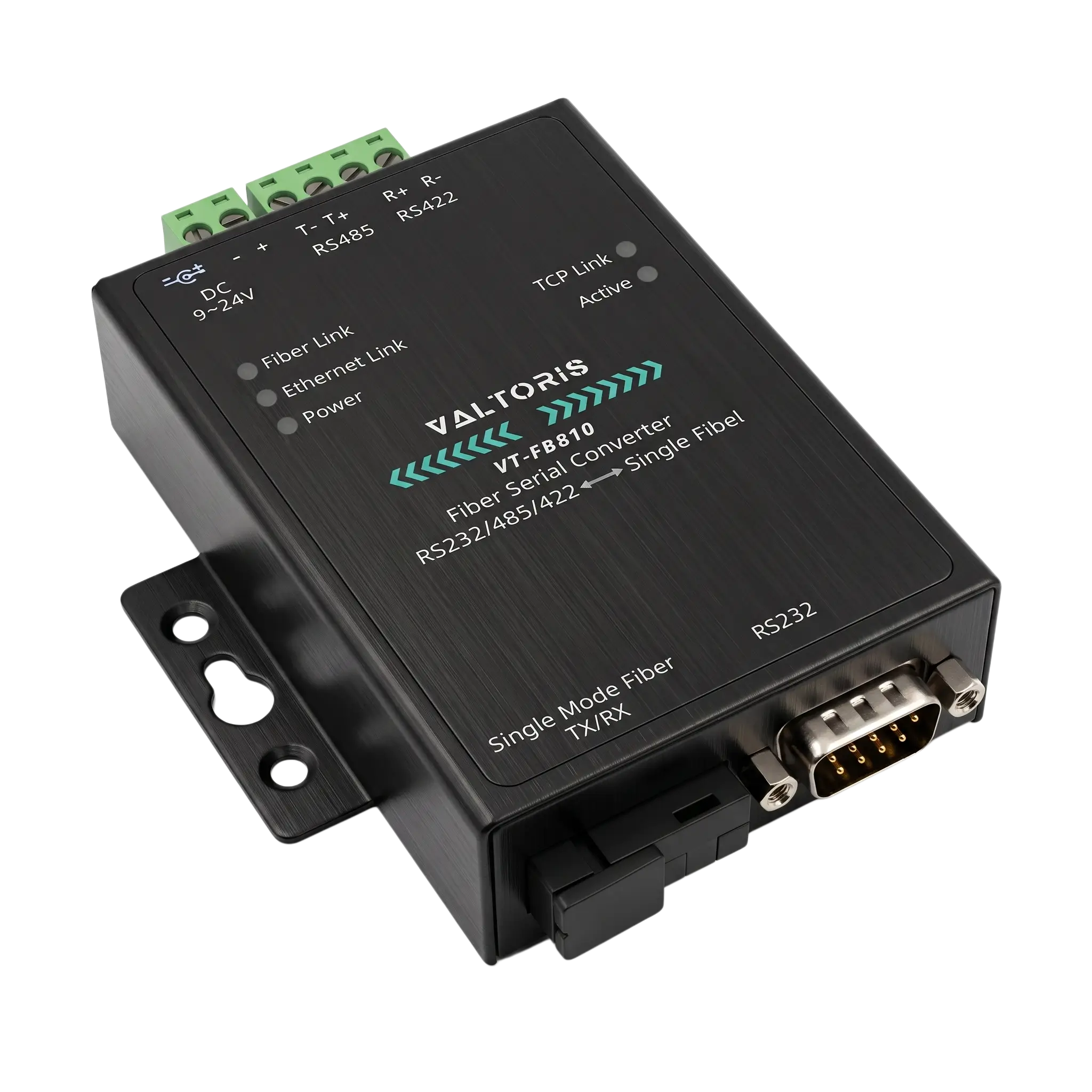 Figure 5: The VT-FB810 front-panel diagnostic LEDs (Fiber Link, TCP Link, Active) allow engineers to instantly isolate Layer 1 physical breaks from Layer 3 protocol failures.
Using the comprehensive LED array of the VT-FB810 (an advanced Ethernet/Serial hybrid converter) as the standard reference, field technicians should follow this rigorous diagnostic sequence:
| LED Indicator | Normal State | Diagnostic Troubleshooting (If Off) |
|---|---|---|
| Power | Solid Green | Check the 9-24V DC input on the terminal block. Ensure polarity (+/-) is not reversed. Make sure the power supply is outputting the correct amperage (357mA@9V minimum for advanced units). |
| Fiber Link | Solid Green | Crucial check: If this is OFF, the optical physical layer is fundamentally broken. Verify the SC connector is fully seated. Verify you have not accidentally paired two A-Ends or two B-Ends. Check the fiber line for severe bends or breaks using an Optical Time Domain Reflectometer (OTDR). |
| Ethernet Link | Solid Green | The RJ45 copper connection to the local switch is down. Test the CAT6 cable with a cable tester. Ensure the local switch port is not administratively shut down or disabled. |
| TCP Link (IP-enabled units) | Solid Green | The physical layers are fine, but the IT networking is failing. The device (acting as TCP Client) cannot reach the destination Server IP. Check gateway settings, subnet masks, and ensure firewall rules are not blocking the designated Port. |
| Active (ACT) | Flashing | This flashes when serial data (RX/TX) is actively passing through the RS232/485 port. If Fiber and TCP Links are solid, but ACT is off, the end-device PLC or sensor is completely silent. Check the RS485 wiring polarity (A to A, B to B). |
By systematically validating the Power, Fiber Link, and Ethernet/Serial Active states, technicians can resolve 95% of installation hurdles on the factory floor without ever opening a command-line interface.
Optical media conversion remains the undisputed champion of industrial network resilience. Whether you are battling the 100-meter copper limitation across a sprawling campus, or fighting catastrophic VFD noise on a dense factory floor, isolating the data transmission onto a glass filament ensures absolute signal integrity for decades to come.
Stop Guessing. Start Transmitting.
Do not let the 100-meter copper limit or crippling EMI noise jeopardize your facility’s uptime. Whether you need to seamlessly extend a 10/100M Ethernet network, bridge legacy RS485 Modbus devices, or power Edge IP PTZ cameras, Valtoris has the exact physical layer hardware you need.
Not sure which A-End / B-End combination matches your conduit layout? Request a Free Architecture Review.
Frequently Asked Questions: Hardware Integration & Fiber Physics
Can I mix different brands of media converters on opposite ends of the fiber?
Yes, but with serious disclaimers. Media converters are transparent at Layer 1. In theory, the two devices will link if they can support the same optical wavelength (e.g., 1310nm), the same fiber mode (Single-mode) and the same data speed (e.g., 100Base-FX). Though if you use Single-Fiber BiDi technology, you have to ensure that Brand X’s A-End wavelength is an exact match to Brand Y’s B-End listening frequency. For industrial control panels, it is highly recommended to use pairs from the same manufacturer to ensure stability and unified troubleshooting.
Why does my converter’s ‘Fiber Link’ LED light up, but I cannot ping the remote device?
The ‘Fiber Link’ LED only confirms that the physical layer of light is successfully traveling between the two optical transceivers. It does not verify data routing. If the link is solid but pings fail, the issue resides higher up in the network layer (Layer 2 or Layer 3). Check for IP subnet mismatches, restrictive VLAN tagging configurations on the connected copper switches, or firewall rules on the end-devices that might be actively dropping ICMP ping packets.
Do I need an optical attenuator if I test two 20km converters over a 3-meter patch cable in the lab?
Yes, this is a critical and often overlooked step. Industrial media converters designed for 20km transmission (like the VT-FB800 series) emit a highly powerful laser. If you connect an A-End directly to a B-End using a short 1-to-3 meter fiber patch cable on your test bench, the intense light can saturate and permanently burn out the optical receiver photodiode. You should always use an inline optical attenuator (typically 5dB to 10dB) when bench-testing long-haul optics over short distances to artificially simulate fiber distance and protect the hardware.
Do I need a crossover or straight-through copper cable to connect the converter to my switch?
Historically, connecting a media converter to a network switch required a straight-through cable, while connecting it directly to a PC’s network interface card required a crossover cable. However, virtually all modern industrial media converters feature Auto-MDI/MDIX technology on their RJ45 ports. This silicon automatically detects the pinout of the connected equipment and internally crosses the transmit/receive lines as necessary, meaning standard straight-through CAT6 patch cables can be used universally.
If the remote fiber gets cut, will the Ethernet port on my local converter drop the link to alert my switch?
Generally, no. Standard unmanaged media converters transparently pass data but do not inherently pass link states. If a backhoe cuts the fiber 5 miles away, the optical ‘Fiber Link’ LED will turn off, but the copper ‘Ethernet Link’ between the local converter and your switch will physically remain UP. This means your switch won’t automatically trigger Spanning Tree (STP) failover. If your network topology relies on rapid automated failover, you must implement a higher-level Managed Industrial Switch or specifically inquire about converters featuring LFP (Link Fault Pass-Through) technology.
