
When 15 Meters Isn’t Enough
If you manage a machine shop with legacy equipment, you are intimately familiar with the “sneaker-net” workflow. Programmers write complex G-code in the engineering office, save it to a USB drive (or floppy disk), walk across the noisy shop floor, and manually load it into the machine controller. As shop floors expand, operators inevitably seek a networked solution. This is where performing a proper CNC RS232 to Ethernet conversion becomes the most critical IT upgrade a machine shop can execute.
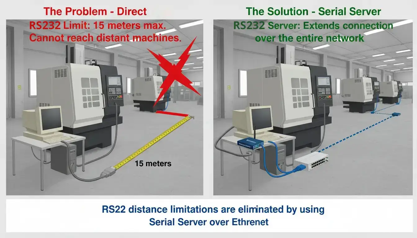
The core problem stems from physics. The EIA-232 standard (commonly known as RS232) was developed for connecting teletypewriters to modems. According to electrical engineering standards, the maximum reliable cable length for RS232 is strictly limited to 15 meters (50 feet) at 9600 baud. As cable length increases, the inherent capacitance of the copper wire begins to round off the sharp, square digital voltage pulses. Eventually, the CNC’s receiver cannot distinguish a binary ‘1’ (-12V) from a ‘0’ (+12V).
You either move the machine to the office, move the PC to the machine, or attempt to run an excessively long, out-of-spec cnc rs232 cable that is highly susceptible to Electromagnetic Interference (EMI) from the factory floor.
Why Upgrade Your CNC from RS232 to Ethernet?
That 15-meter limit dictates your entire shop floor layout. However, distance is only half the battle. In modern manufacturing, the shop floor is an electrically noisy environment. Massive spindle motors, industrial chillers, and Variable Frequency Drives (VFDs) generate immense Electromagnetic Interference (EMI).
RS232 is a "single-ended" signaling protocol. It references its voltage to a single common ground wire. If a VFD induces an electrical spike onto that ground wire, the CNC machine interprets that spike as legitimate data. This leads to corrupted NC files, inexplicable "Parity Errors" on the operator panel, or worse—the machine executing a corrupted line of G-code and driving an expensive tool directly into the fixture.
By implementing a CNC RS232 to Ethernet topology, you bridge the analog world to the digital world. An Industrial Serial-to-Ethernet Converter placed directly at the machine intercepts the short, vulnerable RS232 signals and encapsulates them into robust TCP/IP packets. Ethernet utilizes differential signaling (which inherently cancels out EMI noise) and guarantees data delivery via packet checksums. You effectively bulletproof your communication pipeline from the engineering server all the way to the CNC controller.
RS232 Cable Wiring: Pinouts and Null Modem Cables Explained
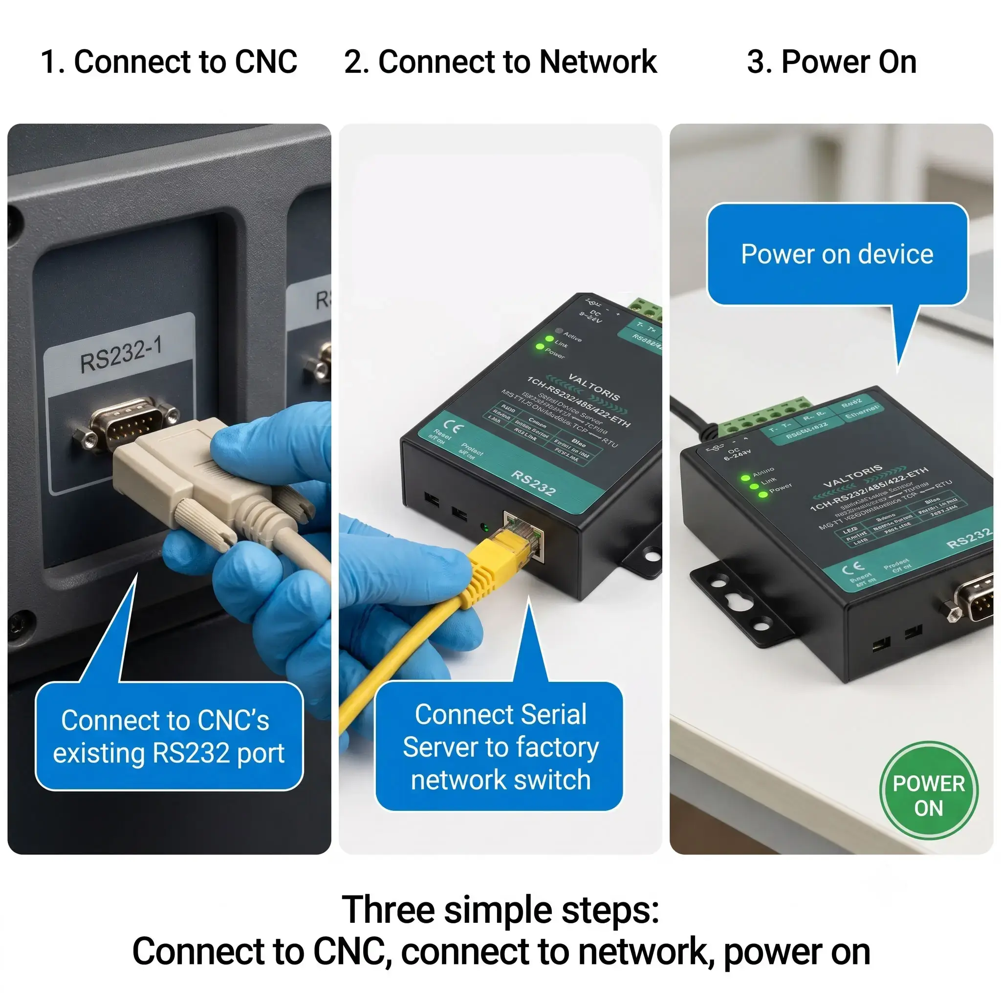
Before touching IP addresses or software, the physical connection must be flawless. Wiring the serial cable incorrectly is the absolute most common reason DNC networking setups fail.
Building Your Own Cables? Read Our Pinout Guide First
If you are crimping your own RJ45 to DB9 connectors to bridge your CNC's serial port to your Ethernet infrastructure, standard TIA/EIA-568-B colors apply, but the serial pin mapping is entirely custom. Read our comprehensive RS232 to Ethernet Cable Pinout guide to see the exact wiring diagrams.
In serial communications, equipment is defined as either DTE (Data Terminal Equipment) or DCE (Data Circuit-terminating Equipment). Historically, a computer (DTE) connected to a modem (DCE) using a "straight-through" cable.
However, CNC machines are almost universally wired as DTE devices. Furthermore, Industrial Ethernet Gateways are also configured as DTE devices. When you connect two DTE devices together, their Transmit (TX) pins crash into each other, and their Receive (RX) pins listen to dead air.
You must use a Null Modem (crossover) cable. Proper Null Modem Wiring physically crosses the TX pin on the gateway to the RX pin on the CNC, and vice versa. Without this, no amount of software troubleshooting will work.
Older CNC controllers (Fanuc 0i/18i, Haas, Mazak, etc.) also use hardware flow control to prevent incoming data when buffers are full. You must often bypass or satisfy these legacy hardware requirements by bridging specific pins (like RTS to CTS) directly on the DB25 connector at the machine side.
Decoding the Software Configuration Process
Simply plugging an Ethernet cable into an adapter does not magically make your CNC appear on the network. Legacy DNC software (like Cimco Edit, Predator DNC, or DNC4U) was written decades ago. It expects to see a physical COM1 or COM2 port on your motherboard. It does not know how to send data to an IP address like 192.168.1.50.
To bridge this gap, you must utilize Virtual COM Port (VCP) technology. Here is the operational logic behind configuring the system:
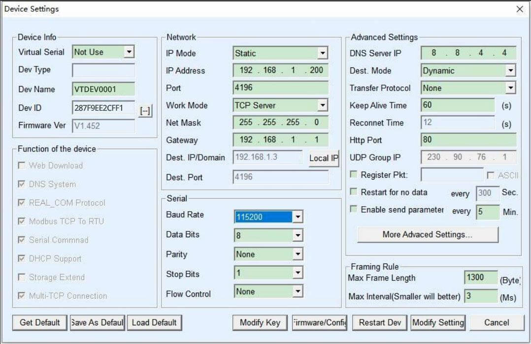
- The Network Layer (TCP/IP Setup): First, assign a static IP address to your Ethernet Gateway. You must configure the gateway to operate as a TCP Server, listening on a specific port (e.g., Port 4196).
- The Application Layer (VCP Binding): Install the VCP management software on your engineering PC. You instruct this software to create a fake, virtual COM port (e.g., COM5) and "bind" it to the IP address and port of your gateway over the LAN.
- Strict Parameter Alignment: This is where 90% of software setups fail. The baud rate, data bits, parity, and stop bits must match perfectly across three distinct locations: The CNC Machine Parameters (e.g., Fanuc Parameter 20), the Ethernet Gateway's web interface, and your DNC Software. If your machine expects
4800-7-E-2then all three nodes must show that exact string.
Operational Workflow on the Shop Floor
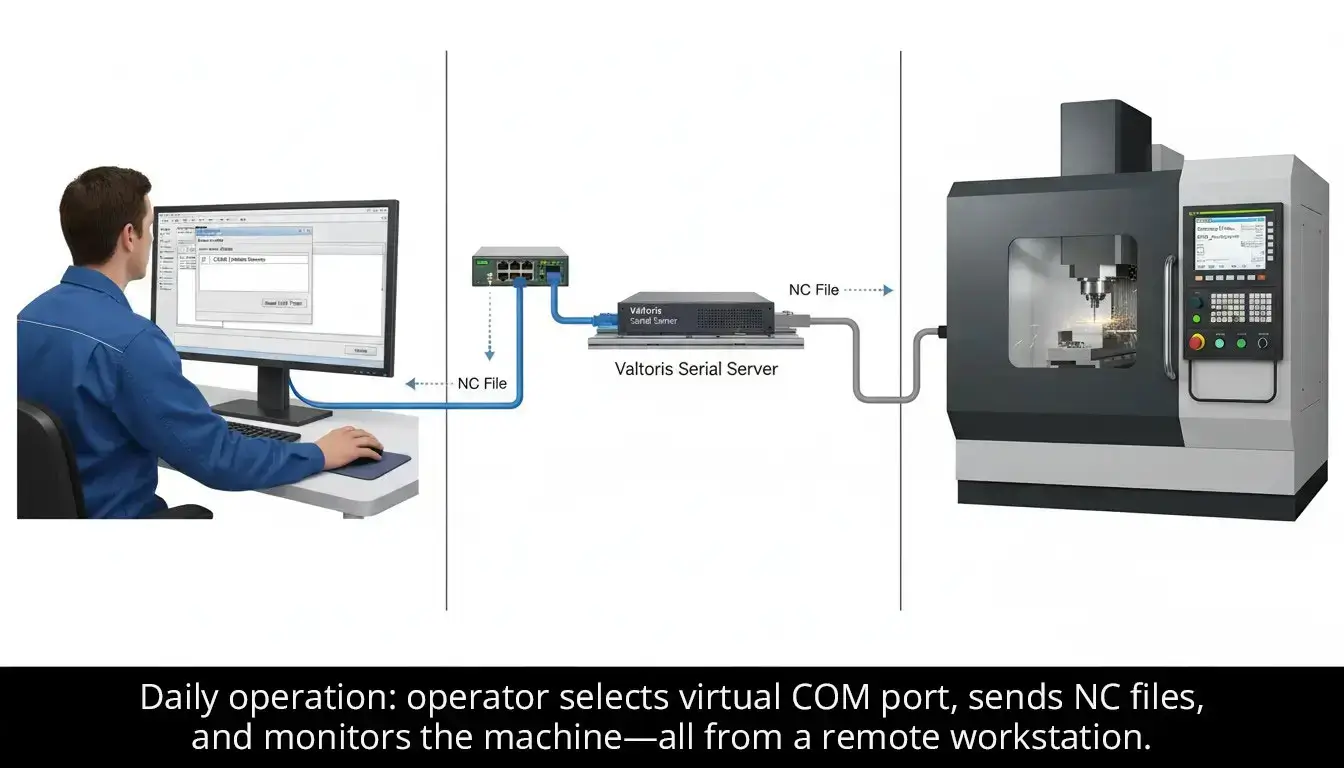
With the physical wiring in place and the virtual ports bound, the daily operation becomes completely seamless for the machinist. No more dependence on USB drives.
- The programmer exports the G-code from their CAM software (like Mastercam or Fusion 360) directly into the shared DNC folder on the engineering server.
- The shop floor terminal of the machinist opens the CNC communication software and selects the assigned virtual COM port (e.g. COM5) for this specific machine.
- They hit "Send" and the file is sent across the LAN to the machine, ignoring any constraints of physical distance.
- Monitor machine status and data in real time from any location with network connectivity.
Technical Advantages for CNC Applications
Migrating from consumer-grade USB-to-Serial cables to an industrial Ethernet architecture provides structural advantages that directly impact shop floor productivity.
Guaranteed Data Integrity
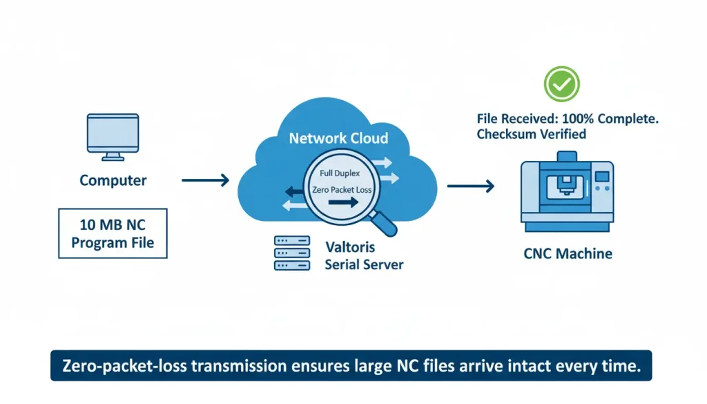
- Full-duplex, zero-packet-loss transmission: Ensures large NC files download completely without corruption.
- Native flow control support: supports XON/XOFF protocols, accurately handles for strict compatibility with CNC communication standards.
- High-speed mode: Optimized for massive CNC data applications for efficient file transfer.
Extended Operational Capabilities
- Unrestricted access: The remote monitoring and control feature enables live access from any connected workstation.
- Overcome distance limits: The network architecture completely removes the 15-meter RS232 limitation, so you can put machines anywhere on the shop floor.
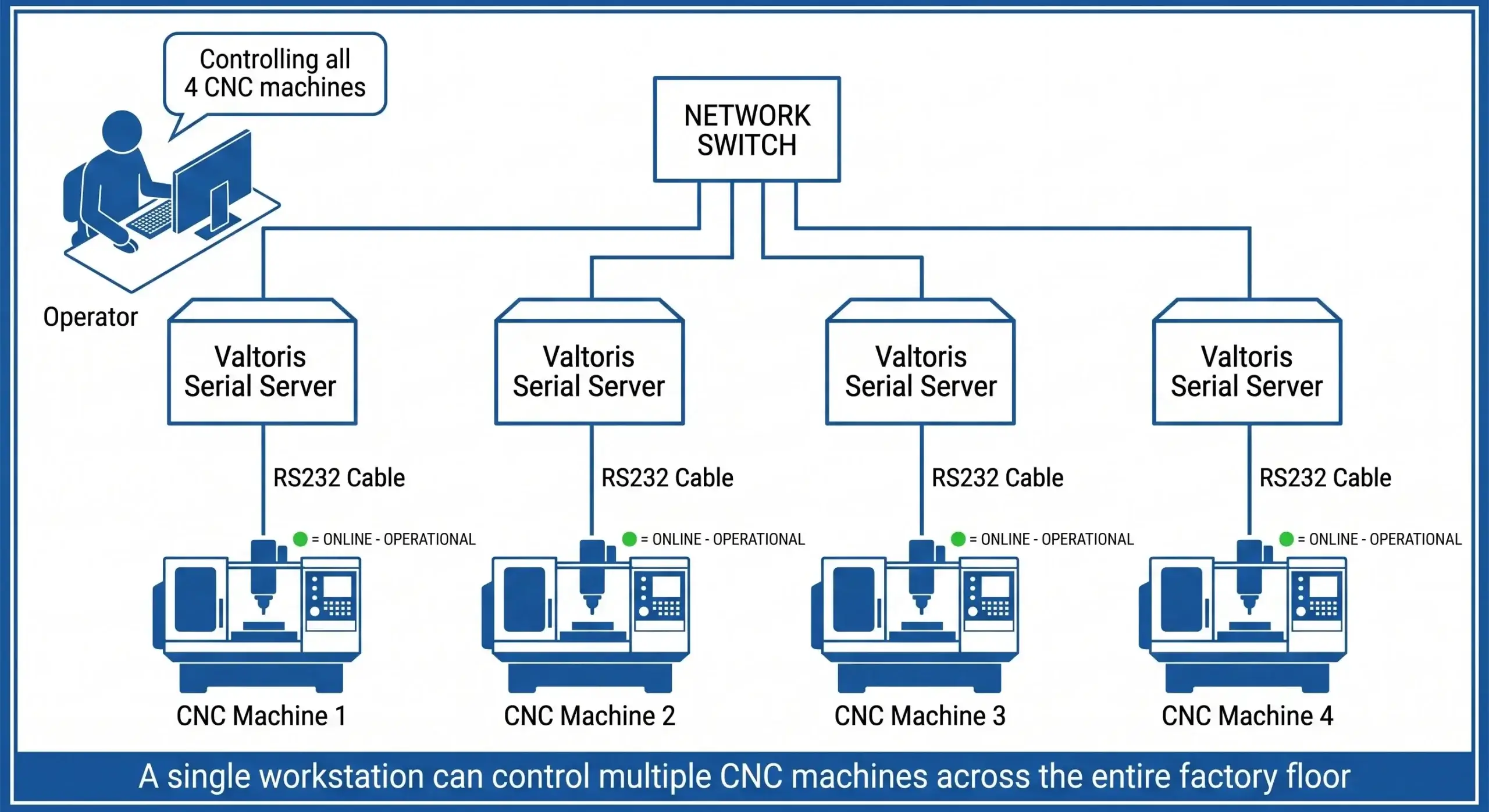
- Centralized command: Multi-port serial server capability for single computer control of multiple CNC machines.
Industrial-Grade Reliability
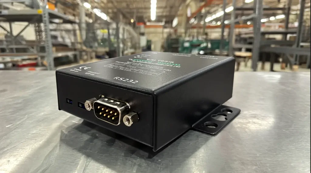
– Industrial serial server design for stable operation in manufacturing environment .
– Automatic re-connection features keep communication going during network interruptions.
– LED status indicators provide instant visual indication of connection and data transmission status.
How to Drip Feed Large G-Code Files Over Ethernet (And Avoid Alarm 086)
For a basic rs232 cnc file transfer (sending a 20KB facing program to the machine's memory), almost any adapter will work. However, if you are machining complex 3D mold cavities, your G-code file might be 50 Megabytes. Older CNC machines typically have less than 256KB of internal memory. Therefore, you must "Drip Feed" (DNC) the program line-by-line while the machine cuts metal.
Drip-feeding is a highly precarious balancing act. The engineering computer is sending data at a rapid pace over the network. The CNC machine can only process blocks of G-code at the physical speed the cutting tool is moving. When the CNC's small internal memory buffer hits 80% capacity, it desperately transmits an XOFF (Stop Transmitting) signal back down the serial line.
This is precisely where cheap, commercial-grade USB-to-Serial adapters or generic Ethernet bridges fail catastrophically. They lack the localized, high-speed hardware required to intercept and act upon that XOFF signal instantaneously. Unaware of the CNC's distress signal, the cheap adapter continues to blindly push data packets. The CNC's memory overflows, the machine abruptly stops interpolating, leaving a gouge in the workpiece, and the screen flashes a devastating Buffer Overflow (such as Alarm 086 on a Fanuc controller).
To solve this, industrial environments rely on dedicated Industrial Serial Servers. These professional-grade gateways act as a localized network shock absorber. If the CNC is set up for Software Handshaking (XON/XOFF), the gateway uses its own internal Hardware FIFO (First-In, First-Out) memory buffers. The high-speed Ethernet payload is absorbed locally, the transmission is stopped immediately when the XOFF command is received from the machine and resumed gracefully when the CNC sends the XON (Resume) signal. It feeds the G-code to your CNC at exactly the baud rate it demands. Your machining is continuous and stutter-free, even for 3D surfacing over multiple days.
Scale Your CNC Network Architecture
Whether you are networking a single legacy Fanuc mill or an entire high-density automated cell, select the exact RS232-to-Ethernet port configuration required to eliminate buffer overflows.
| Model Series | CNC Serial Ports | Ethernet Architecture | Action |
|---|---|---|---|
| 1CH-RS232/485/422-ETH (V) | 1 × Port (3-in-1) | Single Node (1 × RJ45) | View Specs → |
| 4CH-RS232/485/422-ETH | 4 × Ports (High Density) | Cascade (2 × RJ45) | View Specs → |
| 8CH-RS232/485-ETH | 8 × Ports (Cell Control) | Cascade (2 × RJ45) | View Specs → |
Expert Troubleshooting & FAQs
You go from a localized RS232 cable to a decentralized Ethernet architecture . You connect two completely different ages of technology. Ethernet relies on packet switching and non-deterministic timing, whereas legacy CNC controllers expect an unbroken, highly synchronized stream of electrical pulses. Use this FAQ, curated from core machinist communities, to isolate your faults.
What IP address do I assign to the CNC machine itself?
Should I configure the Ethernet Gateway as a TCP Server or TCP Client?
How can I test if the problem is my cable or the network configuration?
Will this setup allow me to extract machine monitoring data (MTConnect / MDC)?
Architecting Your Factory Network Upgrade
Bringing legacy CNC machines up to an Ethernet backbone requires matching the right controller with the right gateway. Avoid buffer overflows and mismatched pinouts—tell us what controllers you are running below. Our automation engineers will map out your topology and suggest the exact hardware configuration needed for zero-packet-loss DNC transfers.
