
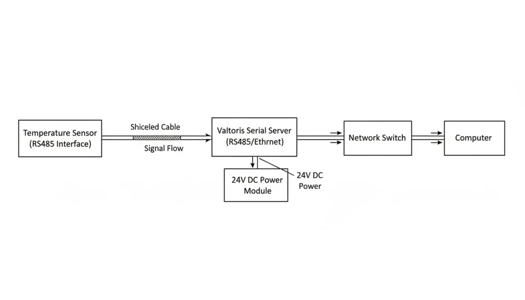
Putting temperature sensors all over a large factory floor poses a basic networking problem: connecting the scattered RS485/RS232 nodes to a central SCADA control room. Running separate cables for each furnace or refrigerator can cause signal problems, and messy wiring can limit your options. Using expensive repeaters, on the other hand, will raise the cost of your project.
This gap is elegantly bridged by a serial-to-Ethernet converter. It receives the RS485 output from your edge sensors, wraps it in TCP/IP packets and sends it over your existing Ethernet network. This architecture allows you to view live temperature telemetry from any authorized workstation, whether on the local factory floor or in a remote centralized control room.
This guide walks through setting up a Valtoris single-port serial server with temperature sensors. We’ll cover the hardware connections, software configration, and a few real-world tips we’ve picked up from actual installations.
⚡ Quick Specs: RS485 vs. Ethernet for Sensors
| Specification | RS485 (Field Level) | Ethernet (Control Room) |
| Max Distance | 1,200 meters (theoretical) | 100 meters (Copper) / 10km+ (Fiber) |
| Topology | Daisy-chain (Linear) | Star / Ring |
| Protocol Support | Modbus RTU / ASCII | Modbus TCP / MQTT |
| Role in Network | Sensor Data Collection | High-Speed SCADA Backhaul |
Temperature Sensors and Serial Communication: A Quick Background
Before we start setting things up it is useful to know what kind of sensors we are working with. Temperature sensors are really common—they make up roughly 50% of all industrial sensors according to a 2021 IEEE industry report. The main kinds of temperature sensors include:
- Thermocouples – rugged, wide range, but low accuracy
- Thermistors – high accuracy over a narrow range
- Analog sensors (4–20mA, 0–10V) – need analog input modules
- Digital sensors (DS18B20, SHT series) – often use 1-Wire or I²C, but some have serial output
Most industrial temperature sensors communicate data over RS485 with the Modbus RTU protocol. The main advantage of RS485 is that it is multi-drop, so you can daisy-chain several sensors along a single two-wire twisted pair. This linear topology greatly reduces cable clutter and installation costs to deploy dense sensor arrays throughout a facility.
The Valtoris serial server that we are using can handle RS232, RS485 and RS422. So it can work with temperature sensors that you will come across.
What You’ll Need
- A Valtoris single-port serial server (model depends on your sensor’s interface: RS232, RS485, or RS422)
- Your temperature sensor(s) with serial output
- Ethernet cable and network switch
- Power supply (9–24V DC, terminal block or DB9 depending on model)
- A computer with Vircom software (free from Valtoris) installed
Step 1: Hardware Connections
- Connect the sensor to the serial server
- If your sensor uses RS232, use a straight-through DB9 cable (or wire the appropriate pins: RX, TX, GND).
- For RS485, connect A(+) and B(-) terminals. If you have multiple sensors, daisy-chain them (A to A, B to B).
- For RS422, connect TX+, TX-, RX+, RX- as needed.
- Connect the server to your network
Plug an Ethernet cable from the server’s RJ45 port into a standard network switch that’s connected to your computer. - Power up
Apply 9–24V DC power via the screw terminals (or DB9 for RS232 models). The LED indicators should light up.
Step 2: Software Configuration
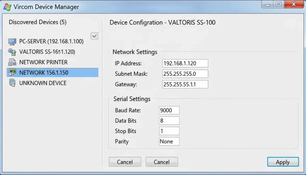
The Valtoris serial server comes with a free utility called Vircom. Download and install it on your computer.
- Open Vircom – It will automatically discover any Valtoris serial servers on the same network. Select yours from the list.
- Set the IP address – By default, the server uses DHCP. If you prefer a static IP (recommended for SCADA integration), go to the network settings and assign one, e.g., 192.168.1.188. Make sure it’s on the same subnet as your computer.
- Configure serial parameters – Match these to your sensor’s requirements: baud rate (e.g., 9600), data bits (8), stop bits (1), parity (none). This information is in your sensor’s datasheet.
- Create a virtual COM port – In Vircom, go to the “Virtual Serial Port” tab and add a new port (say COM5). Bind it to your serial server. Now any software on your PC can access the sensor through COM5 as if it were directly connected.
Step 3: Reading Sensor Data
Now that the hardware and software are set up, you can start collecting data.
- If your sensor uses a custom protocol – Open your own application (e.g., Python script, LabVIEW) and open the virtual COM port (COM5). Read and parse the data according to the sensor’s protocol.
- If your sensor uses Modbus RTU – You can use SCADA software like KingView, WinCC, or even free tools like Modbus Poll. Configure the software to communicate via COM5, with the correct Modbus slave ID and register addresses.
- If your sensor supports Modbus TCP – Some newer sensors have built-in Ethernet. In that case, you can bypass the virtual COM port and have the SCADA talk directly to the serial server’s IP address (e.g., 192.168.1.188) using Modbus TCP.
| Sensor Type | Interface | Protocol | Typical Baud Rate | Configuration Notes |
|---|---|---|---|---|
| PT100 RTD (with transmitter) | RS485 | Modbus RTU | 9600 | Slave ID=1, read holding registers |
| K-type thermocouple module | RS232 | Custom ASCII | 4800 | Send command “READ” to get temperature value |
| SHT75 digital sensor | RS232 | Custom binary | 19200 | Data format: 2 bytes temp + 2 bytes humidity |
| Infrared thermometer | RS485 | Modbus RTU | 115200 | Read input register address 0x0001 |
What We’ve Learned from Real Installations
Over the years, we’ve helped set up dozens of temperature monitoring systems using serial servers. Here are a few things that aren’t always obvious from the manuals:
- Cable length matters: While the RS485 standard theoretically reaches 1200 meters, high-EMI factory environments often limit reliable transmission to under 800 meters. Pushing beyond this threshold without proper industrial shielding or fiber optic converters invites data corruption.
📐 Engineering Note: The Shielding Factor While RS485 is robust, running sensor cables parallel to high-voltage factory equipment (like VFDs or large motors) will introduce severe EMI (Electromagnetic Interference). Always use shielded twisted pair (STP) cables and ground the shield at one end only to prevent ground loops.
💡 Pro Tip: Pre-Configuration Before deploying your serial server on the factory floor, configure its IP address and Modbus gateway settings on a local desk switch first. Troubleshooting network pings on a laptop while balancing on a ladder in a noisy plant is a nightmare you want to avoid.
- Ground Loops Cause Headaches: When sensors are distributed across large physical distances, variations in ground potential can easily corrupt your serial data. To prevent this, always utilize optically isolated RS485 converters—a standard feature in the Valtoris lineup—and ensure your cable shielding is grounded at only one end of the bus to prevent current loops.
- Modbus addressing – When you connect sensors together each sensor must have its own special Modbus address. Some of these sensors have the address 1 when they come from the factory. So you will have to change the Modbus address of each sensor one at a time using software. You have to make sure each sensor has a Modbus address.
- Power separately – Many sensors draw power from the same cable as data (RS485 uses two wires for both). If you have many sensors, voltage drop can be an issue. Consider using a separate power supply or a powered hub.
DIY Cable vs. Serial Server: Which One Makes Sense?
You might be thinking: why not just run a long serial cable or use a USB-to-serial adapter? Here’s a quick comparison:
| Solution | Pros | Cons |
|---|---|---|
| Long serial cable | Low cost, simple | Distance limited (RS232 15m, RS485 up to 1200m but needs termination), prone to interference |
| USB-to-serial adapter | Plug-and-play, cheap | One adapter per sensor, distance still limited, messy with many devices |
| Serial server | Unlimited distance (via network), multi-device sharing, remote access, noise immune | Higher initial cost, basic networking knowledge needed |
If you have a sensor that is close to the computer a USB adapter is okay.. When you have multiple sensors all over a factory floor a serial server is a good idea. The serial server helps with reduced cabling. It is easier to maintain the sensors. This is because the serial server can handle sensors at the same time. So, for sensors a serial server is a better choice.
Final Thoughts
Setting up temperature monitoring is really not that hard. You can use a server to get the data from your existing sensors on the network. This way you do not have to get sensors or run really long cables.
The Valtoris serial server we used here is very good. It works well for things like monitoring the temperature in a greenhouse or keeping track of the temperature in a freezer.. What is more important, than what brand you use is knowing your own setup. This means you need to know what sensors you have how apart they are and what software you will use to make it all work.
If you are putting in a system or updating an old one we hope this guide helps you figure out what to do.. If you run into a problem you can usually find help on a forum or talk to a support engineer who has seen the problem before.
📊 Hardware Selection Matrix: Which Serial Server Do You Need?
| Application Scenario | Sensor Count | Topology Limitation | Recommended Hardware | Action |
|---|---|---|---|---|
| Single Furnace / Machine | 1 – 15 nodes | Linear daisy-chain | 1-Port Serial Server Compact DIN-rail, wide voltage | View VT-1CH Specs → |
| Distributed Floor (Scattered) | 15 – 50 nodes | Forced Star Topology | 4-Port RS485 Hub + Server Optically isolated branch splitter | View Hub Solution → |
| High-Speed Real-time SCADA | 50+ nodes | Parallel multi-bus | 8-Port Serial Gateway Multi-channel parallel polling | View 8-Port Gateway → |
Quick Reference: Pinout for Common Connections
“💡 Field Engineer Cheat Sheet: Bookmark this URL on your mobile device or save the Pinout Table below for instant reference when wiring DB9 connectors inside dark control cabinets.”
| Interface | Signal | DB9 Pin | Suggested Wire Color |
|---|---|---|---|
| RS232 | TX | 2 | Yellow |
| RS232 | RX | 3 | Green |
| RS232 | GND | 5 | Black |
| RS485 | A(+) | – | White |
| RS485 | B(-) | – | Blue |
| RS485 | GND | – | Black (optional) |
| RS422 | TX+ | – | White |
| RS422 | TX- | – | Green |
| RS422 | RX+ | – | Red |
| RS422 | RX- | – | Black |
Frequently Asked Questions
Q1: Can the serial server power the temperature sensors directly over the RS485 port?
Q2: Will there be data latency if I daisy-chain 20 temperature sensors on a single RS485 port?
Q3: The field conduit layout makes daisy-chaining impossible. Can I wire the sensors in a Star Topology?
Q4: Our SCADA software only supports Modbus TCP, but the temperature sensors output Modbus RTU. Can this server translate the protocols?
Need an Engineer to Verify Your Sensor Wiring Topology?
Not sure if you need optically isolated RS485 hubs, terminating resistors or just plain serial servers on your factory floor? Preventing ground loops or data corruption. Please enter your node count and physical distances below. Our application engineers will review your layout and send you a verified hardware architecture recommendation within 24 hours.