

If you work with industrial controls, you have encountered Modbus RTU. It’s been around since 1979, and it’s still the most widely used serial communication protocol in factories, water treatment plants, oil and gas facilities, and building automation systems. Why? Because Modbus RTU is simple, reliable and works over massive distances. According to the 2025-2026 Industrial Networking Market Shares, while industrial Ethernet now holds over 63% of the market, the installed base of Modbus RTU remains a multibillion-dollar segment, primarily driven by legacy upgrades and the expansion of distributed control systems (DCS).
While market reports predict the remote I/O sector will hit $3.12 billion by 2030, field engineers know the real story on the ground. This growth isn’t just about adding shiny new sensors; it’s about forcing legacy equipment to communicate flawlessly within modern Industry 4.0 and SCADA architectures.
Modbus RTU vs. Modbus TCP: Choosing the Right Communication Protocol
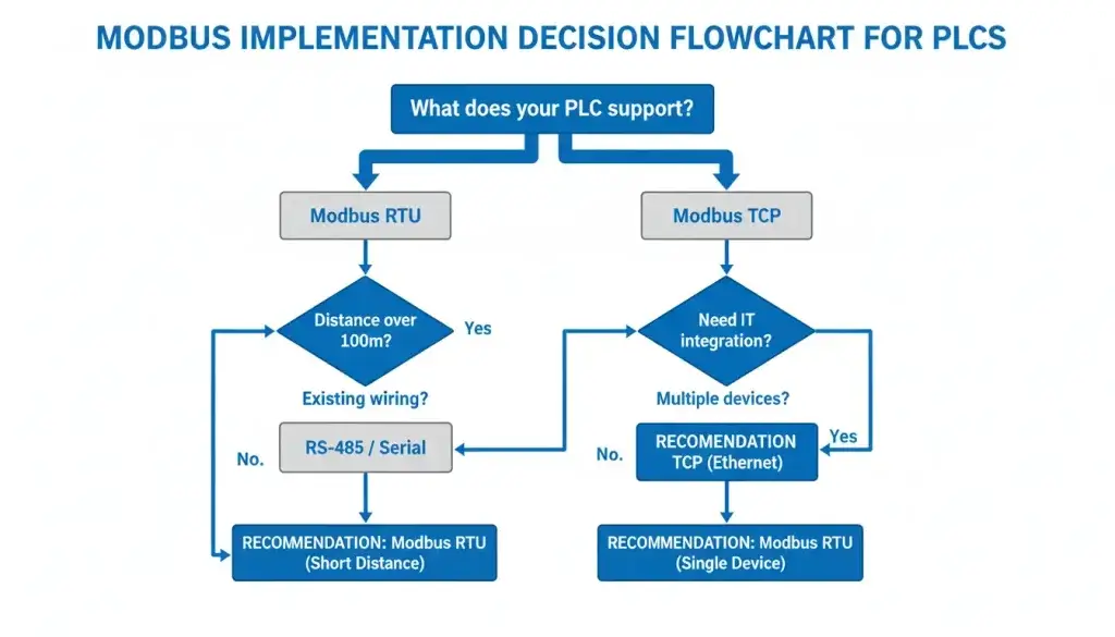
The first hurdle in any I/O project is deciding between Modbus RTU (Serial) and Modbus TCP (Ethernet). In 2026, this choice is no longer just about “wires vs. cables”—it’s about the speed of data integration into cloud-based platforms.
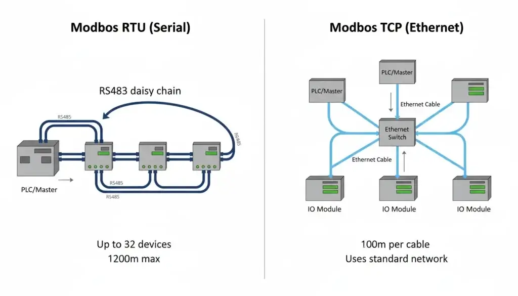
Modbus RTU remains the definitive choice for remote monitoring due to its extreme cost-effectiveness. Utilizing the robust RS485 physical layer, it enables reliable data transmission across 1,200-meter cable runs. It is engineered for daisy-chaining multiple devices over a single twisted pair, significantly reducing installation labor. Conversely, Modbus TCP encapsulates Modbus registers into standard IP packets, delivering massive bandwidth and integrating seamlessly directly into corporate IT infrastructure.
| Feature | Modbus RTU | Modbus TCP |
| Physical connection | RS485 (two wires) | Ethernet (RJ45) |
| Distance | Up to 1200m | 100m (copper) / longer with fiber |
| Devices per network | 32 (typically) | Hundreds (with switches) |
| Setup | Address switches, termination resistors | IP addresses, network switches |
| Best for | Factory floors, long distances, simple networks | Office networks, integration with IT systems, large systems |
Matching I/O Types to Your Sensors: Digital, Analog, and Specialized Inputs
A fatal error in automation projects is failing to accurately match the module’s electrical I/O capacity to field devices like limit switches, pressure transmitters, or motor starters. 2026 market data shows that Digital Signal modules still hold the highest market share (valued at over $927 million), but the demand for mixed-signal nodes is accelerating rapidly.
Digital Inputs (DI)
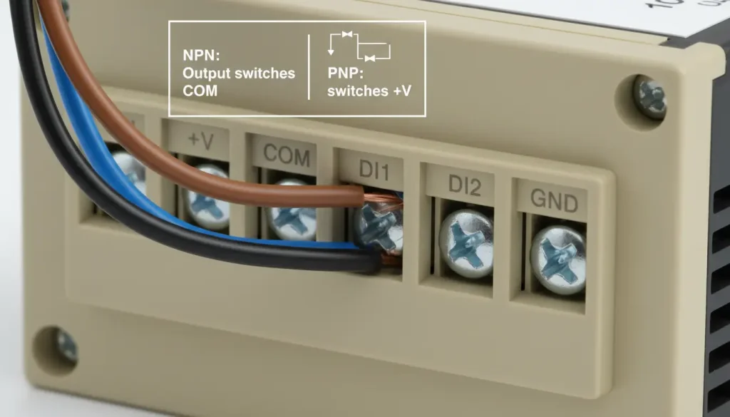
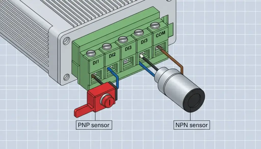
Digital inputs detect binary (on/off) signals. Limit switches, push buttons, proximity sensors, and dry relay contacts fall into this category. Key specifications include the input architecture: Sinking (NPN) or Sourcing (PNP). Most modern industrial modules feature universal inputs capable of detecting both.
Actionable Guide: Audit the on/off sensors at your panel location and mandate a 10-20% expansion buffer. That is your absolute minimum DI count. If you utilize 6 sensors today, specifying an 8-channel module prevents future recabling disasters.
Digital Outputs (DO)
Digital outputs drive field actuators—relays, warning beacons, solenoid valves, and motor starters. Specifying the wrong DO type will result in welded contacts or burned logic boards. You must choose between two architectures:
| Output Type | Characteristics | Best For |
| Relay (Mechanical) | Mechanical contacts, handles AC/DC, up to 5-10A | High power loads, mixed voltage panels |
| Transistor (Solid State) | Solid state, microsecond switching, DC only | Low power, high-frequency continuous cycling |
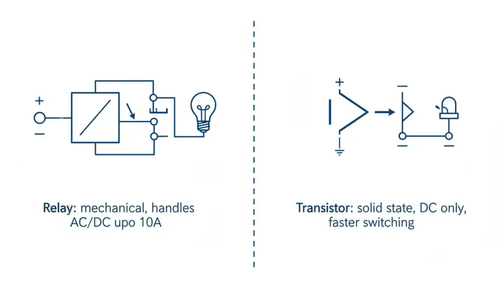
While relay outputs are ideal for driving high inductive loads and mixing AC/DC power, they possess a finite mechanical lifespan. Transistor outputs switch in microseconds and never wear out mechanically, but are strictly limited to low-power DC circuits.
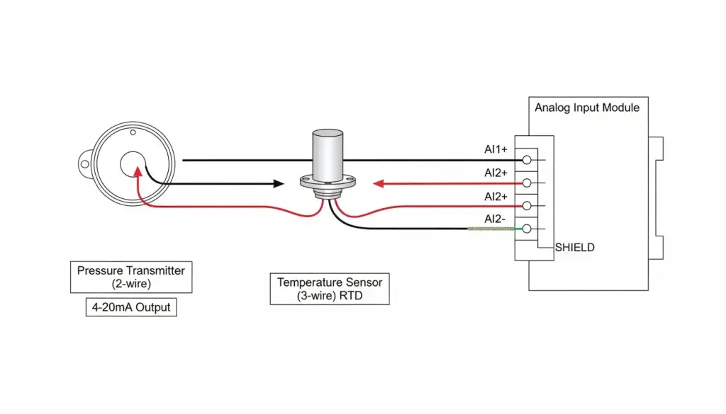
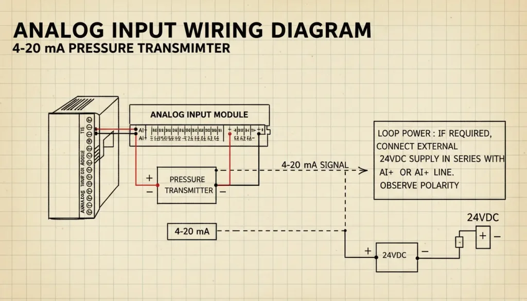
Analog Inputs (AI)
Analog inputs acquire continuous variable data from field sensors like pressure transmitters, RTD temperature probes, and ultrasonic flow meters.
Resolution: Ensure the module’s ADC (Analog-to-Digital Converter) meets your precision requirements. Standard modules feature 12-bit (4096 steps), while critical analytical applications demand 16-bit (65536 steps) resolution.
Ensuring Industrial Reliability: Isolation, Noise Immunity, and Operating Temperatures
Consumer-grade electronics perish rapidly in harsh industrial environments. Factory floors present severe electromagnetic interference (EMI/RFI), dangerous ground loop potentials, and extreme thermal shock. The physical protection of the I/O module is paramount.
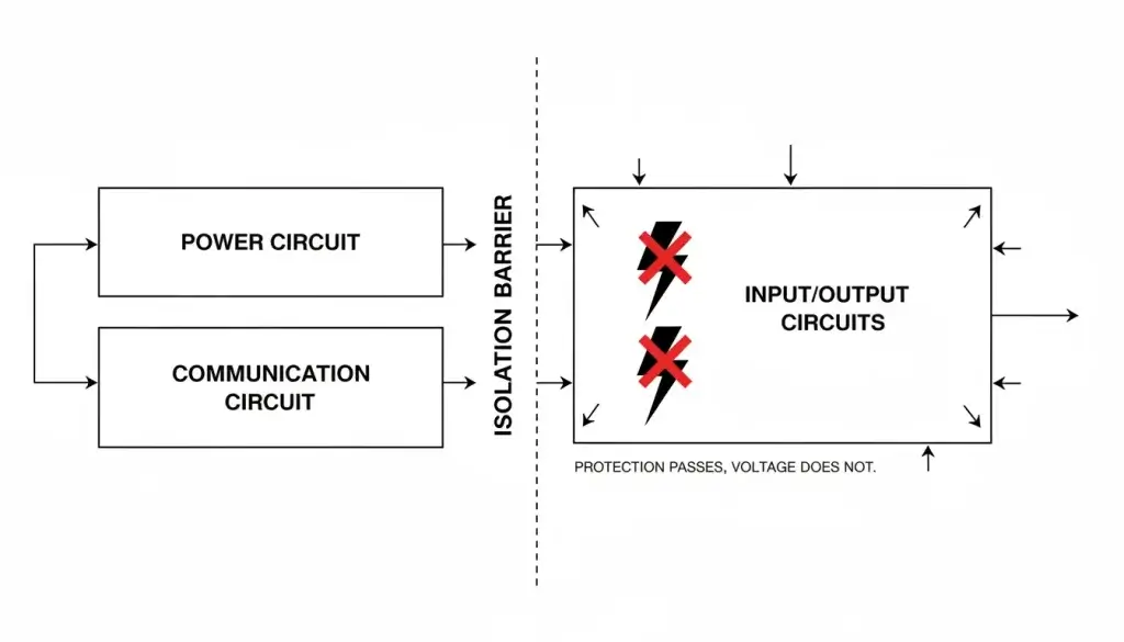
Galvanic Isolation
Galvanic isolation physically decouples the field-side wiring from the internal communication logic using optocouplers. This is mandatory when bridging devices across multiple buildings (to prevent ground potential destruction) or when massive cable runs act as antennas for EMI noise. Typical industrial isolation is rated at a minimum of 1500V or 3000V.
Consider this real-world failure analysis: A municipal water utility deployed non-isolated I/O modules across a sprawling campus. During a minor electrical storm, an induced voltage surge travelled up the RS485 line, destroying three modules and the main $8,000 SCADA PLC. They subsequently upgraded the entire facility to 3000V isolated modules—which cost nominally more upfront, but completely eliminated the risk of catastrophic cascading hardware failure.
| Parameter | True Industrial Grade | Commercial/Consumer Grade |
| Operating Temperature | -40°C to +85°C | 0°C to 50°C |
| Isolation Voltage | 1500V to 3000V | None or minimal |
| Power Supply | 9-24V DC (wide input terminal) | 5V or 12V fixed (barrel jack) |
| EMC Protection | ±15kV ESD, severe surge protection | Basic or none |
Industrial temperature ratings ensure the module survives punishing summer heat in unventilated outdoor NEMA enclosures or freezing conditions in remote pump stations. Standard 35mm DIN rail mounting ensures modules remain secured in high-vibration manufacturing environments.
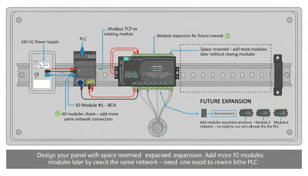
Scalability and Expansion: Planning for Future I/O Capacity
Automation architectures are inherently dynamic. Integrators frequently worry that adding a handful of field sensors post-commissioning will force the purchase of an entirely new master control rack.
Take the case of a food packaging plant that deployed 8-channel modules on a new conveyor line without planning for expansion. When they required two additional proximity switches a year later, they were forced to procure a second I/O module and extensively rewire the control panel. The combined hardware and labor cost exceeded $1,200—an expense entirely avoidable had they simply specified a 16-channel module during initial design.
To eliminate prohibitive expansion costs, specify modules that natively support RS485 daisy-chaining or feature pluggable backplane designs. Furthermore, advanced dual-interface modules can handle Modbus TCP over Ethernet and Modbus RTU over RS485 simultaneously, acting as an active bridge and allowing for seamless future network scaling.
Simplifying Configuration and Modbus Addressing Setup
Configuring baud rates, station IDs, and aligning hexadecimal Modbus register addresses is historically the most labor-intensive phase of field commissioning. Intuitive configuration tools are absolutely essential.
Source your hardware from manufacturers that provide transparent configuration utilities and explicit register mapping tables. If your module establishes a physical link but the PLC receives garbled hexadecimal data, it is almost exclusively a baud rate mismatch or incorrect parity/data bits. Note that the relationship between baud rate and physical transmission distance is strictly inversely proportional:
| Baud Rate | Maximum Distance (approx.) |
| 9600 bps | 1200 m (Optimal for long runs) |
| 19200 bps | 1000 m |
| 38400 bps | 800 m |
| 115200 bps | 400 m (Requires extremely clean wiring) |
| Source: RS485 physical layer standards according to TIA/EIA-485 |
⚙️ Interactive I/O Module Specifier
Stop digging through datasheets. Click your panel requirements below to instantly determine the correct Valtoris I/O hardware for your topology.
Real-World Application Decision Framework
How to match the exact module to your field topology? Let’s review three practical engineering examples:
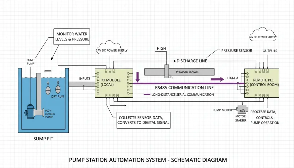
Example 1: Small Pump Station (Remote Telemetry)
- Sensor Requirements: 4 float switches (DI), 2 pressure transmitters (4-20mA AI), 1 pump control relay (DO), 1 alarm beacon (DO).
- Environment: Located outdoors in an unheated NEMA enclosure.
- Recommended Architecture: A highly cost-effective 4-channel Modbus RTU I/O module featuring a strict –40°C to +85°C thermal rating and 1500V optical isolation.
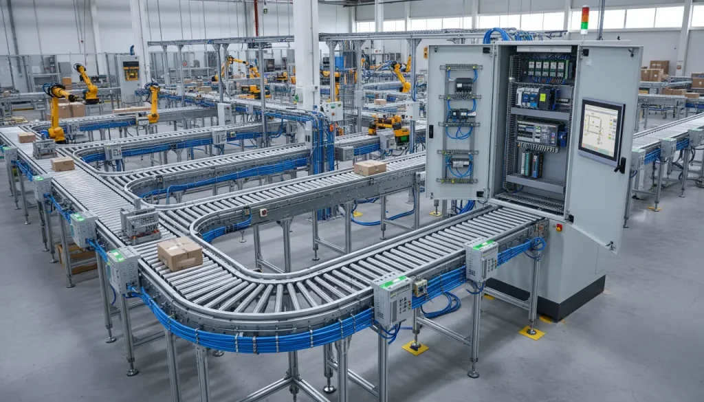
Example 2: Dense Factory Conveyor Monitoring
- Sensor Requirements: 12 proximity sensors (DI), 8 photoelectric eyes (DI), 6 motor contactors (DO), 2 variable frequency drives (4-20mA control, AI).
- Environment: Located on the active factory floor, ambient temperature 0-50°C, heavy VFD electrical noise.
- Recommended Architecture: Two 8-channel Ethernet I/O modules (8 DI, 8 DO, 8 AI each). The built-in Ethernet switch allows seamless daisy-chaining directly into the IT backbone while providing massive future expansion capacity.
Example 3: Dynamic System Expansion
Current Topology: 8 field sensors, 4 output actuators.
Anticipated Phase 2: Addition of 4 more analytical sensors next fiscal year.
Strategic Specification: When designing a dynamic control panel, prioritize modules featuring modular backplanes or built-in protocol bridging. A multi-interface node allows you to absorb immediate serial RTU devices today, while maintaining open Ethernet ports for high-bandwidth TCP expansion modules tomorrow—eliminating the need to rip out and replace your core master PLC.
Wiring and Installation Best Practices
Even the highest-grade isolated module will drop packets if the physical wiring layer is compromised. To guarantee zero polling timeouts, adhere strictly to these industrial RS485 standards:
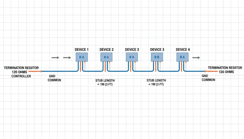
1. Cable Specification: Mandate 120-ohm shielded twisted-pair (STP) cable (e.g., Belden 3105A). Never use standard CAT5/6 for long RS485 serial runs.
2. Shield Grounding: Terminate the drain wire to Earth Ground at one end only (preferably the Master PLC side) to prevent the shield from acting as a massive ground loop antenna.
3. Impedance Termination: Install a 120Ω termination resistor in parallel across the Data A and Data B terminals at the absolute first and last devices on the trunk line.
4. Topology Enforcement: Keep stub lines (the drop from the main trunk to the device) as short as physically possible. Never wire a “Star” topology without using an Active RS485 Hub.
Your Five-Point Pre-Purchase Engineering Checklist
When evaluating Modbus IO hardware, ignore the marketing brochures and focus strictly on the electrical datasheet tolerances to ensure project survival.
- I/O Capacity Calculation: Does it align with current instrumentation plus a mandatory 20% future expansion buffer?
- Electrical I/O Format: Are your Digital Outputs driving high-current AC relays or high-speed DC solid-state transistors? Ensure the module supports your exact 4-20mA or RTD signals.
- Transport Protocol: Specify Modbus RTU for cost-effective, long-distance outdoor runs; specify Modbus TCP for rapid IT network integration.
- Environmental Hardening: If devices are deployed outdoors or bridging multiple buildings, demand a strict -40°C to +85°C thermal rating and at least 1500V Optical Isolation.
- Processing Latency: Verify that the 10-30ms polling latency inherent to most industrial I/O modules is rapid enough for your specific control loop.
There is a vast ecosystem of hardware from manufacturers like Advantech, Moxa, Siemens, Phoenix Contact, and Valtoris. Rely on verified electrical datasheets. For mission-critical industrial applications, an 8-channel module featuring a -40°C to +85°C operating range, 2500V+ isolation, wide 9-24V DC power inputs, and rugged DIN-rail mounting is the engineering standard.
Frequently Asked Questions
Can I mix Modbus RTU and Modbus TCP devices on the same network?
The RS485 standard says I can connect 32 devices, but some modules claim 256. Which is correct?
Can I use standard Ethernet cable (CAT5/CAT6) for my Modbus RTU RS485 wiring?
My module communicates, but the PLC is receiving garbled data or timeout errors. Where should I start?
Still Struggling with Modbus Integration & Timeout Errors?
Troubleshooting garbled data, configuring parity bits, and diagnosing ground loops drains valuable engineering hours. Don’t guess which module will survive your environment. Send us your network architecture and polling requirements below, and our engineering team will specify the exact isolated hardware guaranteed to stabilize your SCADA network.