

Integrating modern Ethernet SCADA systems (like Ignition, Wonderware, or FactoryTalk) with brownfield factory floors often forces engineers to confront the classic Modbus RTU vs TCP integration challenge. You wire up legacy Modbus RTU power meters or VFDs, map the IP targets in your SCADA software, and hit deploy—only to be met with a frustrating wall of red Timeout and Exception Code 0x0B alarms.
The core of this problem goes beyond simple wiring; it is a fundamental clash of physical topology, signaling speed, and protocol framing. Modern SCADA systems operate on high-speed Ethernet with a Star Topology, handling simultaneous full-duplex traffic. Field RS485 devices rely on a slow, half-duplex, daisy-chained paradigm. In this technical guide, we break down the exact physical and software mechanisms behind these communication crashes and how to architect a reliable bridge between them.
At a Glance: Modbus RTU vs. Modbus TCP
| Feature | Modbus RTU | Modbus TCP |
|---|---|---|
| Physical Layer | RS-485 / RS-232 (Serial copper wires) | Ethernet (Cat5/Cat6 cables, Fiber) |
| Topology | Daisy-Chain (Sequential) | Star / Tree (via Network Switches) |
| Speed & Comm | Low-speed (e.g., 9600 bps), Half-Duplex | High-speed (10/100/1000 Mbps), Full-Duplex |
| Error Checking | Built-in CRC Checksum | Relies on standard TCP/IP layer |
| Architecture | Strictly Single-Master | Multi-Client / Multi-Master |
Quick Comparison Guide
Phase 1: The Quick Physical Sanity Check
Before suspecting complex protocol mismatches, eliminate Layer 1 hardware issues. Check the boxes below to confirm your baseline:
Difference 1: Physical Topology (Daisy-Chain vs. Star)
The first and most impenetrable barrier in bridging these protocols is the physical wiring and signaling mismatch.
- Modbus TCP (Star Topology): Designed for modern Ethernet infrastructure. When designing a reliable network topology for Modbus TCP, devices are connected to central managed switches in a Star layout. This allows multiple SCADA servers and PLCs to transmit and receive data simultaneously (Full-Duplex) without physical collisions.
- Modbus RTU (Daisy-Chain Topology): Built on legacy RS485 serial standards. A standard Modbus RTU topologie requires field devices to be wired sequentially in a continuous line. It is strictly a shared, Half-Duplex bus, meaning only one electrical signal can occupy the wire at any given microsecond.
The Integration Conflict: You can physically splice a 2-wire RS485 daisy-chain into an RJ45 Ethernet port. If a Modbus TCP system queries multiple Node IDs simultaneously over the same RS485 line, the physical voltages collide immediately, destroying the data packets before they reach the protocol layer.
💡 Architecture Deep Dive: Are you trying to wire multiple field devices in a star layout because strict daisy-chaining is physically impossible in your facility? You cannot simply twist RS485 wires together. Learn how to safely branch your serial network without signal reflections in our guide:
RS485 Hub: Star vs. Daisy Chain – When to Use Which →
Figure 1: Full-Duplex Ethernet concurrent signaling (Left) vs. Half-Duplex RS485 sequential signaling (Right).
Many junior integrators attempt to bridge these worlds by simply splicing RS485 wires into an RJ45 jack, hoping the SCADA system will figure it out. This is physically impossible. If a SCADA system sends concurrent queries to different Node IDs on the same RS485 line, the physical voltages collide, generating CRC errors and forcing devices to drop the packets.
Difference 2: Packet Structure (CRC vs. MBAP Headers)
Even if you solve the physical wiring, the communication will still fail because the software packet structures of the two protocols are fundamentally incompatible.
- Modbus TCP (Ethernet): Requires a specialized 7-byte MBAP Header (Modbus Application Protocol) at the start of the packet for network routing, and it relies entirely on the Ethernet TCP/IP layer for error checking (no CRC).
- Modbus RTU (Serial): Uses a simple 1-byte Slave ID for addressing and mandates a strict 2-byte CRC (Cyclic Redundancy Check) appended at the very end of every packet to detect electrical noise.
The Integration Conflict: Here lies the most common trap: buying a cheap “Transparent Serial Server”. A transparent server blindly takes the RTU packet (with its Slave ID and CRC) and stuffs it unmodified into a TCP payload. When your SCADA parser opens this packet, it expects a 7-byte MBAP header but finds a 1-byte Slave ID and unexpected CRC bytes. It instantly rejects the packet as malformed data. Examine the architectural framing below:
| Frame Component | Modbus RTU (Serial) | Modbus TCP (SCADA) |
|---|---|---|
| Addressing Header | 1-Byte Slave ID | 7-Byte MBAP Header (Transaction ID, Protocol ID, Length, Unit ID) |
| PDU (Function & Data) | Identical | Identical |
| Error Checking | 2-Byte CRC (Cyclic Redundancy Check) appended at end | None (Relies entirely on Ethernet TCP/IP layer for integrity) |
If you use a transparent serial server, the SCADA software receives a TCP packet, opens the payload, and expects to find a 7-byte MBAP header. Instead, it finds a 1-byte Slave ID and two mysterious bytes at the end of the payload (the RTU CRC). Because the byte mapping doesn’t match the Modbus TCP standard, the SCADA logs an immediate error.
To successfully bridge RS485 TCP IP networks, a true Modbus TCP to RTU Gateway acts as a bilingual translator, actively rewriting the packet headers and recalculating CRC checksums before bridging the networks.
Difference 3: Speed & Timing (Gigabit vs. 9600 Baud)
The third major difference between the two protocols is their transmission speed and bandwidth processing capabilities.
- Modbus TCP (High-Speed): Based on standard Ethernet, Modbus TCP supports bandwidths of 100 Mbps to 1 Gbps. A SCADA system can generate thousands of Modbus TCP requests in one second with sub-millisecond latency.
- Modbus RTU (Low-Speed): Modbus RTU is typically run at 9600 or 19200 baud on legacy RS485 copper wires. In the real world, 9600 baud is about 1 byte of data per millisecond.
The Integration Crash: When you bridge these two vastly different speed domains, you encounter the “Polling Crash.” According to Inductive Automation (Ignition SCADA), aggressive polling is a primary cause of drops. If a Gigabit SCADA system sends a Modbus TCP poll every 100ms, but the serial RTU device takes 150ms to physically transmit the response bytes at 9600 baud, the gateway’s buffer overflows. The RS485 bus locks up, and the SCADA logs a timeout error.
⚡ SCADA Polling Collision Predictor
Stop guessing your SCADA timeout settings. Input your field parameters to calculate the absolute minimum physical time required for one successful Modbus transaction.
If you have 10 devices on the daisy-chain, multiply that physical time by 10. Blindly increasing the software "Timeout" setting is just a band-aid.
💡 Don't want to overhaul your SCADA timeout settings? You need a gateway that decouples the network timing from the serial timing.
See how Edge Caching (Storage Modbus) eliminates this crash below ↓
The Ultimate Fix: Storage Modbus Gateways (Edge Caching)
Standard transparent gateways operate on a pass-through basis: the Gigabit SCADA sends a request, the gateway translates it, and the SCADA must halt and wait 150ms+ for the slow 9600 baud serial device to reply. This waiting period is what causes polling crashes when multiple devices are queried.
A true Storage Modbus Gateway decouples this timing conflict entirely through Edge Caching:
- Autonomous Serial Polling: The gateway's internal CPU polls the field RS485 devices autonomously in a continuous loop and independently of the SCADA system.
- 10K Internal Cache: The internal high speed memory contains the most recently stored holding registers and coil states.
- Zero-Latency SCADA Response: When the SCADA system sends a Modbus TCP read request, the gateway does not send the request out on the serial line. Instead, it immediately responds with the cached data from its memory.
The Result: SCADA response times drop from ~200ms to <3ms, completely eliminating TCP timeout errors regardless of the serial baud rate.
Difference 4: Architecture (Multi-Master vs. Single-Master)
The architectural design dictates how many controllers can ask for data at the same time.
- Modbus TCP (Client/Server Model): It is inherently multi-client. A single Modbus TCP server (eg PLC or gateway) can have multiple concurrent TCP socket connections. This means your main SCADA platform and a local HMI panel can both read the same data at the same time without issue.
- Modbus RTU (Master/Slave Model): It is a Single-Master network only. It runs on a half-duplex RS485 bus so only one Master device is allowed to talk on the wire. If two Masters try to speak, the electrical signals crash into each other and corrupt the data.
The Integration Nightmare: If you have a normal converter trying to blindly connect two Modbus TCP clients (e.g. SCADA and an HMI) to a single Modbus RTU RS485 bus, their queries will always overlap. This causes an electrical collision on the half duplex copper lines and both systems get Exception Code 0x0B (Gateway Target Device Failed to Respond).
Figure 3: Modbus TCP Multi-Master Arbitration. The gateway multiplexes simultaneous Ethernet requests, storing Req 2 (HMI) in its buffer while safely transmitting Req 1 (SCADA) onto the half-duplex RS485 bus, preventing data collisions.
5. How to Bridge the Differences: Gateway Hardware Specifications
Knowing the theoretical differences between Modbus RTU and TCP is half the battle. To bridge these networks successfully, without crashing polling or compromising the safety of the IT network, you need to specify the right gateway hardware. A real industrial gateway has to not only translate software, but also solve the physical layer challenges described above.
5.1. Overcoming the 32-Node Limit (Multi-Port Gateways)
Engineers try to get around the physical limitations of RS485 by wiring 30 different sensors to a single serial port. For example, a typical transceiver chip is rated at precisely 32 Unit Loads (UL)ANSI/TIA/EIA-485-A. Going beyond this limit destroys the signal to noise ratio.
Polling 30 devices on a single 9600 baud line creates a severe bottleneck. Modern architectures use Multi-port Modbus Gateways (4CH, 8CH, up to 32CH) to physically segment collision domains into smaller, high speed branches for clean aggregation of data.
Figure 4: Segmenting a large bus into isolated channels exponentially reduces latency. By splitting 20 devices across 4 ports, the gateway polls 4 devices simultaneously, completely bypassing the strict sequential limits of a single half-duplex daisy chain.
| Architecture (32 Devices) | Total Polling Cycle (9600 bps) | Fault Tolerance |
|---|---|---|
| 1-Port Gateway (Daisy Chain) | ~4.8 Seconds | Zero (One short kills the bus) |
| 8-Port Gateway (Segmented) | ~0.6 Seconds (Concurrent) | High (Isolated segments) |
5.2. Galvanic Isolation (Protecting the IT Network)
Connecting outdoor RS485 lines into a central Ethernet server exposes your entire IT network to catastrophic electrical risks. Factory floors are plagued by Ground Loops. If a VFD creates a 10V ground potential difference compared to your server room, massive stray currents will destroy the transceivers.
This is why bridging OT to IT requires heavy-duty Galvanic Opto-Isolation (typically 1.5kV to 3kV), which transmits data across an internal optical gap using light, physically blocking high-voltage spikes from ever reaching the Ethernet side.
Figure 5: Opto-isolators use internal LEDs to transmit Modbus frames via light. Because there is no continuous electrical copper path, high-voltage ground loop surges from the factory floor are physically blocked from reaching the delicate IT network.
5.3. Panel Optimization (Cascading Ethernet Ports)
A frequent panel building challenge is managing network switch capacity. Gateways with Dual RJ45 Cascading Ports feature an internal micro-switch. This allows you to daisy-chain the Ethernet connection directly from Gateway A to Gateway B, consuming only a single port on your main unmanaged switch and saving significant CapEx.
5.4. The Software Proof: Active Arbitration at the Edge
Hardware specifications are meaningless if the device's firmware treats the data as a dumb, transparent pipe. To successfully bridge Modbus RTU and TCP, the gateway's configuration utility must expose deep protocol-layer controls.
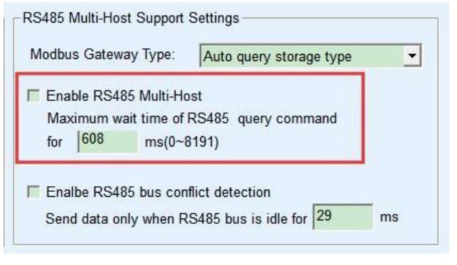
- Transfer Protocol (Modbus_TCP Protocol): A simple transparent converter will not have to do this. In this mode the device is forced to strip off the MBAP headers and add correct CRC checksums on-the-fly.
- Modbus Gateway Type (Auto Query Storage Type): Turns on Edge Caching, and separates the Gigabit Ethernet timing from the slow 9600 baud serial line to prevent polling crashes.
- RS485 Bus Conflict Detection: Implements physical FIFO queuing logic such that even if 5 different SCADA servers request data at the same time the RS485 bus will take them one after the other in the order they were requested with defined idle intervals (e.g. 20ms) to avoid electrical collisions.
Hardware Specification Summary Matrix
| Integration Challenge | Required Hardware Feature | The Valtoris Solution |
|---|---|---|
| MBAP / CRC Rejection | Active Protocol Translation | True Modbus RTU/TCP Bilingual Translation |
| SCADA Polling Crashes | Edge Data Caching | Storage Modbus Mode (Sub 5ms response) |
| Multi-Master Collisions | FIFO Queuing & Arbitration | Supports up to 30 concurrent TCP socket clients |
| VFD Noise & Ground Loops | Galvanic Isolation | 1.5kV - 3kV Opto-Isolation Standard |
Find Your Exact Port Density & Protection Level
Browse our complete Hardware Specification Matrix to match your exact channel count and opto-isolation requirements for seamless, industrial-grade SCADA integration.
View Hardware Specification Matrix →6. Field Integration FAQs: Beyond the Basics
Q1: Should I connect the RS485 shield ground to the Modbus Gateway?
Connect the shield to earth ground at ONE end only—typically at the master gateway inside the main control panel. If you connect the shield ground at both the gateway and the field device, you will inadvertently create a path for ground loop currents (as detailed in Section 5.2) to travel along the shield, which acts as an antenna for EMI and will severely disrupt communication.
Q2: If my Modbus TCP gateway has built-in 120-ohm termination DIP switches, do I still need to wire an external resistor at the field end?
Yes. Engaging the DIP switch on the gateway only terminates the "Master" end of the line. A proper daisy-chain topology requires termination at both absolute physical ends. You must still install a physical 120-ohm resistor across the A and B terminals of the furthest slave device on your field bus to completely eliminate signal reflections.
Q3: How can I tell if the data drop is caused by my SCADA software or a faulty serial bus?
Isolate the layers. First, bypass your SCADA entirely and use a standalone polling tool like ModScan32 or QModMaster from your PC to poll the gateway IP. If ModScan retrieves data perfectly, your SCADA polling rate is likely too aggressive (refer to the Polling Calculator above). If ModScan also times out, visually inspect the TX/RX LED indicators on the physical gateway. If TX blinks but RX remains dark, the issue is strictly on the RS485 physical wiring or slave device configuration.
Q4: Does the gateway support Modbus Broadcast (Slave ID 0)?
Yes, but with caveats. When a Modbus TCP client sends a request addressed to Unit ID 0, a standard gateway will translate this and broadcast it to all serial slaves. However, per the Modbus protocol standard, slave devices do not respond to broadcast messages (to prevent bus collisions). Therefore, your SCADA must not expect an acknowledgement for Broadcast writes, or it will falsely flag a timeout error.
Q5: Can I mix 4-wire RS422 and 2-wire RS485 devices on the same gateway port?
You cannot mix 2-wire (Half-Duplex) and 4-wire (Full-Duplex) devices on the same physical daisy-chain bus. However, if you select a Multi-Port Modbus Gateway, you will be able to configure port 1 as a 2-wire RS485 network and port 2 as a 4-wire RS422 network, collecting all the data to the SCADA system over one Ethernet IP.
