

The introduction of a wireless infrastructure to replace hundreds of meters of old RS485 communication wire is a fundamental shift in factory automation. New conduit over a factory floor with Variable Frequency Drives (VFDs), structural steel tanks, and high voltage motors is prohibitively expensive and disruptive to production. In these cases the best engineering choice (mathematically) is often to deploy a robust zigbee mesh network.
Zigbee technology, governed globally by the IEEE 802.15.4 standard, is a universally recognized protocol for low-power, self-healing wireless communications. Yet, the gap between consumer-grade Zigbee gear engineered for smart home lighting and true industrial deterministic communication is a chasm that frequently swallows deployment budgets. When critical Modbus RTU polling data is lost in the invisible 2.4GHz interference battlefield, the entire SCADA control loop fails, leading to ghost timeouts and blind operators.
This definitive engineering guide is designed to cut thru the consumer marketing hype. We will dissect how to physically bypass pervasive Wi-Fi interference, calculate precise RF link budgets, mitigate single points of failure (SPOF), and successfully bridge legacy RS485 field instruments to modern Modbus TCP SCADA networks using industrial-grade Zigbee serial converters.
2.4GHz RF Collision & Coexistence Analyzer
Over 70% of Zigbee deployment failures are caused by severe RF interference from existing factory IT infrastructure. Select your plant’s primary Wi-Fi channels below to calculate the safest deployment spectrum for your OT network.
The Reality Check: Industrial vs. Consumer Zigbee Hardware
A deadly but common mistake in operational technology (OT) design is to assume that a wireless protocol proven in a residential smart home is inherently ready for the factory floor. The standard defines a robust wireless language, but the physical hardware executing that language ultimately determines whether the network survives.
For example, consider a scenario where an engineer needs to remotely monitor a 4-20mA analog pressure transmitter or control a high-power 380V three-phase AC motor thru SCADA. A common misconception propagated by consumer IoT forums: a generic Zigbee node can directly talk to heavy industrial loads. In fact, the industrial zigbee router device (e.g., VT-ZIGBEE700 series) is strictly designed as a transparent serial data bridge. It does not have native Digital Output (DO) relays to drive 380V contactors, and does not natively ingest raw 4-20mA Analog Inputs (AI).
The right secure architectural approach is a modular hardware cascade: This means that your field sensor (4-20mA) or motor contactor must be wired first to a standard, industrially isolated RS485 Remote I/O Module. The I/O module is then connected to the industrial Zigbee serial converter via the RS485 output. The converter then transparently wraps the Modbus RTU data into the wireless network, functioning as a “invisible serial cable” back to the main server.
To survive in this harsh environment, the gateway hardware must possess physical specifications that consumer electronics simply cannot meet.
| Critical Parameter | Consumer/Light-Commercial Node | Industrial Zigbee Converter (e.g., VT-ZIGBEE700) |
|---|---|---|
| Operating Temperature | 0°C to 40°C (Causes thermal throttling and CPU lockups in unventilated panels) | -40°C to 85°C (Guarantees survival in outdoor cabinets and near heavy machinery) |
| Power Supply Input | 5V DC USB (Highly vulnerable to industrial voltage sags and transients) | 9~24V DC Terminal Block (Integrates directly with standard industrial PLC cabinet power) |
| Physical Enclosure | Plastic (Transparent to Electromagnetic Interference) | SECC Metal Chassis (Acts as a Faraday cage against VFD electrical noise) |
| Data Interfaces | Proprietary logic pins or consumer Bluetooth bridging | Isolated RS232, RS485/422, and RJ45 Ethernet |
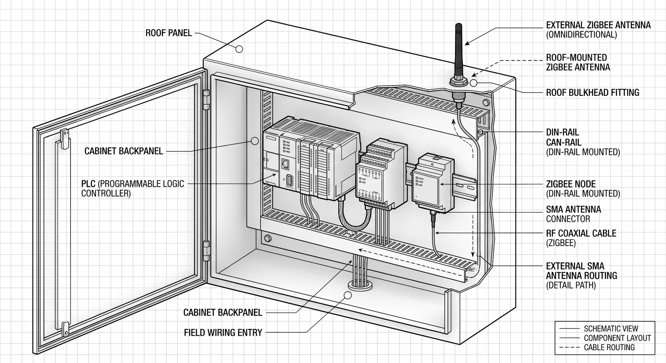
| Antenna Design | Internal PCB trace antenna (Completely blocks signals if placed inside a metal panel) | External SMA connector (Allows antenna mounting outside metal cabinets for maximum line-of-sight range) |
Calculating Link Budgets and the Zigbee Gateway Range
Marketing brochures often refer to maximum theoretical wireless ranges under ideal vacuum conditions. In practical reality, you would have to calculate the RF Link Budget to get your real zigbee gateway range. Any data packet must be transmitted at a power that, less path loss, plus antenna gains, is well above the receiver’s minimum sensitivity threshold to arrive uncorrupted at its destination.
The VT-ZIGBEE700 series operates in the 2.405GHz to 2.480GHz frequency range with 16 selectable channels using Direct Sequence Spread Spectrum (DSSS) modulation. DSSS does improve interference rejection, but the 2.4GHz wavelength has a hard time physically penetrating dense matter than sub-GHz frequencies.
An industrial Zigbee node transmitting at high power might achieve distances up to 2000 meters in a completely open field. However, forcing that same 2.4GHz signal to penetrate a standard 8-inch reinforced concrete wall will incur an immediate attenuation penalty of roughly -12dB to -15dB. Penetrating a solid steel bulkhead drops the signal entirely. This makes antenna elevation outside of control cabinets absolutely mandatory.
To overcome heavy attenuation in factory environments and maximize the effective zigbee gateway range, engineers must focus on Antenna Gain. Replacing a standard 2dBi omnidirectional “rubber duck” antenna with a high-gain directional Yagi antenna effectively focuses the RF energy into a tight beam, massively increasing penetration power along a specific corridor.
Surviving the 2.4GHz Battlefield: Wi-Fi Coexistence Strategies
The fundamental challenge of deploying wireless OT networks is that factory IT departments extensively deploy 802.11 b/g/n Wi-Fi access points across the exact same 2.4GHz frequency spectrum. Wi-Fi access points transmit at significantly higher power levels compared to standard nodes, easily “shouting over” critical telemetry data and causing massive packet collisions.
To resist ambient noise, the hardware utilizes CSMA-CA (Carrier Sense Multiple Access with Collision Avoidance). Before a node transmits, it “listens” to the channel to see if it is clear. If it detects heavy Wi-Fi traffic, the CSMA-CA algorithm forces it to back off and wait. If the channel is perpetually saturated, the node will eventually time out, dropping the Modbus payload entirely.
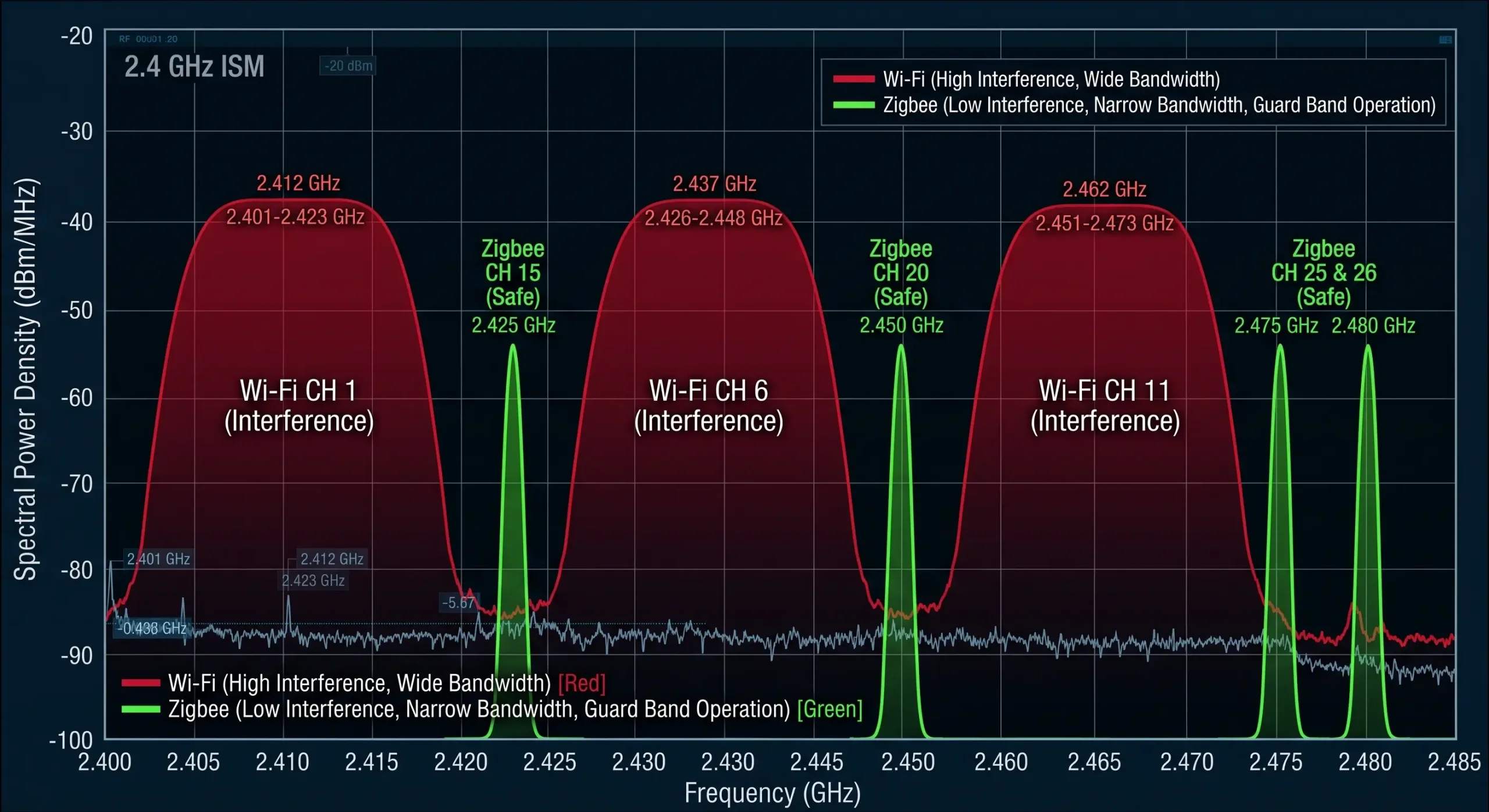
Standard Wi-Fi routers automatically select non-overlapping channels 1, 6, and 11. These wide 22MHz Wi-Fi channels completely envelop many of the narrower 2MHz Zigbee channels.
| Heavy Wi-Fi Traffic Detected On | Vulnerable Zigbee Channels (DO NOT USE) | Optimal Zigbee Channels (Safe Harbor) |
|---|---|---|
| Wi-Fi Channel 1 (2412 MHz) | 11, 12, 13, 14 | 15, 20, 25, 26 |
| Wi-Fi Channel 6 (2437 MHz) | 16, 17, 18, 19 | 15, 20, 25, 26 |
| Wi-Fi Channel 11 (2462 MHz) | 21, 22, 23, 24 | 15, 20, 25, 26 |
| Saturated (1, 6, & 11 all active) | Most of the 2.4GHz spectrum | Channel 15, 20, 25, or 26 (Fall in the narrow guard bands between Wi-Fi channels) |
By forcing your Coordinator to build its mesh exclusively on “Safe Harbor” channels—most notably Channel 26, which operates slightly above the primary Wi-Fi envelope—you can drastically reduce the background noise floor, minimizing CSMA-CA back-offs and dropping dropped packets to near zero.
Architecting the Mesh: Router Placement and Hop Limits
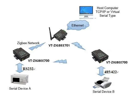
Engineers evaluating wireless topologies frequently ask: is zigbee a mesh network? The answer is yes, natively. Unlike point-to-point radios that fail if a single line-of-sight is blocked, mesh network zigbee topologies utilize advanced routing protocols. The VT-ZIGBEE700 series explicitly supports point-to-point, star, tree, and mesh architectures.
In a true mesh, nodes continuously monitor link quality. If a large forklift parks in front of Node B, blocking its path to the gateway, the zigbee mesh networking algorithm dynamically re-routes the data through Node C. This self-healing capability is what makes it viable for industrial automation.
Running out of Network IDs is a frequent issue when designing large scale meshes The VT-ZIGBEE700/701 series supports 16 selectable wireless channels. It allows the engineers to freely configure up to 65,535 independent Network IDs (0000~FFFF). This enables massive scalability across sprawling plant floors with no chance of cross-network interference.
However, mesh routing physics dictate strict deployment protocols based on distinct node roles.
| Device Role | Function in the Network | Power Requirement | Routing Capability |
|---|---|---|---|
| Coordinator | Initializes the PAN (Personal Area Network), selects the RF channel, and bridges wireless data to the Ethernet/TCP network. | Mains / Continuous (9-24V DC) | Yes (Root Node) |
| Router | Acts as an active repeater. Receives data from distant nodes and forwards it toward the Coordinator. Maintains routing tables. | Mains / Continuous (9-24V DC) | Yes (Mesh Backbone) |
| End Device | Sensors that sleep to conserve battery. Wakes up, transmits data to its parent Router, and goes back to sleep. | Battery / Solar | No (Endpoint only) |
The Law of Deployment Sequencing
When executing a proper zigbee configuration, sequencing is critical. You cannot simply plug everything in at once. In any professional zigbee tutorial, you will find that the order of operations dictates the stability of the routing tables.
To master how to setup zigbee networks effectively, follow this sequence: You must first install and power on the Coordinator. Second, you must install and power on all constantly powered Routers (the converters wired to your 24V PLC cabinets). You must allow the network several minutes to achieve “routing convergence”—the process where routers broadcast link-status messages, discover their optimal RF neighbors, and build the mesh routing tables.
Only after the robust router backbone is established should you power on battery-operated End Devices. If you power everything on simultaneously during your initial zigbee setup, End Devices may attempt to bind to weak, distant routers before the optimal local routers are fully online, leading to fragile, sub-optimal data paths.
Addressing the Elephant in the Room: Coordinator Single Point of Failure (SPOF)
Browse any industrial automation forum, and the first critique of wireless networks is always the same: “The Coordinator is a Single Point of Failure (SPOF). If the central gateway dies, the entire mesh collapses.”
This is a completely valid engineering concern. The protocol standard dictates that a network can only have one active Coordinator at a time. It establishes the PAN ID and manages security keys. If a power surge destroys the Coordinator, the Routers and End Devices become orphaned, unable to pass data to the SCADA server.
While true “Hot Standby” (Active-Active) clustering is not native to the basic protocol, OT engineers bypass this vulnerability through strict architectural planning. Consumer hubs are unrecoverable black boxes; industrial gateways are configurable state machines.
| Mitigation Strategy | Implementation Method | Recovery Time Objective (RTO) |
|---|---|---|
| Cold Spare Pre-Provisioning | Keep a secondary Gateway pre-configured with the exact same PAN ID, Channel, and MAC address logic powered off in the cabinet. If the primary fails, swap cables and power on. | < 5 Minutes (Manual swap) |
| Network Micro-Segmentation | Instead of one massive 150-node network, deploy three separate Coordinators on different channels, each managing 50 nodes. A gateway failure only impacts 33% of the plant. | Instant (Partial isolation limit) |
| Upstream Hardware Watchdogs | Utilize industrial gateways with built-in silicon watchdogs. If the processor hangs due to a transient spike, the hardware automatically cuts power and reboots the radio chipset. | < 30 Seconds (Autonomous) |
Bridging the OT Gap: From Zigbee Wireless to Modbus TCP PLCs
Getting the RF signal from point A to point B without collision is a triumph of physics, but the data is useless if it remains trapped in the air. The data must be translated into a format that a modern SCADA server or PLC can ingest natively over Ethernet.
This is where the Zigbee to Ethernet Gateway acts as the critical bridge. The VT-ZIGBEE701 operates as an industrial device server, capturing the wireless packets—which contain the raw Modbus RTU serial payloads originally sent by the remote nodes—and encapsulating them into TCP/IP packets.
To facilitate this, the VT-ZIGBEE701 features a built-in zigbee web server for configuration. By accessing the gateway’s IP address (the factory default is 192.168.1.200) through a standard browser and entering the default password (123456), engineers can easily configure the static zigbee ip, subnet mask, and designate the device to operate in TCP Server, TCP Client, or UDP mode.
The VT-ZIGBEE701 internally bridges a Zigbee radio engine to an Ethernet module. The technical manual strictly warns that the Network setting’s baud rate MUST identically match the Zigbee radio’s baud rate (which defaults to 38400bps). If you adjust the RF baud rate to match your PLC but forget to update the network module’s baud rate, the internal bridge breaks.
Pro-Tip: If you ever lock yourself out of the network, dialing the physical CFG switch on the back panel to “ON” will force the device into config mode and restore the IP to a fallback address of 192.168.1.254.
The Virtual Serial Port Solution for Legacy SCADA
Many legacy SCADA software packages or older PLCs are hardcoded to look for physical COM ports (e.g., COM3) and cannot naturally interface with an IP address over an Ethernet network. Upgrading the SCADA software to support Modbus TCP might cost thousands of dollars in licensing fees and downtime.
Industrial gateways circumvent this using Virtual Serial Port software. The VT-ZIGBEE701 is equipped with the Windows virtual serial port and device managing tool, Vircom. Vircom runs on the central SCADA PC as a background service and creates a “phantom” COM port at the OS level. When the SCADA software opens COM2 to send a Modbus query, the software intercepts that data, packages it over the LAN to the Gateway’s assigned zigbee ip, which then broadcasts it over the wireless network. The remote flow meter replies, and the data flows seamlessly back into the software exactly as if a 500-meter copper wire were plugged into the back of the computer.
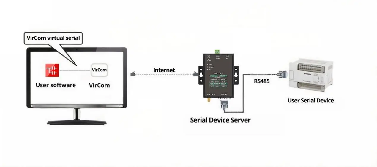
Field engineers hate modifying their laptop’s IPv4 settings just to match a gateway’s factory default subnet. The included Vircom management utility bypasses this completely. It can discover and configure devices across different network segments. You can remotely assign IP addresses, adjust serial baud rates (from 1200 to 115200bps), and configure Modbus parameters without ever putting your PC on the same IP subnet as the gateway.
Deep Dive: Direct Modbus TCP to RTU Protocol Conversion
If your PLC is modern, you don’t need virtual ports. You can configure an industrial Gateway to utilize an active Modbus TCP<->RTU transfer protocol setting. This is not simple “transparent forwarding”—this is active packet dissection.
In this mode, the gateway listens on standard TCP port 502. Let’s look at exactly what happens under the hood when a modern PLC sends a request to read holding registers:
00 01 00 00 00 06 05 03 00 0A 00 02(Transaction ID: 00 01 | Protocol: 00 00 | Length: 00 06 | Unit ID/Slave: 05 | Function: 03 | Address: 00 0A | Quantity: 00 02)
2. Gateway intercepts and strips MBAP header, adds CRC for serial:
05 03 00 0A 00 02 E5 4C(Slave ID: 05 | Function: 03 | Address: 00 0A | Quantity: 00 02 | CRC-16: E5 4C)
3. Gateway broadcasts payload wirelessly to Remote Node.
4. Node outputs RTU frame via RS485. Slave replies. Gateway reverses process.
This active conversion is the ultimate, deterministic bridge between the rugged, noisy physical world of legacy serial automation and the high-speed, IP-routed networks of the modern control room.
Frequently Asked Questions (FAQ)
If the factory loses power and hundreds of nodes boot up simultaneously, will the network crash from a “broadcast storm”?
My PLC is locked inside a sealed stainless-steel control cabinet. How does the wireless signal escape the Faraday cage?
Can I use a wireless network to poll 50 Modbus devices every 50 milliseconds?
Will the heavy Electromagnetic Interference (EMI) from large Variable Frequency Drives (VFDs) disrupt the 2.4GHz wireless signal?
If the main Coordinator burns out, how quickly can a backup gateway take over the routing?
How can I visually confirm if my Modbus data is successfully crossing the wireless bridge?
Need Help Architecting Your Mesh?
Stop fighting Wi-Fi interference and Modbus timeout errors. Let our engineering team help you calculate your link budget, configure your channels, and design a bulletproof mesh network for your RS485 equipment.
