

You probably have seen the word “ZigBee” stamped on smart home hubs, or heard it casually tossed around in IoT architecture meetings by IT professionals. If you’re an automation engineer or an operational technology (OT) system integrator, you’re probably asking yourself a much more practical question: What is ZigBee technology? Is it just a high-tech version of Wi-Fi? And more importantly, can I trust it to replace the hardwired RS485 communication lines on my noisy, metal-laden factory floor?
Let’s cut through the consumer marketing noise. Here is the definitive, no-nonsense answer: ZigBee is an industrial-grade wireless protocol engineered specifically for machine-to-machine (M2M) communication. It is designed for devices that need to transmit critical telemetry data reliably, consume micro-amps of power, and automatically form a self-healing mesh network without relying on a central router.
That is the high-level summary. But what happens when you take ZigBee out of a climate-controlled living room and drop it into a harsh industrial environment filled with Variable Frequency Drives (VFDs), thick steel control cabinets, and saturated corporate Wi-Fi signals?
In this all-inclusive engineering guide, we’ll demystify the physical and network layers of ZigBee, examine the crippling impact of 2.4 GHz interference and expose the hardware tactics needed to effectively connect wireless field data directly into your Siemens or Allen-Bradley PLCs.
Table of Contents
- Quick Reality Check: Is ZigBee Still Relevant in 2026?
- The Protocol Stack: How ZigBee Actually Works
- The 2.4 GHz Problem: Surviving Wi-Fi Interference
- Signal Penetration: Metal Cabinets vs. 2.4 GHz Waves
- Bridging the IT/OT Divide: Getting ZigBee Data into Your PLC
- Network Capacity and Payload Limits: Engineering the Edge
- Step-by-Step: Commissioning a ZigBee-to-Ethernet Gateway
- Consumer vs. Industrial Grade: Specifying the Right Hardware
- Expert FAQ: Industrial ZigBee Implementation
Quick Reality Check: Is ZigBee Still Relevant in 2026?
As 5G cellular networks and Wi-Fi 6 are being deployed at a rapid pace, one misconception among rookie integrators is that low-bandwidth protocols such as ZigBee are going away. But in terms of examining the Total Cost of Ownership (TCO) of massive sensor deployments, the global macroeconomic data paints a very different picture.
| Market Metric | Verified Data Value |
|---|---|
| Global ZigBee market size (2025) | USD 5.2 billion |
| Projected Market Size by 2035 | USD 9.3 billion |
| Annual Compound Growth Rate (CAGR) | 6.1% consistent growth |
| Industrial & Automation Segment Share | 34.6% (The single largest adopting sector) |
Source Data: Future Market Insights, 802.15.4/ZigBee Global Market Report.
ZigBee isn’t vanishing; it is dominating the OT landscape. Why? Because 5G incurs recurring monthly SIM card data fees, and Wi-Fi consumes far too much power for remote sensors. For facility-wide, license-free, and operational expense (OpEx) free telemetry, ZigBee remains an undisputed standard.
The Protocol Stack: How ZigBee Actually Works
To truly understand how does ZigBee work, engineers must look at the underlying protocol stack. ZigBee is not built from scratch; it is constructed on top of the IEEE 802.15.4 standard. This foundational IEEE standard defines the Physical (PHY) and Media Access Control (MAC) layers for Low-Rate Wireless Personal Area Networks (LR-WPANs).
At the physical layer, ZigBee utilizes Direct Sequence Spread Spectrum (DSSS) modulation. DSSS is critical for industrial environments because it spreads the radio signal over a wider frequency band, making the transmission highly resistant to narrow-band electromagnetic interference (EMI) generated by heavy machinery and motors.
The Mechanics of a Self-Healing Mesh Topology
Standard Wi-Fi operates on a Star topology. Every laptop, phone, or AGV robot must maintain a direct line of communication to a central Access Point (AP). If a forklift parks in front of the AP, or if the router experiences a hardware failure, every device connected to it goes dark.
ZigBee operates on a true Mesh Topology (though it also supports point-to-point, star, and tree structures). In a mesh network, wireless nodes do not just talk to the central gateway; they talk to each other. If Node A cannot reach the main control room because a steel blast door was closed, it dynamically routes its payload through Node B, which passes it to Node C, and finally to the gateway. If Node B loses power, the network algorithms instantaneously recalculate a new path. This “self-healing” attribute provides the redundancy required for critical SCADA systems.
The Strict Roles Within a ZigBee Network
Unlike Bluetooth (BLE) where devices largely act as peers, an industrial ZigBee network requires strict hardware roles to organize the mesh effectively.
| ZigBee Role | Network Function & Responsibility | Hardware Power Requirement |
|---|---|---|
| Coordinator (Gateway) | The core intelligence of the network. It initializes the mesh, assigns network IDs (0000~FFFF), manages security encryption keys, and acts as the bridge translating data to TCP/IP. (Only one per network). | Grid Powered (Must be always on) |
| Router (Repeater) | The backbone of the mesh. Routers accept data from other nodes and pass it along the chain. They extend the physical range and provide the alternate routing paths essential for self-healing. | Grid Powered (Must be always on) |
| End Device (Sensor Node) | The absolute edge. Collects raw telemetry (e.g., flow, temperature). To conserve power, it sleeps heavily and only wakes up to transmit bursts of data to a parent Router or Coordinator. It cannot route traffic for others. | Battery or Solar (Ultra-low power) |

The 2.4 GHz Problem: Surviving Wi-Fi Interference on the Factory Floor
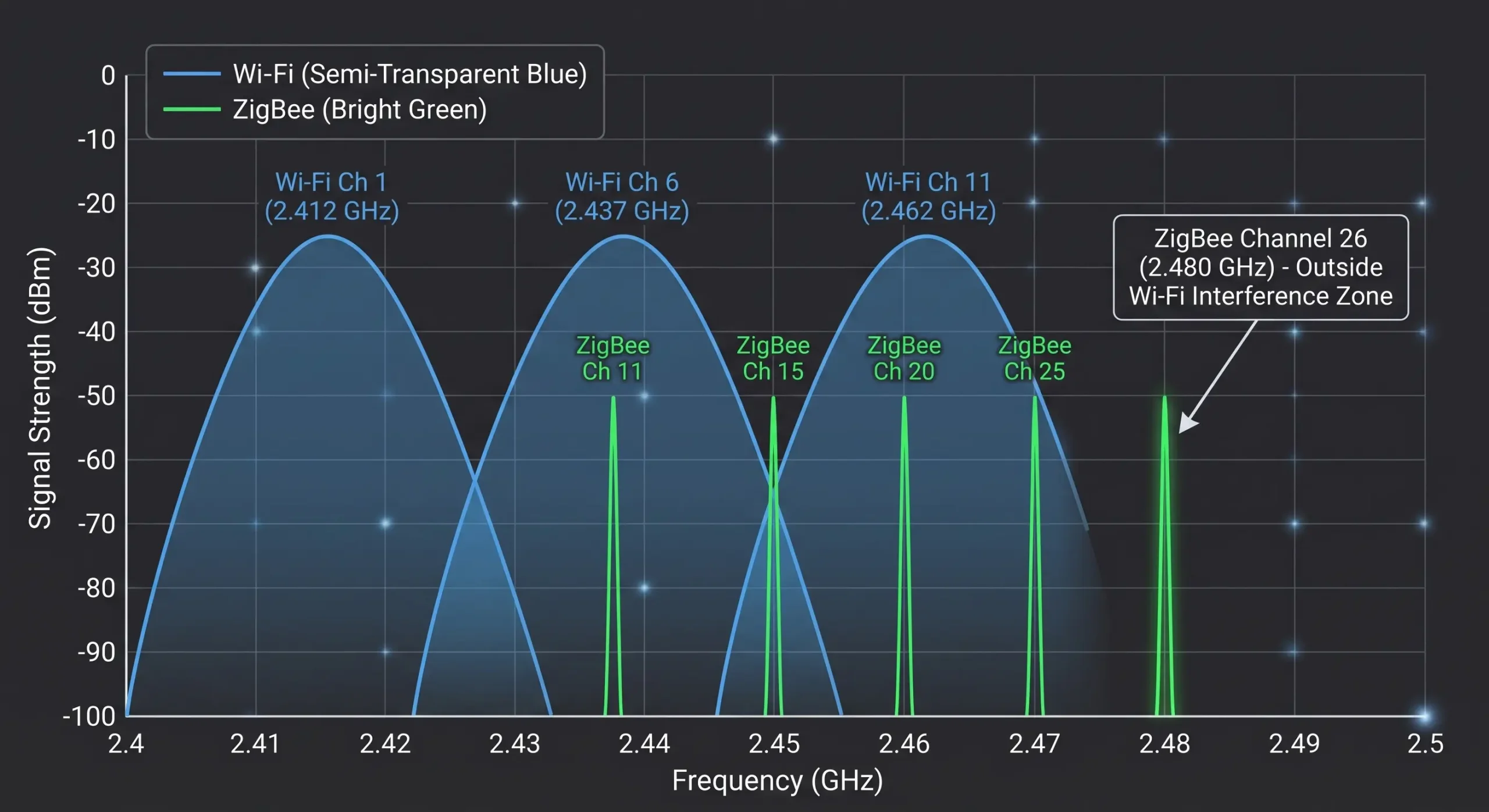
Now we must address the most significant engineering hurdle. ZigBee operates globally on the license-free ISM band, specifically from 2.405 GHz to 2.480 GHz. This is the exact same spectrum saturated by corporate Wi-Fi (802.11 b/g/n) and Bluetooth networks.
When novice integrators install cheap wireless modules, they frequently complain of random packet loss and communication timeouts. The root cause is rarely the physical distance; it is Channel Access Failure. ZigBee utilizes an anti-collision mechanism known as CSMA-CA (Carrier-Sense Multiple Access with Collision Avoidance). Before a ZigBee transmitter sends data, it physically “listens” to the airwaves. If a nearby corporate Wi-Fi access point is blasting a massive 40MHz video stream, the ZigBee node detects the noise, assumes the channel is occupied, and backs off. If the Wi-Fi traffic doesn’t subside, the ZigBee node eventually times out and drops the telemetry packet.
Standard Wi-Fi monopolizes the spectrum on three wide channels 1, 6, and 11. ZigBee, however, divides the 2.4 GHz spectrum into 16 narrow (but separate) channels (11 thru 26). With a simple RF site survey to know the Wi-Fi channels present in your factory, you can manually lock your ZigBee hardware to the “gap channels”—, specifically Channels 15, 20, 25, or 26. This physically isolates your telemetry data from the IT network’s noise floor, virtually eliminating dropped packets.
| IT Wi-Fi Setup (Interference Source) | Wi-Fi Center Frequency | Recommended ZigBee Channels (The Safe Zone) |
|---|---|---|
| Wi-Fi Channel 1 | 2412 MHz | 15, 20, 25, 26 |
| Wi-Fi Channel 6 | 2437 MHz | 11, 25, 26 |
| Wi-Fi Channel 11 | 2462 MHz | 15, 20 |
| Multiple APs (Ch 1, 6, & 11 active) | Full Spectrum Saturation | Channel 26 Only (Safest universal channel) |
Signal Penetration: Metal Cabinets vs. 2.4 GHz Waves
Assuming that you have solved the channel interference issue, the next physical limitation is the deployment environment. In the open air, industrial ZigBee devices with 25dBm transmission power and -105dBm receiving sensitivity can reach communication distance of 2000 meters. But the reality of the shop floor is much harsher.
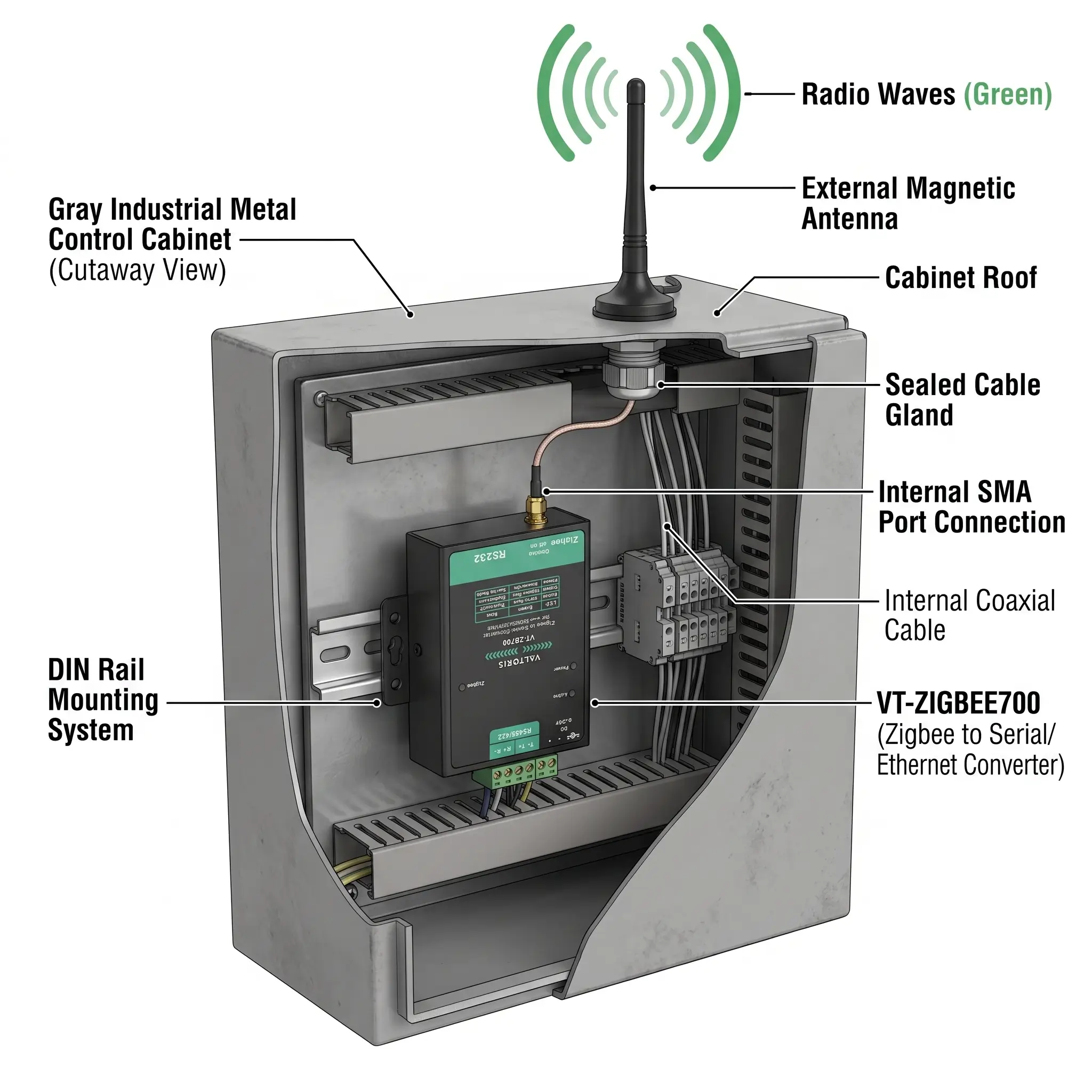
Short radio wavelengths of 2.4 GHz used by high frequency signals are easily reflected and absorbed by dense materials. For industrial automation, Programmable Logic Controllers (PLCs) and variable frequency drives are a must, inside thick steel control cabinets. If you put a wireless module with a PCB antenna inside this cabinet and close the steel door you have created a perfect Faraday cage. The RF signal will internally reflect, and attenuate quickly, leading to complete communication blackout.
This physical reality dictates that industrial wireless implementations cannot rely on internal antennas. Authentic industrial hardware is equipped with an external SMA male head antenna connection. The right engineering solution is to drill a bulkhead hole in the top of the steel enclosure, run an RF coaxial pigtail thru it, and mount a high-gain magnetic suction cup antenna to the outside of the cabinet. This protects the internal circuitry from dust and electrical noise, but provides the antenna with a clear line-of-sight across the factory floor.
| Obstacle Material | 2.4 GHz ZigBee Penetration Capability | Engineering Mitigation Strategy |
|---|---|---|
| Drywall / Wood (Office) | Excellent (Minimal attenuation) | Standard deployment; nodes act as mesh repeaters. |
| Concrete Blast Walls | Poor (Heavy absorption) | Rely on Mesh routing; place Router nodes at doorways/corridors to bend the signal around the obstacle. |
| Steel Control Cabinets | Zero (Total Faraday Shielding) | Mandatory: Utilize external SMA antenna interfaces to mount the radiating element outside the box. |
Bridging the IT/OT Divide: Getting ZigBee Data into Your PLC
This is the critical juncture where many “IoT pilot projects” fail to reach production. It is relatively easy to make two wireless nodes flash their LEDs at each other. However, raw wireless packets are entirely useless to an automation system. Ultimately, the telemetry data collected from remote flow meters or sensors must be parsed and fed into the registers of a Siemens S7, Allen-Bradley ControlLogix, or an overarching SCADA historian.
You cannot simply plug a ZigBee receiver into the ethernet port of a PLC. You require a dedicated, intelligent hardware translation layer that bridges the Operational Technology (OT) serial world with the Information Technology (IT) IP world.
The Protocol Translation Architecture
Let’s examine a proven architecture using dedicated industrial converters, specifically detailing how the Modbus protocol is handled across the airwaves.
- Data Ingestion at the Edge: A field device outputs data via RS485 using the Modbus RTU protocol. A serial-to-ZigBee node, such as the VT-ZIGBEE700, ingests this serial data through its terminal blocks, packages the Modbus payload into an IEEE 802.15.4 wireless frame, and broadcasts it.
- Central Reception: A coordinator gateway device, such as the VT-ZIGBEE701, is physically connected to the factory’s Ethernet LAN. It receives the wireless payloads from dozens of field nodes.
- On-the-Fly Protocol Conversion: PLCs and SCADA systems operate primarily on Ethernet-based protocols. The VT-ZIGBEE701 possesses the internal processing power to automatically execute
Modbus TCP <-> RTUconversion. The gateway strips the wireless headers, takes the raw RTU serial payload, wraps it in a TCP/IP header, and serves it on standard Port 502.
The wireless network is totally transparent to the Siemens or Rockwell PLC. The PLC just sends a normal MB_CLIENT (Modbus Client) command to the IP address of the Gateway. The SCADA software polls the gateway same as it would any hard-wired remote I/O rack.
| Communication Stage | Hardware Device | Active Protocol / Interface |
|---|---|---|
| 1. Field Sensor Output | Flow Meter / Sensor | RS485 Serial (Modbus RTU) |
| 2. Wireless Transmission | VT-ZIGBEE700 Node | 2.4GHz IEEE 802.15.4 / DSSS |
| 3. Network Aggregation | VT-ZIGBEE701 Gateway | Ethernet RJ45 (10/100M LAN) |
| 4. PLC / SCADA Ingestion | Siemens / AB PLC / PC | TCP/IP (Modbus TCP) via Port 502 |
The Legacy SCADA Solution: Virtual COM Ports
What if your central monitoring computer relies on 20-year-old SCADA software that absolutely refuses to accept IP addresses, insisting instead on reading from hardware “COM1” or “COM2”?
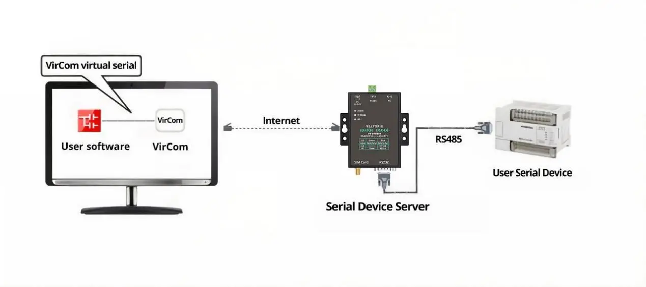
Industrial gateways solve this via Virtual Serial Port emulation. Using specialized management software like the Vircom Configuration Utility, engineers can scan the local network to find the gateway (e.g., at default IP 192.168.1.200) and bind it to a newly created virtual port, such as COM2. The legacy software opens this virtual “COM2”, and the Vircom driver intercepts the serial commands, wraps them in TCP/IP, and sends them across the Ethernet LAN to the ZigBee Gateway, which then fires them wirelessly to the end device. This enables total modernization of the physical infrastructure without rewriting a single line of legacy software code.
Network Capacity and Payload Limits: Engineering the Edge
Before deploying a wireless telemetry network, system integrators need to be mindful of the strict physical and data constraints of the protocol. ZigBee is not meant for moving large files; it is designed for dense, low-bandwidth telemetry.
Addressing and Network Density
A major advantage of ZigBee over standard Bluetooth is its huge addressing capacity. In an industrial ZigBee network the Network IDs can be in the range 0000 to FFFF (hex). This allows 65,535 different network identifiers to be given. In a dense industrial park you can run multiple independent ZigBee mesh networks side by side, without crosstalk, just by giving each process cluster a different Network ID.
Maximum Packet Size and Modbus Constraints
Engineers need to take into account the maximum transmission unit (MTU) when routing Modbus RTU packets over the air. In industrial Zigbee converters the Max Packet Size to 100 bytes.
A PLC might send a single Modbus request for 100 holding registers . This will be larger than the 100 byte limit for radios , and the packet will be fragmented or not sent at all . Engineers should modify the PLC polling logic to poll smaller chunks of data (e.g. 20 to 30 registers per poll) so that the payload fits neatly in a single IEEE 802.15.4 frame; zero packet loss and no bus collisions.
Step-by-Step: Commissioning a ZigBee-to-Ethernet Gateway
To fully demystify the IT/OT integration process, let’s examine how an engineer actually configures a central Ethernet gateway (like the VT-ZIGBEE701) to pass data to a SCADA network.
- Network Discovery: The gateway is connected to the local LAN. Engineers utilize management software (such as the Vircom utility) to scan the subnet and discover the device MAC and current IP.
- Addressing the Gateway: Within the utility, the IP Mode is set to Static. The gateway is assigned a dedicated IP Address, Subnet Mask, and Gateway matching the corporate LAN.
- Selecting the Work Mode: To allow a SCADA server to initiate the connection, the gateway is set to TCP Server mode. The listening port is typically defined as Port 502 (the standard for Modbus TCP).
- Protocol Conversion: Under the ‘Transfer Protocol’ settings, the engineer selects
Modbus TCP <-> RTU. This enables the onboard processor to actively strip TCP headers and convert the payload for the downstream serial nodes. - Link Integrity (Keep Alive): To prevent IT firewalls from closing idle sockets during periods of inactivity, the Keep Alive Time is configured. The device will automatically send TCP heartbeats to the server at the defined interval, guaranteeing the TCP link remains valid.
Consumer vs. Industrial Grade: Specifying the Right Hardware
When procurement teams view the bill of materials for a wireless retrofit, there is often a temptation to purchase $30 smart home ZigBee modules and attempt to adapt them for factory use. In an industrial environment, this is a catastrophic operational risk.
Consumer devices are built for steady 22°C (72°F) environments, clean USB power, and minimal electromagnetic interference. When placed near a 500HP motor drive, consumer microcontrollers will lock up due to ground loops or voltage spikes. When subjected to winter temperatures inside an outdoor enclosure, the consumer-grade oscillators will drift, causing complete loss of radio synchronization.
| Critical Specification | Consumer Grade (Smart Home) | Industrial Standard (e.g., VT-ZIGBEE Series) |
|---|---|---|
| Operating Temperature | 0°C to +40°C | -40°C to +85°C (Survives severe freeze & heat) |
| Power Supply Design | 5V USB / AA Batteries | 9~24V DC wide-voltage input via industrial terminal blocks |
| Receiver Sensitivity | -90 dBm | -105 dBm (Ensures connection through thick walls) |
| System Reliability | Basic pairing logic | Hardware Watchdog, Keep Alive Time (Heartbeats), Reconnect intervals |
| Physical Enclosure | Flimsy plastic casing | Anti-radiation SECC board / Metal housing for EMI shielding |
Real industrial hardware is defined by its robustness. Take the VT-ZIGBEE701 as an example, which adopts the anti-radiation SECC metal board to physically prevent EMI, as well as critical software protections. For example, it uses a configurable ‘Reconnect Time’ setting. If the forklift temporarily breaks the radio path, causing a TCP disconnect, the gateway does not just crash, but actively buffers data and attempts to reestablish the connection based on the timed parameters that are configured by the engineer. This ensures 24/7 uptime without needing a technician to physically reboot the hardware.
Download the VT-ZIGBEE700 & 701 User Manual & Architecture Guide
No more guessing TCP/RTU conversion and struggling with Wi-Fi interference. Download the full Engineering Guide with RS485 wiring diagrams, Vircom virtual COM port configuration steps, and TCP client/server setup instructions.
Request Your Free Technical Manual
Expert FAQ: Industrial ZigBee Implementation
How do I handle PLC communication timeout errors when ZigBee mesh hops add latency?
Can I run ZigBee serial converters inside explosion-proof (Ex-d) enclosures?
What happens to industrial serial data packets if the ZigBee link temporarily disconnects?
Why choose ZigBee over Industrial Bluetooth (BLE) or Wi-Fi for RS485 replacement?
How to integrate ZigBee Modbus TCP data into Siemens TIA Portal?
Modbus TCP <-> RTU protocol conversion. In TIA Portal, you simply call the standard MB_CLIENT block, point the IP address to the ZigBee Gateway, and assign Port 502. The SCADA software polls the gateway just as it would any hardwired remote I/O rack.