
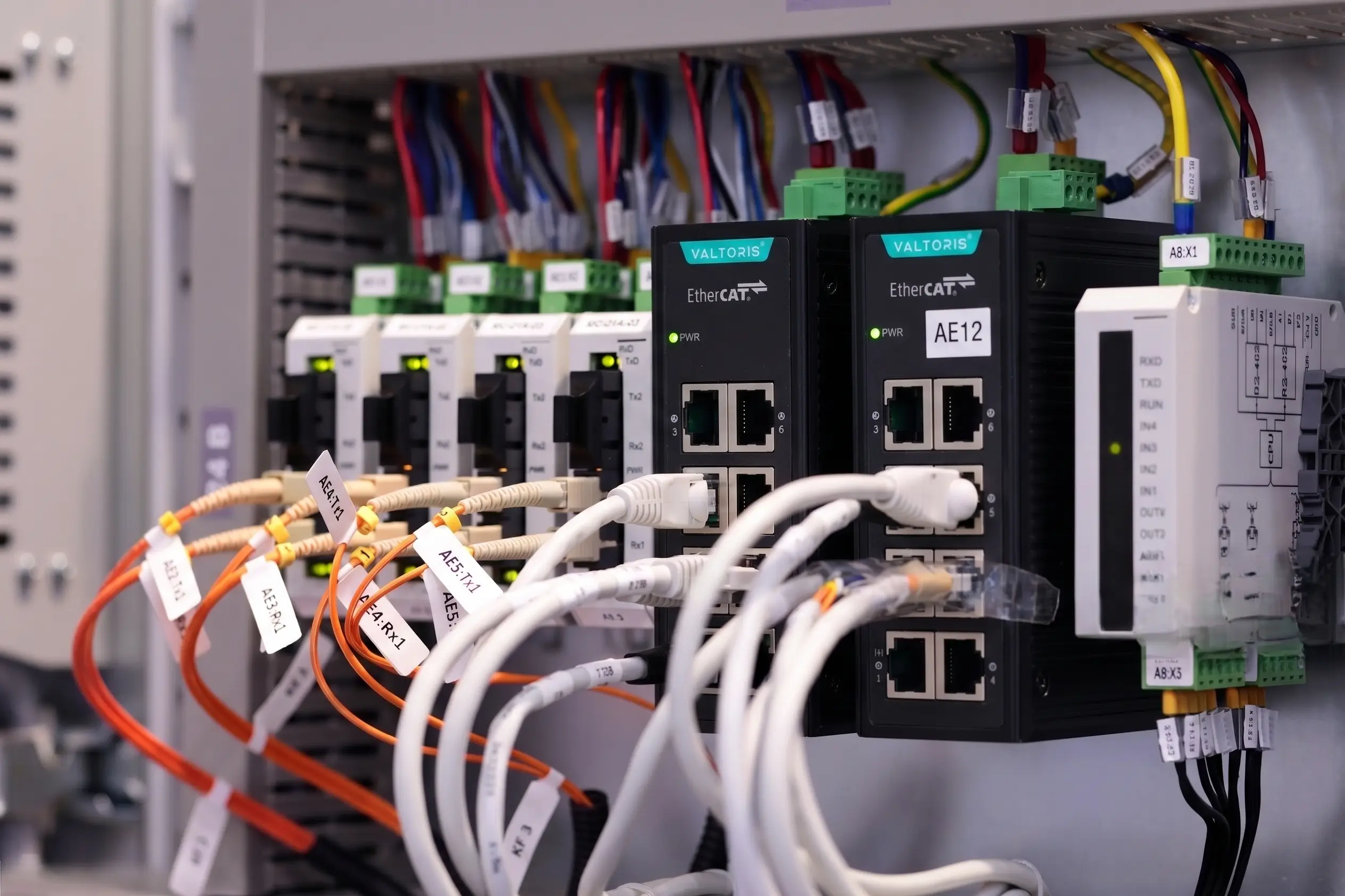
In simple terms, an EtherCAT topology is the physical wiring layout used to connect your main controller (PLC) to field devices like servo drives, remote I/O modules, and sensors. Unlike older industrial buses that force you into a single rigid wiring style, EtherCAT supports four flexible network structures: Line (Daisy-Chain), Star, Tree, and Ring (Cable Redundancy) topologies.
However, wiring an EtherCAT network topology comes with one major catch: it does not behave like standard office Ethernet. Standard two-port slaves only chain in a straight line, so if you need to branch your cables into a star or tree, you’ll need a specialized EtherCAT junction slave instead of a standard IT Ethernet switch. We’ll look at how each topology works, when and where to make choices, and how to wire your cabinet without dropping a frame.
This engineering guide breaks down the complete physical layer architecture—jump directly to a section below or test fault isolation in the interactive simulator:
- 1. Line, Star, Tree & Ring Topologies Explained (with Hot Connect)
- 2. How It Works Underneath: Physical Line vs. Logical Ring
- 3. Standard Ethernet Switch vs. Dedicated ESC Junction
- 4. The 4 Golden Rules of Wiring (Ports, Cables, 100m Limit & Grounding)
- 5. Field Troubleshooting: WKC, Lost Links & CRC Errors
Line vs. Star/Tree vs. Ring: Choosing the Right EtherCAT Topology
Because EtherCAT supports up to 65,535 slave nodes per network segment without cascaded switch limits, the machine’s mechanical layout should dictate your network architecture—not the other way around. Evaluating criticality and modular maintenance requirements determines which topology fits your machine.
| Topology Type | Hardware Needed | Fault Tolerance & Isolation | Best-Fit Machine Application |
|---|---|---|---|
| Linear (Daisy-Chain) | Zero extra junctions (Slave IN to OUT) | Low: Any single power loss or broken wire drops all downstream nodes. | Compact, fixed-frame single machines where all drives share one cabinet power supply. |
| Star / Tree Topology | 1-In-2-Out (T-Tap) or 1-In-5-Out (Star) ESC Junction | High (Branch Isolation): A severed drop-line or powered-off station is bypassed automatically. | Multi-station cells, robotic tool changers (ethercat hot connect), AGVs, and modular optional stations. |
| Cable Redundancy (Ring) | 2nd Ethernet port on Master PLC | Maximum: Survives a complete main trunk cable cut by feeding frames from both ends. | Continuous process plants, tunnel boring machines, and high-availability power infrastructure. |
1. EtherCAT Line Topology (Bus / Daisy-Chain Structure)
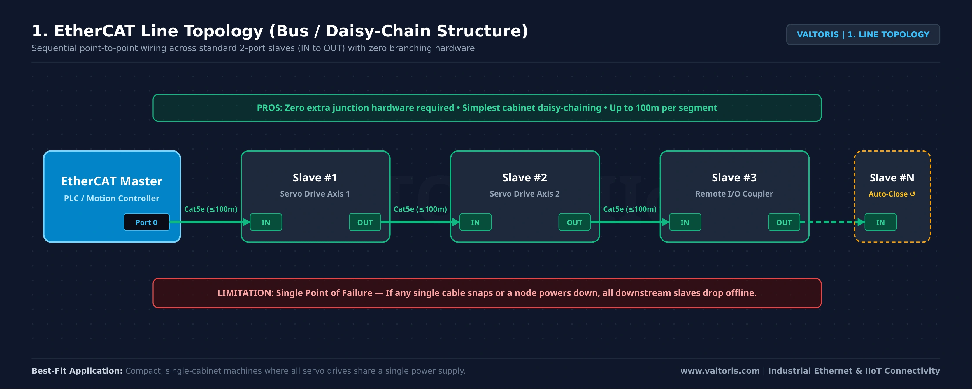
The most basic EtherCAT network topology is the line topology (or bus or daisy-chain topology). Most EtherCAT slaves have two RJ45 ports: an IN port that receives frames from upstream, and an OUT port that sends the frame downstream to the next device. But two recurring nightmares plague machine builders with a pure daisy-chain:
- Drag-Chain Cable Fatigue on Moving Gantry: A flexing cable on a moving gantry will fail, breaking the entire daisy-chain return path and taking down unrelated safety I/O and HMI panels downstream.
- Optional Machine Modules & Tool Changers: Most modern machines come with robotic EOATs that are capable of swapping out grippers mid cycle, or optional inspect stations which only ship on some customer orders (unplugging a node in a linear chain kills the entire bus).
2. EtherCAT Star Topology (Centralized Multi-Port Branching)
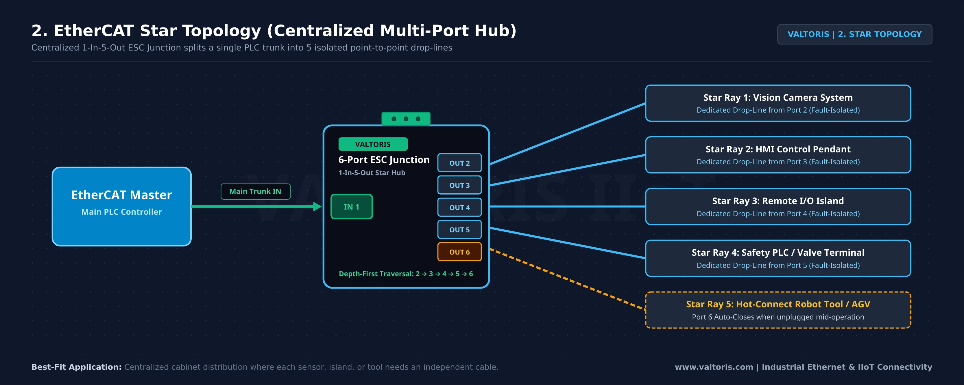
In an ethercat star topology, a multi-port ethercat junction slave acts as a central distribution hub. A compact DIN-rail ESC junction can be installed to split a single main trunk from the PLC into multiple individual drop lines that radiate out to individual servos, vision cameras, or remote I/O islands. For localized T-tap drop lines, a 1-In-2-Out module is available, while a 1-In-5-Out hub is offered for central cabinet distribution.
3. EtherCAT Tree Topology & EtherCAT Hot Connect
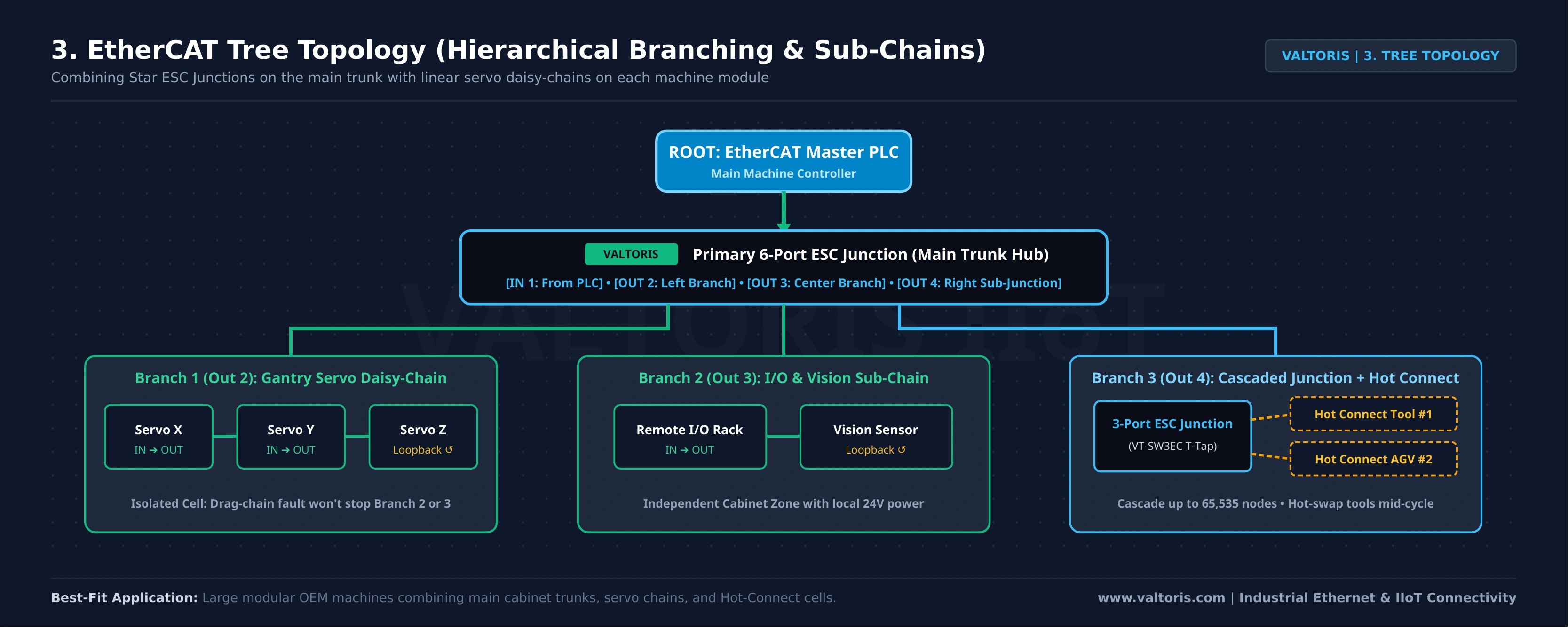
The EtherCAT tree topology is a combination of linear daisy-chains and star junctions. It is a multi-layered hierarchy with the master as the root, the junctions as the trunk and the short servo chains as the branches. Each moving gantry or optional workcell has its own isolated drop line. EtherCAT Hot Connect groups in the master software allow stations attached to the junction’s output ports to be powered down, unplugged or hot-swapped during live production without causing a master bus fault.
Hardware vs. Software Hot Connect Responsibilities
It is important to mention that an ESC junction provides the physical layer port isolation required for Hot Connect, but hardware alone is only half the setup. The junction handles the physical branching, while your PLC programmer still needs to configure “Hot Connect Groups” in the EtherCAT master software to prevent bus faults when unplugging tools.
Engineering Note: For actual panel builds, designers typically deploy compact DIN-rail modules like the Valtoris VT-SW3EC (3-port) for localized drop-lines, or the VT-SW6EC (6-port) for central cabinet distribution to ensure physical layer isolation.
4. EtherCAT Ring Topology (Cable Redundancy Structure)
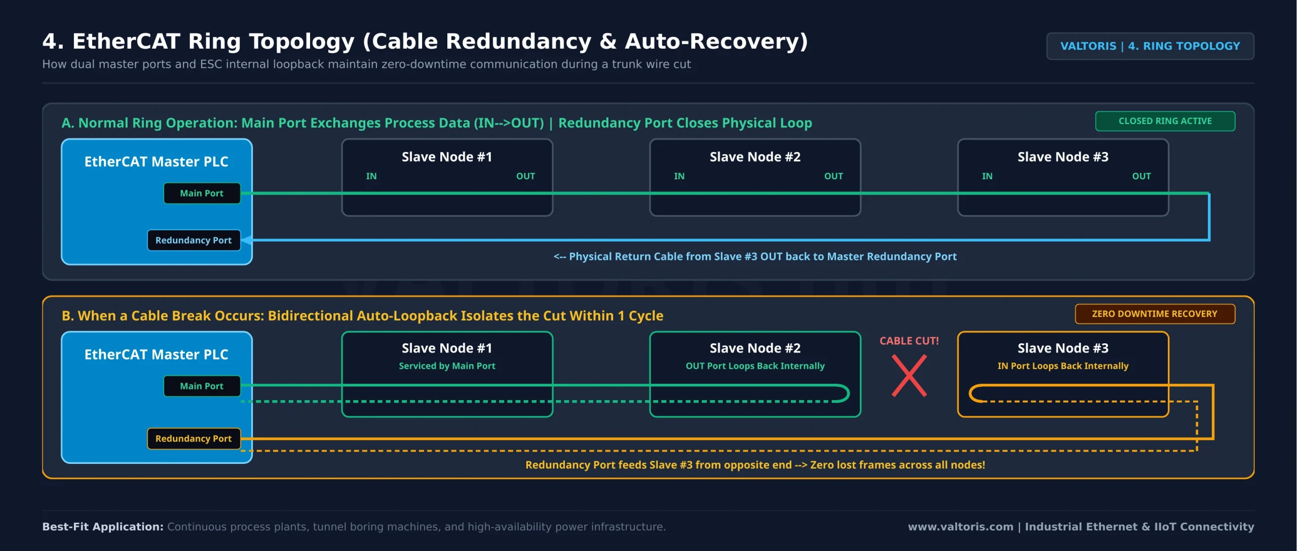
When absolute uptime is required, engineers extend a linear or tree layout into a Ring Topology by routing the final slave’s OUT port back to a second Ethernet interface (Redundancy Port) on the master PLC:
- Normal Ring Operation: The Main Port from the master transmits process frames downstream (
IN → OUT) to exchange data, and the Redundancy Port transmits frames upstream (OUT → IN) without changing process data. - During a Cable Break: If a cable break occurs between Slave #2 and Slave #3, the adjacent ESC chips immediately detect the link loss and automatically turn on internal auto-loopback on both ends of the cable break. The Main Port’s frame goes to Slaves #1–#2 and returns. The Redundancy Port’s frame comes from the other end and goes to the remaining slaves, achieving a zero-downtime switchover within a single cycle.
How EtherCAT Actually Moves Data (Physical Line vs. Logical Ring)
Looking at the four diagrams above, you might notice something strange: only the Ring topology physically wires the last device back to the PLC. In a Line, Star, or Tree layout, the final slave’s OUT port is left completely empty. So how does the data frame ever return to the master?
The answer is the core architectural rule that separates EtherCAT from standard office Ethernet—and the exact reason why standard IT switches fail on an EtherCAT bus: no matter how you wire your devices physically, EtherCAT always moves data inside a closed “Logical Ring.”
The secret is inside your standard Cat5e Ethernet cable. Unlike older serial buses that share a single wire pair and need termination resistors or an active RS485 hub for star vs. daisy-chain wiring, standard 100Mbps Ethernet is full-duplex—meaning each cable contains separate wire pairs for sending (TX) and returning (RX) data. According to the EtherCAT Technology Group (ETG) Functional Principle, a single data frame travels through your network in two steps:
- Processing “On-the-Fly”: As the Ethernet frame passes through a slave’s dedicated EtherCAT Slave Controller (ESC) chip, the slave reads its assigned output data and inserts its input data while the frame is moving at wire speed. This introduces only a few nanoseconds of hardware propagation delay.
- Automatic Loopback (Auto-Close): Every ESC chip continuously monitors the link status of its downstream port. When the last slave in a segment detects that nothing is plugged into its
OUTport, its internal hardware switch automatically loops the signal back onto the return RX pair toward the master.
Hence, irrespective of whether your physical layout is a straight line, a vertical drop-tree or an EtherCAT star topology, the underlying protocol is always a single closed Logical Ring. Thus the bulky TCP/IP stacks are avoided and usable process data represents more than 90% of each Ethernet frame.
Click the red button below to see what happens to downstream devices when Node #2 (S2) loses power or gets unplugged:
The #1 Mistake: Standard Ethernet Switch vs. Dedicated EtherCAT Switch (Junction)
After seeing the 1-In-5-Out branching in the simulator above, a common question comes up: “Can I just use a standard 5-port or 8-port unmanaged Ethernet switch to split my EtherCAT trunk?” On the outside, both devices have standard RJ45 ports and use Cat5e cables—making a cheap office or industrial TCP/IP switch the #1 commissioning mistake on the shop floor.
You cannot use a standard Ethernet switch inside a real-time EtherCAT segment for two hardware reasons: first, a standard switch uses store-and-forward memory queues (reading MAC tables before forwarding packets), which injects random queuing jitter that breaks Distributed Clocks (DC) servo synchronization. Second, standard switch chips cannot perform the nanosecond Port Auto-Close loopback shown above to keep the EtherCAT logical ring intact. Even though engineers often search for an “EtherCAT switch” or industrial EtherCAT hub, the device you actually need is a dedicated EtherCAT junction slave built on internal ESC silicon:
| Technical Parameter | Standard Ethernet Switch (Unmanaged / Managed) | Dedicated EtherCAT Switch / Junction |
|---|---|---|
| Internal Silicon | Standard IEEE 802.3 Store-and-Forward ASIC | Dedicated Cascaded EtherCAT Slave Controllers (ESC) |
| Frame Forwarding | Reads MAC table, buffers complete packet, queues & forwards | Processes frames on-the-fly in deterministic port order (IN 1 → Out 2..6) |
| Processing Latency | 10 µs to several milliseconds (variable queuing jitter) | Nanosecond-level hardware propagation delay (Zero jitter) |
| Distributed Clocks (DC) | Unsupported (destroys servo axis synchronization) | Full hardware Distributed Clocks (DC) timestamp compensation |
| Branch Disconnect Behavior | Drops port link; cannot close internal EtherCAT logical ring | Instant hardware Port Auto-Close isolates broken drop-lines |
Standard switches inspect destination MAC addresses and buffer packets in memory queues. Because an EtherCAT telegram is a broadcast/summation frame (EtherType 0x88A4) that must visit every slave sequentially and loop back to the master, a standard switch introduces random microsecond jitter that breaks Distributed Clocks (DC) synchronization. By contrast, a dedicated 6-port EtherCAT switch splitter (junction slave) contains internal ESC chips that route the frame strictly out Port 2, receive its loopback, route it out Port 3, and so on—preserving nanosecond determinism.
Engineering Tip: Where to Place Your Distributed Clocks (DC) Reference Clock in Star Topologies
The EtherCAT master automatically picks the first DC-capable slave after the PLC as the System Reference Clock (T0) and dynamically measures propagation delays on each branch (in strict depth-first order: IN 1 → Port 2 branch → return to Port 2 → exit Port 3). Never locate your Reference Clock at the end of a removable Hot Connect drop line. Use a hardware ESC junction that natively supports Distributed Clocks (DC) right at the trunk split. This guaranties that sub-microsecond timestamp propagation remains stable even when downstream branches disconnect.
The 4 Golden Rules of EtherCAT Wiring (Ports, Cables, Distance & Power)
Once you have chosen the right topology and replaced standard switches with dedicated ESC junctions, the next hurdle is inside the control cabinet. Because EtherCAT runs at 100Mbps on-the-fly without TCP/IP retries, a single reversed plug or unshielded patch cord will halt the bus. Follow these four wiring rules to avoid commissioning headaches:
Rule 1: Respect IN and OUT Ports (Why Auto MDI/MDI-X Won’t Save Reversed Plugs)
On a standard office switch, any cable can plug into any port. On an EtherCAT slave or junction, port assignment is strictly directional. You will often see datasheets state that ports support Auto MDI/MDI-X. Do not misunderstand this spec: Auto MDI/MDI-X only means the port automatically detects straight-through versus crossover TX/RX wire pairs—it does not allow you to swap the logical IN port with an OUT port.
Furthermore, different automation vendors label their ports inconsistently, leading to frequent miswiring on multi-vendor panels. Always consult the slave’s ESI file or hardware manual to verify the correct IN/OUT port assignments before wiring.
| Hardware Vendor / Device Type | Upstream Trunk Input (Port 0) | Downstream / Branch Outputs (Port 1..N) | Consequence of Reversing IN & OUT |
|---|---|---|---|
| Standalone 6-Port ESC Junction | IN 1 (Bottom-left RJ45) | 2, 3, 4, 5, 6 (5 Branch Outputs) | Topology tree scrambles; downstream slaves fail to enter Operational (OP) state. |
| Beckhoff / Standard ESC Chips | Port 0 (A) / ECAT IN / X1 | Port 1 (B), Port 2 (C), Port 3 (D) | Master reports topology mismatch against configured ENI file. |
| Omron / Yaskawa Servo Drives | ECAT IN / CN1A | ECAT OUT / CN1B | Immediate loop closure at wrong port; all subsequent drives disappear from scan. |
| Delta / Generic Remote I/O | PORT 1 or IN | PORT 2 or OUT | Intermittent initialization failure or unexpected alias addressing order. |
Rule 2: Use Shielded Cat5e/Cat6 Cables & High-Flex Drag-Chain Wire
Because 100BASE-TX EtherCAT only transmits on pins 1, 2, 3, and 6, cable selection is critical when routing near high-frequency variable frequency drives (VFDs) and servo motor cables. As documented in the ETG.1600 Official EtherCAT Installation Guideline, using unshielded office patch cords is a recipe for instant bus failure when meeting industrial EtherCAT cable specifications.
| Installation Parameter | ETG Official Specification | Field Engineering Reason |
|---|---|---|
| Shielding Grade | Cat5e SF/UTP or S/FTP (Braided + Foil shield) | Foil blocks high-frequency servo PWM switching noise; braid drains low-frequency magnetic induction to ground. |
| Conductor Count & Gauge | 4-Wire (Quad) AWG22 preferred over 8-Wire AWG24/26 for long/noisy runs | EtherCAT only uses 4 pins. In extreme EMI zones, the 4 unused floating wires in an 8-wire cable can induce unwanted capacitive crosstalk. AWG22 minimizes voltage attenuation up to 100m. |
| Static Cabinet vs. Drag Chain | Solid core for fixed trays; Stranded High-Flex PUR for robotics/gantries | Solid copper conductors work-harden and fracture inside moving drag chains within weeks, causing intermittent Lost Link faults. |
| RJ45 Connectors | 360° Metal-shielded RJ45 plugs | Plastic RJ45 plugs break the shield drain path right at the ESC port entry, acting as EMI antennas. |
Rule 3: The 100-Meter Distance Limit (Per Segment, Not Total Network!)
One common misconception with EtherCAT max cable length is that the whole network cannot be longer than 100 meters. In fact, the 100-meter limit is strictly for the point-to-point copper cable between any two active ESC nodes (using AWG22 shielded Cat5e or better).
Every EtherCAT slave and junction acts as a physical layer signal repeater that reshapes and regenerates the electrical waveform. By cascading standalone junctions or slave nodes every 100 meters, a single copper EtherCAT network can span several kilometers across a factory floor without fiber converters. However, hardware junctions cannot bend the laws of physics. If your layout requires a strict 150-meter unbroken gap between two factory buildings without mid-point power access, copper junctions won’t help—you must transition to EtherCAT Fiber Optic converters for that specific run.
Rule 4: Cabinet Grounding, Power & Enclosure Rating
Even double-shielded cables will drop frames if cabinet grounding and power wiring are overlooked:
- Drain Noise via
PG& Metal DIN Rail: Always connect the Protective Ground (PG) pin of the terminal block and mount metal-housed junctions on an unpainted 35mm DIN rail to bleed off high frequency VFD noise (IEC 61000-4-5 Level 3 surge protection). - Check Non-Standard Power Buses: AGVs are powered by 48V DC batteries, while most panels run on 24V AC. Older retrofits sometimes run on 24V AC. A non-polarized 9-60V DC / 24V AC input jack means you won’t need extra step-down converters and you won’t fry the board with reversed wires.
- Match IP40 vs. IP67 to the Location: Compact IP40 RJ45 junctions are perfect inside control cabinets or local junction boxes, exposed wet robotic arms need sealed IP67 M12 blocks.
Field Troubleshooting: Decoding WKC, Lost Links, and CRC Errors
Even if your cabinet is wired strictly by the four rules above, moving drag-chain cables eventually fatigue and RJ45 latches vibrate loose on the shop floor. The good news is that you never have to unplug cables one by one to find a bad wire. Because every ESC chip tracks hardware error counters on each individual port, you can pinpoint the exact faulty cable segment right from your PLC software when EtherCAT lost frames occur:
| Master Diagnostic Counter | Symptom on the Machine | Root Physical Cause | Exact Pinpoint & Fix Strategy |
|---|---|---|---|
| Working Counter (WKC) Drops to 0 | Sudden bus halt; multiple downstream axes fault simultaneously. | Each slave increments the frame’s WKC as it passes through. If a node loses power or unplugs, the frame never returns. | Move critical drop-lines off the main daisy-chain onto an ESC junction so Port Auto-Close isolates the dead station. |
| Lost Link Counter Increments (Port A/B) | Brief communication dropouts when a gantry moves or vibrates. | Physical electrical link dropped for milliseconds—classic sign of a loose RJ45 latch or broken solid-core wire inside a drag chain. | Check which slave shows Lost Link on Port 0 (IN). Replace the cable between that slave and its immediate upstream neighbor with high-flex stranded cable. |
| Rx Error / Frame CRC Error Spikes | Bus runs fine when idle, but errors climb rapidly as soon as servo drives enable. | Electromagnetic interference (EMI) corrupting bits in transit while physical link stays up. | Separate Ethernet cables from 400V motor leads by at least 20cm; replace plastic RJ45 connectors with 360° shielded metal plugs; verify cabinet PE bonding. |
| Invalid Frame / Forwarding Error | Downstream slaves show errors even though their own cables are brand new. | When Slave #3 corrupts a frame due to local EMI, it marks the frame invalid and forwards it downstream. | Golden Rule: Ignore downstream forwarding errors. Find the first upstream node where Rx CRC Error > 0—the bad cable is directly upstream of that specific port. |
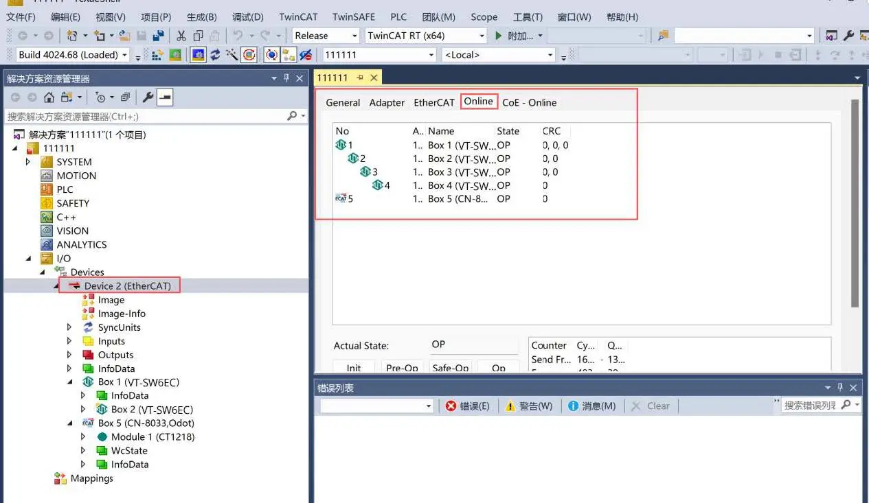
OP state with 0, 0, 0 CRC errors across all ports.Conclusion: Build for Maintenance, Not Just Day-One Commissioning
The advantage of a pure linear daisy-chain is in initial panel assembly where no infrastructure hardware is required. But machines don’t work in clean laboratories. A drag chain will flex millions of times over its five year life cycle. Operators will change tooling. Maintenance technicians will shut down individual safety zones.
Designing a resilient ethercat topology means removing single points of failure before the machine ships . Your main control loop is protected from localized cable faults and long term down time through strict Cat5e shielded wiring standards and dedicated hardware ESC junctions that divide your network into isolated star and tree branches.
Frequently Asked Questions (FAQ)
1. Can I use a Gigabit (1000BASE-T) switch or cable for my EtherCAT network?
2. Does an EtherCAT junction require an IP address or web interface configuration?
3. What happens if I accidentally plug the Master PLC into a downstream output port instead of IN?
IN port to properly traverse the internal ESC chips and initiate the auto-loopback sequence.