

When replacing industrial sensors, confusing a normally closed vs normally open contact introduces a direct logic inversion into your control system. The standard software fix is to change a PLC’s Examine If Open (XIO) instructions, but factory floor realities like OEM password locks, missing software licenses or strict Management of Change (MOC) protocols often make immediate code changes impossible.
This guide details three hardware and edge-level methods to convert normally closed to normally open physical logic locally, allowing production to resume without accessing the PLC source code.
The Bottleneck: Sensor Mismatches and Locked PLCs
Before diving into the hardware wiring diagrams below, here is a quick look at why a physical bypass is often the only immediate option on the factory floor.
When logic inversion occurs on the floor, waiting for the exact NC replacement part to make its way through supply chain delays is often not an option. But getting past that with a normally open (NO) sensor usually runs into a software roadblock. Often you are prohibited from connecting a laptop to the PLC either administratively or technically to toggle the digital input tag:

| The Roadblock | Why It Happens | Impact on Downtime |
|---|---|---|
| OEM Password Lock | Machine builders (OEMs) often lock their ladder logic blocks with passwords to protect intellectual property and prevent unauthorized tampering. | Cannot modify code until the OEM support desk opens (often in a different time zone). |
| Missing Software Licenses | Modern PLC software (e.g., TIA Portal, Studio 5000) requires expensive, node-locked licenses that the night-shift maintenance laptop might not have. | Forced to wait for the senior controls engineer to arrive on-site. |
| Management of Change (MOC) | In validated environments (e.g., FDA-regulated pharma, strictly adhering to 21 CFR Part 11), modifying a single line of PLC code requires a formal risk assessment, code review, and QA approval. | Modifying software can take days or weeks of paperwork. A hardware fix is required immediately. |
The Basics: Normally Closed vs Normally Open Sensors
(For veteran engineers, this is just a quick baseline check. Feel free to skip directly to Fix #1.)
Before we bypass the PLC, we must understand the electrical state of the sensor in its “normal” (unactuated) condition. Whether you are dealing with a standard proximity sensor or a safety-critical normally closed limit switch, “normal” refers to the sensor sitting on a shelf, not detecting a target.
| Sensor Type | Unactuated State (No Target) | Actuated State (Target Present) |
|---|---|---|
| Normally Open (NO) | Circuit is Broken (0V at PLC input) | Circuit is Closed (24V at PLC input) |
| Normally Closed (NC) | Circuit is Closed (24V at PLC input) | Circuit is Broken (0V at PLC input) |
Fix #0: The “Lucky Break” (Check for L.O./D.O. Switches)
Before rewiring anything, inspect the body of your replacement sensor. Many modern photoelectric sensors feature a small physical rotary switch labeled L.O. / D.O. (Light Operate / Dark Operate). Toggling this switch effectively inverts the logic internally. If your sensor has this, simply flip it, test the output, and you are done. If not, proceed to Fix #1.
Fix #1: The 4-Wire Sensor Swap (The Wiring Trick)
If you are lucky, the replacement sensor you pulled from the inventory is a 4-wire proximity or photoelectric sensor. Many modern 4-wire sensors are built with complementary outputs, meaning they possess both a NO and an NC output simultaneously.
Standard IEC industrial sensor wiring utilizes specific color codes. If your system is acting inverted, check the terminal block. You can likely fix the logic simply by swapping the signal wire.
| Wire Color | Function | Action for Logic Inversion |
|---|---|---|
| Brown | +24VDC (Power) | Leave connected to 24V supply. |
| Blue | 0V / Common | Leave connected to 0V / Ground. |
| Black | Normally Open (NO) Output | Disconnect this wire if the PLC expects NC logic. |
| White | Normally Closed (NC) Output | Connect this wire to the PLC input terminal instead of Black. |
Pro Tip: Cap and isolate the unused wire (Black or White) with electrical tape or a terminal block to prevent accidental short circuits against the frame of the machine.
Crucial Check: Before wiring, ensure that the Sinking/Sourcing (NPN/PNP) type of your sensor matches the PLC input card. Switching NO/NC wires will not fix a PNP vs NPN mismatch.
💡 Tip: Feel free to share or use this schematic in your own documentation or forum posts (just link back to us!).
Fix #2: The “Ice Cube” Relay Trick (The Hardware Inversion)
What if your replacement sensor only has 3 wires (Brown, Blue, Black)? It is strictly a single-output device. If you cannot change the PLC code, you must physically invert the electrical signal before it reaches the PLC input card.
Electricians have used the “Ice Cube Relay” trick for decades. By using the sensor output to energize a small 24VDC SPDT (Single Pole Double Throw) interposing relay, you can wire the PLC input through the normally closed relay contacts.
- When the sensor is OFF (0V): The relay coil is de-energized. The NC contact is closed. The PLC receives 24V.
- When the sensor is ON (24V): The relay coil energizes. The NC contact opens. The PLC receives 0V.
💡 Tip: Feel free to share or use this schematic in your own documentation or forum posts (just link back to us!).
This hardware trick is effective but has some major drawbacks . A mechanical relay in between takes up precious DIN-rail space and adds another mechanical failure point. Most importantly, mechanical relays introduce 10ms to 20ms of contact bounce and actuation delay. If this sensor is used for high speed counting or exact positioning the mechanical delay will cause the PLC to miss pulses or position the machine incorrectly.
Fix #3: Smart Edge I/O with Software Inversion (The Modern Approach)
Fix 1 and 2 will get your machine running tonight. But if you are designing a new control panel, planning a retrofit, or dealing with locked FDA-validated PLCs, relying on physical “Ice Cube” relays introduces a hidden problem: contact bounce and 10-20ms of mechanical actuation delay. If your sensor is used for high-speed counting or precise positioning, this mechanical latency will cause the PLC to miss pulses or position the machine inaccurately.
The modern engineering approach is to use smart Remote I/O modules to handle the inversion at the edge of the network. Instead of relying on a physical spring-and-coil relay, the I/O module intercepts the raw sensor signal, digitally flips the bit in its firmware (eliminating mechanical bounce), and outputs the corrected state to the legacy PLC via a clean dry contact.
Most industrial Modbus TCP controllers handle this via a built-in parameter often called DI-to-DO mapping or Edge-Level Logic Correction. Here is an example of what this software-based inversion looks like in a typical configuration utility:
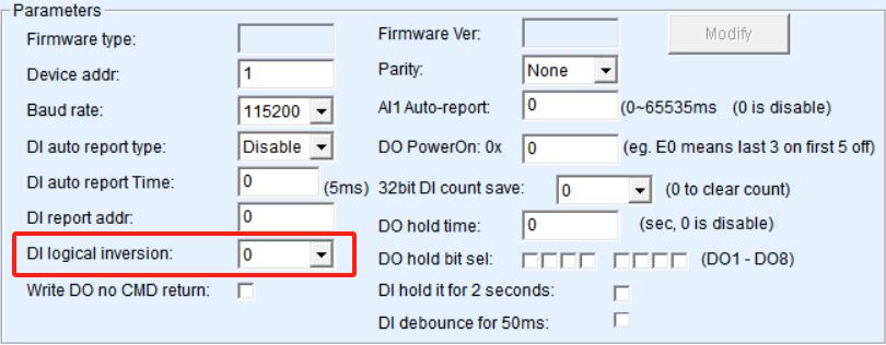
Instead of fighting locked PLC software, you can utilize a feature called Local DI-to-DO Mapping (or “DI Controls DO”). By connecting the new sensor to the smart I/O module, a technician simply uses the VirCOM utility to enable the DI Logical Inversion parameter, and then activates the DI Controls DO function (Register 72).
| Inversion Method | Physical Delay | Wiring Effort | Best For |
|---|---|---|---|
| Mechanical Relay | 10ms – 20ms (Bounce) | High (Requires adding hardware) | Legacy systems with no smart I/O. |
| PLC Code Modification | None (Scan time only) | None | Environments with unlocked, accessible source code. |
| Edge I/O Logical Inversion | ~10ms (Firmware debounce) | None | Locked PLCs, SCADA updates, validated systems. |
The hardware automatically translates the physical input (0V) into a logical 1 and fires its own local DO relay (e.g., DO1). Because this smart controller uses dry contact relays, you must supply the appropriate voltage to the DO terminal to match your PLC’s input requirement (Sinking or Sourcing).
💡 The “Water Valve” Analogy for Dry Contacts
Think of a dry contact relay as a physical valve on an empty pipe—it controls the flow, but it doesn’t supply the water (voltage) itself. The legacy PLC is the cup waiting for the water. Because different PLCs expect different “temperatures” (Sinking PLCs want +24V, Sourcing PLCs want 0V), you must pipe the correct voltage into the module’s DO1_COM terminal so it has the right signal to pass along when the valve opens.
- For a Sinking PLC Input (Expects 24V): Connect +24V to the module’s
DO1_COM. ConnectDO1_NOto the PLC’s Digital Input terminal. - For a Sourcing PLC Input (Expects 0V): Connect 0V (GND) to the module’s
DO1_COM. ConnectDO1_NOto the PLC’s Digital Input terminal.
💡 Tip: Feel free to share or use this schematic in your own documentation or forum posts (just link back to us!).
The PLC remains completely unaware that the sensor was swapped.
But here is the ultimate advantage over a standard mechanical relay: While the edge gateway handles the physical bypass for the legacy PLC, it simultaneously acts as an IIoT Gateway. It actively pushes the corrected data via Modbus TCP or MQTT to your SCADA/Cloud. You just upgraded a legacy machine to the cloud without touching a single line of validated PLC code.
Best Practice: Handling VFD Noise on the Factory Floor
When replacing mechanical relays with edge I/O modules, electrical noise from VFDs or heavy machinery is a common concern. Instead of just passing the raw signal, you can configure the edge controller to filter the data before it reaches the legacy PLC.
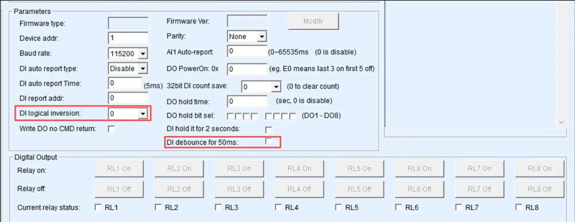
- Step 1: Enable Logic Inversion: Activate the
DI logical inversionparameter to flip the 0V input to a logical “1” internally. - Step 2: Apply Digital Debounce: To eliminate contact bounce and false-triggering from cable noise, set the hardware
DI debounceparameter (e.g., 50ms). The module will now ignore transient noise spikes and only pass a clean, reliable inverted signal to the PLC.
Engineering Reality Check: Limitations of Edge Inversion
While edge-level inversion solves immediate SCADA logic mismatches, engineers must account for two hardware realities when using the 8CH-IO series:
- Status LED Desynchronization: The physical DI indicator LEDs on the module will always display the raw electrical state. When logical inversion is enabled, the internal logic is flipped, but the physical LED is not. Document this for maintenance personnel to avoid confusion during visual panel inspections.
- Relay Output Latency: Since the module’s “DI controls DO” feature uses physical relay outputs (5A@AC250V/DC30V) to feed the legacy PLC, it introduces the same mechanical actuation delay (~10ms) as an ice-cube relay. This is perfectly fine for process control, level sensors, and general interlocking, but unsuitable for ultra-high-speed motion control (e.g., flying-shear encoders).
Safety Warning: When NEVER to Invert a Signal (Fail-Safe Logic)
While the three methods above efficiently resolve logic mismatches for standard operational sensors, applying these physical or software-based inversion shortcuts to safety-critical circuits is strictly prohibited.
Critical Life Safety Protocol
The techniques listed above are strictly for operational sensors (photoeyes, proximity switches, level sensors). You must never use software inversion or interposing relays to invert a safety-critical signal.
Emergency Stop (E-Stop) buttons, safety light curtains, and machine guard interlocks are intentionally wired as Normally Closed (NC) in series. This creates a Wire-Break Fail-Safe. According to global machinery safety standards (such as NFPA 79 and OSHA guidelines), a safety circuit must default to a safe state (machine stop) if power is lost or a cable is severed.
| Scenario | True NC Wiring (Correct) | Inverted NO Wiring (Dangerous) |
|---|---|---|
| Normal Operation | PLC sees 24V (Healthy) | PLC sees 24V (Software inverted) |
| Forklift cuts the sensor cable | PLC sees 0V -> Machine STOPS | PLC sees 0V -> Software inverts to 24V -> Machine KEEPS RUNNING |
If you use an edge controller to digitally invert an NO E-stop to look like an NC signal, a severed cable will register as a “0V” physical input, which the software will invert to a “1” (Healthy). The PLC will continue running the machine despite a disconnected E-stop. For safety circuits, you must purchase the correct NC hardware.
Future-Proof Your Next Machine Retrofit
A simple wire swap or a cheap ice-cube relay might get your machine running tonight. But when you are planning your next control panel retrofit or legacy machine upgrade, relying on mechanical workarounds limits your plant’s future.
Use Smart Edge I/O to digitize legacy sensors. You can bypass locked PLC code, execute local logic control, and stream BOM-optimized Modbus TCP/MQTT data directly to your SCADA or Cloud—all from a single DIN-rail device.
Planning an IIoT upgrade for your facility? Talk to our engineers about optimizing your BOM.
Frequently Asked Questions
How can I tell if an unmarked sensor is Normally Open or Normally Closed?
You can check the logic with a digital multimeter. 24VDC power to the sensor, but no target in front of it. Measure voltage between Output wire (Black or White) and 0V Common (Blue). If it reads 24V at rest it is Normally Closed (NC). If it reads 0V then it is Normally Open (NO).
Can I wire a Normally Closed sensor in series with a Normally Open sensor?
Wiring NO and NC sensors in series creates a logical AND gate where one condition must be true while the other is false to complete the circuit. While electrically possible, it is highly discouraged in industrial automation as it makes troubleshooting exceedingly difficult. It is better to wire them to separate digital inputs on your I/O module and handle the logic in the controller.
Does reversing the polarity on a 2-wire sensor change it from NO to NC?
No. Reversing the positive and negative wires on a DC proximity sensor will not invert its logic. In most cases, it will either trigger the sensor’s reverse polarity protection (preventing it from working) or instantly destroy the internal circuitry. Logic inversion must be handled via a 4-wire swap, a relay, or software configuration.
Why does my Normally Open sensor LED turn on, but the PLC input stays at 0?
If the sensor is firing but the PLC does not recognize the input, you likely have a Sinking vs. Sourcing mismatch. For example, if you connect a PNP (Sourcing) sensor to legacy plc input output modules wired for NPN (Sinking) signals, the current cannot flow correctly. See our complete guide on Sinking vs Sourcing I/O for wiring diagrams.
Can electrical noise from a VFD cause a Normally Open contact to false-trigger?
Yes. Electromagnetic Interference (EMI) from Variable Frequency Drives (VFDs) can induce voltages onto unshielded sensor cables. If the induced voltage exceeds the PLC’s input threshold (typically around 15V for a 24V system), the PLC will register a false “ON” signal. Applying hardware debounce on the I/O module can filter these microsecond spikes, and ensure you are using properly grounded shielded cables.
What if my sensor is Analog (4-20mA or 0-10V) instead of Digital?
This guide strictly covers discrete (digital) logic. You cannot invert a 4-20mA signal using a relay or wire swap. To invert an analog signal, you must scale it in the PLC or use an active signal conditioner. If you are experiencing signal bounce rather than inversion, check out our 4-20mA Troubleshooting Guide.
Can I invert the logic inside a Variable Frequency Drive (VFD)?
Yes. If your sensor lands on a VFD’s digital input block rather than the main PLC, almost all modern VFDs (like PowerFlex, Sinamics, or ACS880) allow you to invert terminal logic via their parameter menus. Look for parameters typically named “DI Logic,” “Active High/Low,” or “Terminal Inversion” in your VFD manual.