
How to Fix a Fluctuating 4-20mA Signal: A Complete Troubleshooting Guide
Is your PLC analog input bouncing frantically between 12mA and 15mA? Before you rush to replace the field sensor, stop. A fluctuating 4-20mA signal is rarely a hardware failure—it is almost always an electrical interference issue. Follow this systematic guide to diagnose and eliminate the noise.
- Ground Loops: Steady offsets or low-frequency oscillation. Requires galvanic isolation.
- EMI/VFD Noise: High-frequency jitter correlating with motor operation.
- Power/Wiring: Unregulated 24VDC ripple or improper shield grounding.
Fig 1: HMI visualization of severe electrical noise on a 4-20mA loop.
What Causes a 4-20mA Signal to Bounce or Fluctuate?
To fix the issue, you must first identify the underlying electrical mechanism causing the distortion.
1. Ground Loops (The Most Common Culprit)
A ground loop occurs when a 4-wire active transmitter and the PLC analog input card are tied to different earth grounds. The voltage potential difference between these two points drives an unintended “dark current” through your 4-20mA signal wire, completely skewing the ADC reading.
| Sensor Type | Ground Loop Risk | Why? |
|---|---|---|
| 2-Wire (Loop-powered) | Very Low | Both device and PLC share the same 24VDC supply. |
| 4-Wire (Self-powered) | Extremely High | The sensor has its own AC/DC ground, conflicting with the PLC panel ground. |
2. EMI/RFI and VFD Noise
Electromagnetic Interference (EMI) or Radio Frequency Interference (RFI) is induced when long, unshielded analog cables run parallel to high-voltage AC lines or Variable Frequency Drive (VFD) motor cables. The analog wire acts as an antenna, picking up high-frequency harmonics.
3. Physical Process Variations vs. Electrical Noise
Sometimes the noise is real. For example, a radar level sensor might detect physical water ripples inside a tank, causing the 4-20mA output to fluctuate legitimately. You must verify if the process itself is unstable before blaming the electronics.
4. Poor Wiring & Unregulated Power Supply
Loose terminal connections act as variable resistors. Additionally, if the 24VDC loop power supply is shared with heavy inductive loads (like solenoids), voltage drops and ripple will reflect directly into your analog readings.
3-Step Diagnostic Procedure (Isolate the Problem)
Do not guess. Use this three-step methodology to isolate the source of the noise.
Step 1: Disconnect and Use a Dummy Signal
Disconnect the field sensor wires from the PLC input card. Connect a standard 4-20mA signal generator (loop calibrator) directly to the PLC terminals and inject a steady 12.00 mA.
- If it stops jumping: The PLC card is fine. The issue is in the field wiring or the sensor.
- If it still jumps: The PLC analog card is faulty, or the panel’s 24VDC power is corrupt.
Step 2: How to measure 4-20mA with multimeter
To verify the actual loop current in the field, set your Digital Multimeter (DMM) to the milliamp (mA) scale. Disconnect the circuit and place the multimeter in series with the signal wire. If you cannot break the loop (to stop the process), then use a specialized milliamp process clamp meter (such as those recommended in Fluke’s guide on measuring 4-20mA loop signals) to measure the magnetic field directly over the wire.
Step 3: Check Shielding and Drain Wires
This is where the biggest arguments happen on the factory floor. Many electricians mistakenly apply VFD motor cable rules (which require double-ended grounding for Faraday shielding) to low-voltage analog cables.
According to standard instrumentation guidelines (see Industrial Ground Loop Principles), the foil/braid shield of an analog cable must be grounded at one end only (strictly at the PLC chassis ground). Grounding an analog shield at both ends turns your cable into a ground-loop conductor.
Hardware Solutions to Stabilize Erratic 4-20mA Loops
Once you have diagnosed the root cause, implement these physical solutions to permanently eliminate the noise.
Install a 4-20mA Signal Isolator (Galvanic Isolation)
If you have diagnosed a ground loop, the only real physical cure is to install a 4-20mA signal isolator. These devices use optical or magnetic transformers that provide galvanic isolation and decouple the field ground completely from the PLC ground. The modern way is to buy a small io controller with integrated digital and analog i/o and built in isolation that blocks common mode voltage very well , rather than separate expensive isolators.
Fig 2: Breaking ground loops using Galvanic Isolation topology.
Upgrade to Shielded Twisted Pair (STP) Cables
Ensure all analog runs utilize STP cables. The twisting of the wires ensures that any EMI induced into the cable affects both wires equally (Common Mode Noise), which modern PLC differential inputs can easily reject.
Ensure Dedicated and Regulated Loop Power (24VDC)
Isolate your analog power. Never power a 4-20mA loop from the same 24VDC power supply that drives contactors or solenoid valves.
The Ultimate Bypass: Digitize at the Edge
What if your analog cable is 100 meters long, buried in concrete, and runs right next to a noisy 500kW VFD motor? Traditional DIN-rail isolators inside the control panel cannot fix noise picked up along the long cable run.
In these extreme EMI environments, the modern industrial standard is to stop transmitting vulnerable analog signals over long distances. By deploying an io controller or a rugged Remote Terminal Unit directly next to the sensor (within 1 meter), you can digitize the signal at the source and transmit it safely via Ethernet.
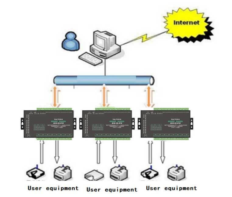

Fig 3: Bypassing long analog runs by digitizing locally to Modbus TCP (Source: Valtoris Hardware Manual)
Upgrade to a Noise-Proof Architecture
- 100m+ copper analog wire.
- Highly susceptible to VFD EMI noise and capacitive coupling.
- Built-in Isolation: System-level bus isolation natively breaks field ground loops.
- Absolute EMI Immunity: Digital packets are entirely immune to factory floor noise.
Software Fixes: Filtering Noise at the PLC / Controller
If you are waiting for hardware components to arrive, or if the noise is a minor +/- 0.1mA jitter, you can implement software compensation as a temporary patch.
Implement a Moving Average Filter
Increase the sampling window in your PLC logic. Instead of acting on a raw 30ms sample, write a routine that stores the last 10 samples, calculates the average and outputs the smoothed value. Warning: This adds phase delay and should not be used on fast PID control loops.
// Simple First-Order Low-Pass filter to dampen jitter
"DB_Analog".Filtered_Value := "DB_Analog".Filtered_Value +
    0.1 * ("Raw_Analog_Input" - "DB_Analog".Filtered_Value);
Adjusting Analog Input Card Resolution & Deadband
Implement a deadband in your SCADA or PLC logic to ignore micro-fluctuations. If the process needs 0.5 PSI accuracy then the logic should be set to ignore any changes less than 0.2 PSI to avoid false alarms.