

A serial to Ethernet converter sits between your PLC, flow meter, or sensor and your network. On one side, it connects to the device’s RS232 or RS485 port. On the other, it plugs into an Ethernet switch. The goal is simple: get data from the serial device onto the network so it can be accessed from a computer.
The execution is not that simple. It takes a steps to get it right. First the wiring needs to be correct. Then the network settings need to match the system. The serial parameters are also very important. They need to be exactly right. This guide will walk you through each step of the execution process, with real world examples. It will also help you with troubleshooting when the execution does not work the time. The guide has examples to help you understand the execution process better.
Before You Start: What the Market Says
The global market for serial to Ethernet converters was valued at $799.2 million in 2024 and is projected to reach $1.5 billion by 2035, growing at 5.9% annually . Another research firm puts the 2024 market at $420 million, forecasting $710 million by 2033 .
Why is this market growing? Because 30–40% of industrial equipment still uses serial communication (RS‑232, RS‑485, RS‑422) . Factories, water plants, and energy facilities need to connect these legacy devices to modern networks. This guide is for the people doing that work—technicians, engineers, and system integrators who need a clear, step‑by‑step process to get data flowing.
What You’ll Need
- Your serial to Ethernet converter
- Power supply (9-24V DC, most industrial panels have 24V)
- Ethernet cable
- Serial cable appropriate for your device (RS232, RS485, or RS422)
- A computer on the same network
- Device manual for your serial equipment (for baud rate, parity, etc.)
Step 1: Wiring – Get This Right or Nothing Works
The most common problem is incorrect wiring. Take your time here.
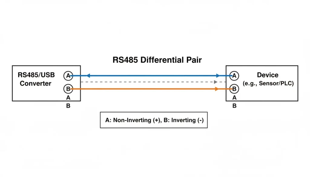
RS485 Wiring
RRS485 uses two wires, usually labeled A and B (or Data+ and Data-). According to the TIA/EIA-485 standard , RS485 supports up to 1,200 meters and up to 32 devices per segment.
| Converter | Your Device |
|---|---|
| A (or Data+) | A (or Data+) |
| B (or Data-) | B (or Data-) |
| GND (optional) | GND |
Important: Some manufacturers swap the labels. If you get no data, try swapping A and B. It won’t damage anything.
For longer runs (over 100 meters), use shielded twisted pair cable and connect the shield to ground at one end only.
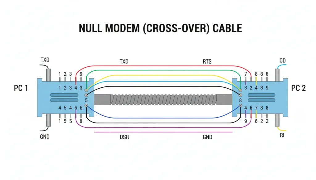
RS232 Wiring
RS232 needs three wires: TX, RX, and GND. The tricky part: TX on one side goes to RX on the other.
| Converter | Your Device |
|---|---|
| TX | RX |
| RX | TX |
| GND | GND |
RS232 is point-to-point only. Max distance about 15 meters.
RS422 Wiring
RS422 uses four wires for full duplex: TX+, TX-, RX+, RX-.
| Converter | Your Device |
|---|---|
| TX+ | RX+ |
| TX- | RX- |
| RX+ | TX+ |
| RX- | TX- |
Less common than RS485. Used when you need simultaneous send and receive.
Step 2: Power and Network Connection
Most industrial converters use 9-24V DC. If you’re in a control panel, you likely have 24V available. Wire it to the terminal block.
Plug an Ethernet cable into the converter and connect it to your switch or directly to your computer.
The power LED should light up. The network LED may blink or stay solid depending on link status.
Step 3: Find the Converter on Your Network
New converters either have a default IP address or use DHCP to get one from your router.
Method 1: Default IP
Check the manual. Common defaults are 192.168.1.254, 192.168.0.7, or 192.168.2.1. Set your computer to a matching IP (e.g., 192.168.1.100) and try to ping the converter.
Method 2: Discovery Tool
Most manufacturers provide a Windows utility that finds converters on the network. Valtoris provides VirCom. Run it, click “Search”, and it lists all converters it finds along with their IP addresses.
Method 3: Check Router DHCP List
If your converter uses DHCP, log into your router and look at the connected devices list. Find one that matches the converter’s MAC address (on a sticker on the device).
Once you have the IP, open a browser and enter it. You should see the converter’s configuration page.

If you can’t get to the page:
- Check your computer’s IP is in the same subnet
- Disable your firewall temporarily
- Try a different browser
Step 4: Configure Network Settings
Once you’re in the configuration page, go to network settings.
| Setting | Recommendation | Why |
|---|---|---|
| IP address | Static | DHCP can change, breaking your connection |
| Subnet mask | 255.255.255.0 | Standard for small networks |
| Gateway | Router IP | Needed if accessing from other subnets |
| DNS | Optional | Only needed if using domain names |
Write down the IP you assign. You’ll need it later.
Step 5: Configure Serial Port Settings
This is the most critical step. Every setting here must match your connected device exactly.
| Parameter | Your Device Value | Common Values |
|---|---|---|
| Baud rate | __________ | 9600, 19200, 38400, 115200 |
| Data bits | __________ | Usually 8 |
| Parity | __________ | None, Even, Odd |
| Stop bits | __________ | Usually 1 |
| Flow control | __________ | None, RTS/CTS, XON/XOFF |
Where to find these values:
- Check your device’s manual
- Look at existing configuration if it’s already working
- Defaults are often 9600, 8, N, 1 for Modbus RTU devices
If these don’t match, you’ll get no data or garbage data. No exceptions.
Step 6: Choose the Right Operating Mode
This is where “control” happens. The mode determines how data flows.
| Mode | Who Initiates | Connection Type | Best For |
|---|---|---|---|
| TCP Server | Computer connects to converter | Persistent | One computer polling one device |
| TCP Client | Converter connects to computer | Persistent | Converter pushing data to fixed IP |
| UDP | No connection | Connectionless | Broadcast, multiple receivers |
TCP Server (Most Common)
Set the converter as TCP Server on a specific port (default often 502 for Modbus, or 4001-4008 for general use).
Your computer acts as TCP Client. It connects to the converter’s IP and port. Once connected, data flows both ways.
Example: SCADA system polling a PLC every second. SCADA initiates the connection, sends requests, gets responses.
TCP Client
Set the converter as TCP Client, and give it the IP address and port of your computer.
The converter initiates the connection. If the connection drops, it tries to reconnect.
Example: Remote weather station that pushes data every 15 minutes. The converter knows where to send it.
UDP
No connection setup. The converter sends data packets to an IP and port, whether anyone is listening or not. Can also broadcast to multiple addresses.
Example: Status updates that multiple displays need to see. If a packet is lost, the next update will come soon enough.
Step 7: Software Side – How Your Computer Talks to It
You have three options depending on your application.
Option A: Socket Programming
If you’re writing your own software, open a TCP socket to the converter’s IP and port. Send your data, read responses.
Works with any language that supports sockets (Python, C#, Java, etc.).
Python example (very simplified):
import socket
s = socket.socket(socket.AF_INET, socket.SOCK_STREAM)
s.connect((‘192.168.1.100’, 4001))
s.send(b’\x01\x03\x00\x00\x00\x01′)
response = s.recv(100)
print(response)
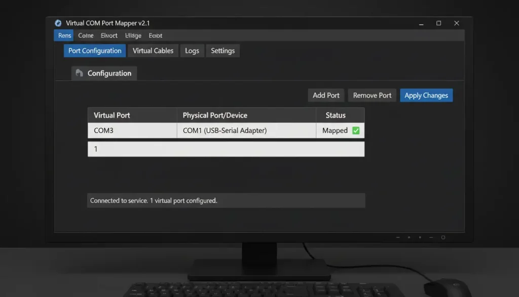
Option B: Virtual COM Port
This is the easiest path if you have existing software that expects a physical COM port.
Install virtual COM software (Valtoris provides VirCom). It creates virtual COM ports on your system. Map one of them to the converter’s IP and port.
Your software sees COM5 (or whatever you chose) and talks to it normally. The software redirects everything to the network.
Pros: No software changes needed.
Cons: Requires driver installation, slight overhead.
Option C: Modbus TCP
If your device uses Modbus RTU, many converters can act as Modbus gateways. Your SCADA system talks Modbus TCP to the converter’s IP. The converter translates to Modbus RTU and sends to the device.
No virtual COM ports needed. Just point your SCADA to the IP address.
Step 8: Test the Connection
Before calling it done, verify data is flowing.
Simple test:
- Open a TCP test utility (like Hercules, Termite, or PuTTY in raw mode)
- Connect to the converter’s IP and port
- Send a few bytes your device should respond to (e.g., a Modbus query)
- Watch for a response
If you get nothing:
| Symptom | Likely Cause | Try This |
|---|---|---|
| Can’t ping converter | IP conflict or wrong subnet | Check both IPs, adjust one |
| Ping works, no connection | Firewall | Disable firewall temporarily |
| Connect but no data | Wiring wrong | Swap A/B or TX/RX |
| Connect but garbage | Baud rate wrong | Verify device settings |
| Data intermittent | Ground loop or interference | Use shielded cable, check grounding |
Step 9: Make It Permanent
Once everything works, lock it down:
- Save the configuration – Most converters have a “save” button. Use it.
- Document everything – Write down the IP, port settings, and serial parameters. Tape it inside the panel if possible.
- Secure it – Change the default admin password.
- Test power loss – Pull the plug, plug it back in. Does it reconnect automatically? (It should.)
Real Example: Putting It Together
Scenario: You have a Modbus RTU flow meter at 9600 baud, 8, N, 1. You want to read it from a PC running Modbus poll software.
Hardware: 1CH-RS232/485/422-ETH
Steps:
- Wire RS485 A/B to meter A/B. Connect 24V power.
- Plug Ethernet into same network as PC.
- Find converter IP (used discovery tool, found 192.168.1.105).
- Open browser, go to 192.168.1.105.
- Set network to static IP (keep 192.168.1.105).
- Set serial port: 9600, 8, N, 1.
- Set operating mode: TCP Server, port 502 (Modbus standard).
- Save.
- On PC, open Modbus poll. Set connection to TCP, IP 192.168.1.105, port 502.
- Poll register 1. Get data.
Result: Total time: 20 minutes. The facility avoided trenching new cable, saving an estimated $8,000 in installation costs.
Industrial Considerations: What to Look For
If the installation is in a real industrial environment (not an office), these specs matter:
| Feature | What to Look For | Why |
|---|---|---|
| Temperature range | –40°C to 85°C | Control panels get hot in summer, cold in winter. |
| Mounting | DIN rail | Standard in industrial panels; keeps wiring organized. |
| Power | 9–24V DC | 24V is everywhere in industrial; avoid 5V USB‑powered converters. |
| Isolation | 1500V or 3000V | Prevents ground loops and protects equipment on long runs. |
| Enclosure | Metal | Helps with heat dissipation and EMI shielding. |
According to industry data converters with these features last more than 100,000 hours on average before they fail. This is compared to than 50,000 hours for regular consumer devices. Yes they cost more at first. They are very reliable, in the long run, which makes them worth it.
Pre‑Deployment Checklist
Before starting the installation, run through this:
- Wiring confirmed — Polarity correct? Shield grounded at one end?
- Serial settings — Baud rate, parity, data bits, stop bits match device manual.
- Network settings — Static IP assigned, not conflicting with other devices.
- Operating mode — TCP Server or Client? Port number correct?
- Software path — Socket, virtual COM, or Modbus TCP? Tested with a simple tool.