

RS485 repeaters do one thing: they take a RS485 signal in and send a clean copy of the RS485 signal out. They work well when the RS485 repeaters are wired correctly.
According to maintenance logs from industrial sites, over 80% of repeater-related problems come from installation errors, not defective hardware . The RS485 standard specifies a maximum single‑segment distance of 1200 meters (4000 feet) and up to 32 unit loads per segment . Repeaters allow you to exceed these limits, but only if you follow basic wiring rules.
Here are ten mistakes that people have written about in field reports and technical standards. And the fixes, for these mistakes really do work. These mistakes are things that people have actually done wrong. The fixes are things that will help you get it right.
Mistake 1: Placing the Repeater at the Physical End of the Bus
The problem: The repeater is installed after the termination resistor at the far end, treating it like any other node. By the time the signal reaches it, it’s already weak and possibly distorted.
The solution: Install the repeater where the signal starts to get weaker. This is usually 800 to 1000 meters or after 20 to 25 devices. The repeater splits the bus into two parts that work on their own. Each part has a termination, at its far ends. The repeater sits in the middle of the network.
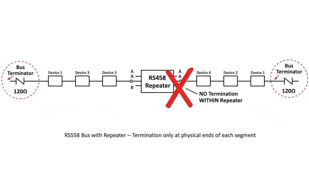
Caption: You should put the repeater in the middle not at the end. When you add a segment it needs to have its own termination at the far end of that segment. The repeater is important so it should be placed in the middle. Each new segment of the line gets its termination and that termination is at the far end of the new segment. The repeater in the middle helps, with this.
Mistake 2: Swapping the A and B Wires
The problem: Manufacturers label the two signal wires inconsistently. One vendor’s A may be the non‑inverting line; another’s A may be inverting. Connecting A to A and B to B without checking can result in no communication at all.
The solution: If the network does not work after you turn on the power try switching the two wires at one end. This will not hurt anything. If the network starts working then you have fixed the problem with the wires being the way around. Make sure to write down the colors of the wires so you can do it correctly time you install the network.
Field data shows A/B polarity errors account for roughly 15% of first‑time installation failures .
Mistake 3: Enabling Termination on the Repeater
The problem: Some repeaters have built‑in termination resistors that can be switched on. Enabling them creates an impedance mismatch because the repeater is not at the physical end of the cable.
The solution: Disable any internal termination on the repeater. Termination resistors belong only at the two far ends of each segment . For high baud rates (above 115 kbps) or long cable runs, proper termination is essential —but only at the ends.
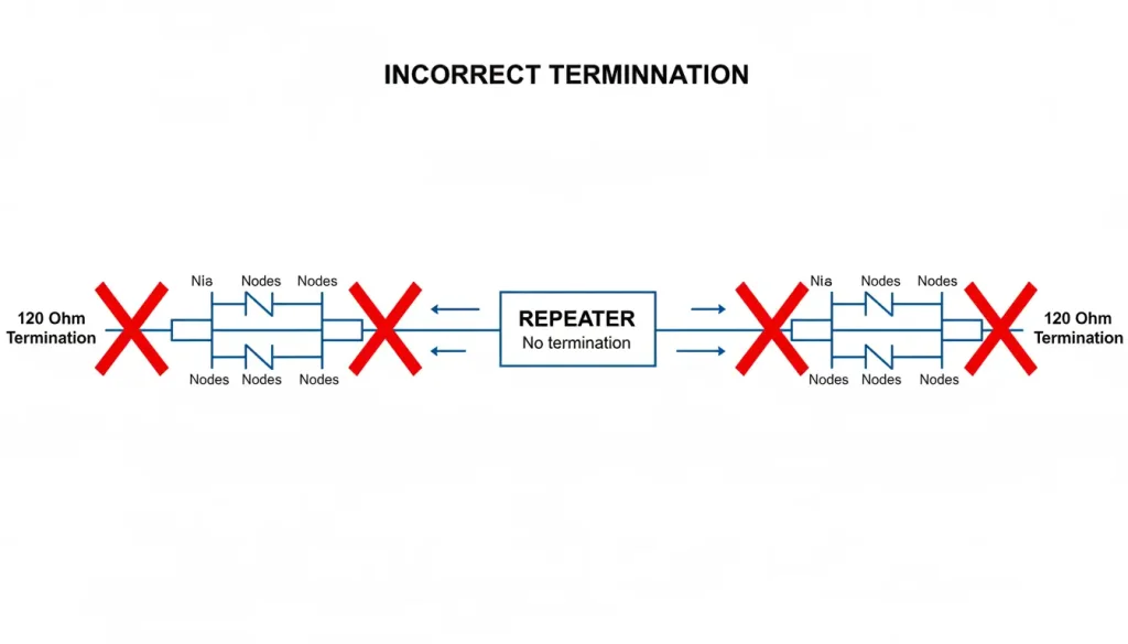
Caption: Terminate each segment at its ends, never at the repeater.
Mistake 4: Using an Undersized Power Supply
The problem: If you use a 5V USB adapter that’s not very good it may not be able to give the repeater the power it needs. The voltage, from the adapter may not be stable. This can cause the repeater to work sometimes and not work times. The repeater may also have trouble when it has to deal with a lot of data at the time. The 5V USB adapter may not be able to handle it.
The solution: Industrial RS485 repeaters typically need 9‑24V DC and can draw several hundred milliamps . Use a regulated supply within the specified range. In control panels, tap into the existing 24V DC bus. For outdoor sites, choose a supply rated for the expected temperature extremes.
The Analog Devices ADM2587E, a common isolated transceiver, operates at 5V but includes an integrated isolated DC‑DC converter . The actual power requirement depends on the full circuit.
The ADM2587E, from Analog Devices is an used isolated transceiver. It works at 5 volts. Has a built-in isolated DC-DC converter. The power it needs depends on the circuit it’s part of.
Mistake 5: Grounding the Shield at Both Ends
The problem: Connecting the cable shield to ground at each device can cause a problem. When you do this current starts flowing through the shield. This makes noise in the signal wires. As a result you get data errors. The shield and signal wires are close so noise, from the shield affects the signal. This can make your data unreliable.
The solution: When you are working with the shield you should connect it to the ground at one end. It is better to do this at the master side or, at the repeater. The other end of the shield should be left alone. Not connected to anything. However if the local rules say you have to do something with it you can tie the end of the shield to the ground using a small capacitor. This way you are following the rules and the shield is still working the way it should with the master side or the repeater and the small capacitor.
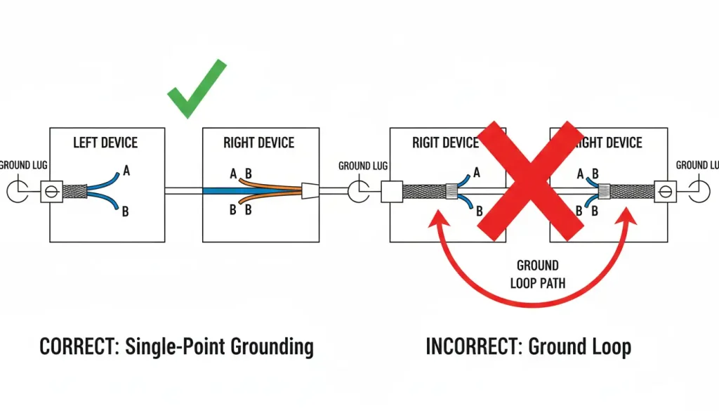
Caption: Shield at one end only to avoid ground loops.
Mistake 6: Long Stubs on Repeater Ports
The problem: Running a long cable from the repeater to a device creates a stub (branch). Long stubs cause signal reflections that corrupt data.
The solution: Keep stubs short. They should be under 3 meters. For high-speed networks keep them under 30 cm. Place the repeater close, to the devices it connects to. If devices are spread out use a hub with ports or multiple repeaters.
Mistake 7: Cascading More Than Four Repeaters
The problem: Chaining five or more repeaters to cover kilometers adds a delay. This delay is usually 1 to 3 milliseconds per stage. When you have four repeaters the total delay can get much. This causes problems, like timeouts and jitter.
The solution: For very long distances, switch to fiber optic converters instead of multiple RS485 repeaters. Fiber has no inherent distance limit and is immune to electromagnetic interference.
Mistake 8: Skipping Isolation in Harsh Environments
The problem: Using a non‑isolated repeater between buildings or near heavy machinery invites ground loops. Ground potential differences can exceed the transceiver’s common‑mode range, corrupting data or damaging equipment.
The solution: When you are working with equipment it is an idea to use isolated repeaters. These isolated repeaters should have least 1500V isolation but it is even better if they have 2500V isolation.
Isolated repeaters can be optical. They can use transformers. This kind of isolation is really useful because it breaks ground loops and protects the equipment.
There are some models of isolated repeaters like the ones from Valtoris that offer 2500V isolation. These isolated repeaters, from Valtoris also work well in a range of temperatures.
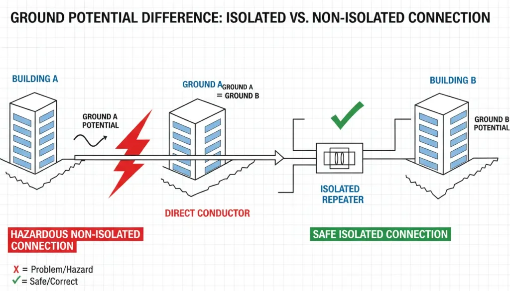
Caption: Isolation protects against ground potential differences.
Mistake 9: Connecting Directional Ports Backwards
The problem: Some repeaters have marked “Master” and “Slave” ports. Connecting them in reverse disables communication.
The solution: Read the manual. Connect the “Master” side toward the host controller and the “Slave” side toward field devices. If unsure, try swapping—it won’t damage the hardware.
Mistake 10: Daisy‑Chaining Power Through Repeaters
The problem: Powering one repeater and attempting to feed the next through the data cable causes voltage drop and may overload the first unit’s supply.
The solution: Power each repeater locally from a dedicated supply. If that’s impossible, use a separate power pair (as in some hybrid cables) and calculate voltage drop carefully.
Quick Reference: 10 Mistakes at a Glance
| Mistake | Typical Symptom | Fix |
|---|---|---|
| 1. Repeater at bus end | Weak signal, errors | Move to middle of network |
| 2. A/B swapped | No communication | Swap wires at one end |
| 3. Termination on repeater | Reflections, data loss | Disable internal term; terminate ends only |
| 4. Underpowering | Intermittent errors | Use 9‑24V regulated supply |
| 5. Shield grounded both ends | Ground loop noise | Ground shield at one end only |
| 6. Long stubs | Reflections | Keep stubs < 3 m |
| 7. Too many repeaters | Timeouts | Use fiber beyond 4 repeaters |
| 8. No isolation | Unexplained failures | Use isolated repeater (≥2500V) |
| 9. Wrong direction | No link | Check port labels |
| 10. Chained power | Voltage drop | Power each repeater locally |
Industrial Considerations
If your network operates in factories, outdoors, or between buildings, standard commercial repeaters may not survive. Look for:
- Temperature range: –40°C to +85°C
- Isolation: ≥2500V optical or transformer
- Power: 9‑24V DC terminal block (not barrel jack)
- Mounting: DIN rail compatible
- Surge protection: 2kV on signal lines
When you are looking for Products like the Valtoris 4CH‑HUB‑RS485 series you should check that they meet the specs you need. The Valtoris 4CH‑HUB‑RS485 series has some features, like 2500V isolation and it can work in really wide temperature ranges.. No matter what brand of Products you choose you should always check the datasheet, for the Products to make sure they will work in your environment.
Summary
RS485 repeaters are really things. They take a signal in. Then they send a clean copy of the RS485 signal out. Most problems with RS485 repeaters come from ignoring the rules for wiring an RS485 network.
Stick to the fixes, for your RS485 repeaters that are mentioned above and your multi-segment RS485 network will run reliably for years.
*Sources: TIA/EIA‑485 standard, Analog Devices application notes, Texas Instruments RS‑485 design guides (slla272d), Maxim Integrated application note 763, and field reports from industrial maintenance forums.*