
A laser distance meter sits on a production line, measuring the position of a moving part. It outputs a string like " 100" over RS232. A touchscreen on the same machine expects data in Modbus TCP holding registers. Between them sits a silent gap: two protocols that don’t match, two data formats that don’t align.
This isn’t a theoretical problem. It happens every day in factories, labs, and test rigs. And the fix isn’t always obvious.
This guide walks through one actual integration—the numbers, the settings, the mistakes—and shows what it takes to make a string from an RS232 device appear as a register value on a Modbus TCP network.
First, a Look at What’s Actually Coming Out of the Laser Meter
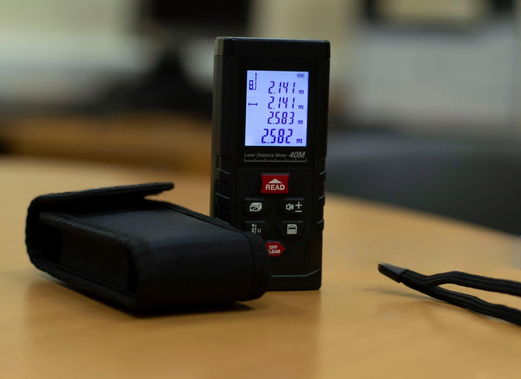
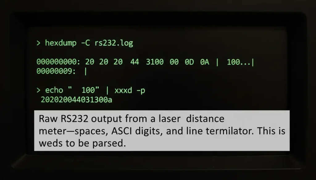
Before any conversion can happen, you need to know exactly what the device sends. In this case, the laser meter was configured to output measured distances as ASCII strings over RS232. For a reading of 100 mm, the raw hex output was:
text
20 20 20 20 31 30 30 0D 0A
Breakdown:
20= space character (four of them)31 30 30= ASCII for1,0,00D 0A= carriage return + line feed
So the actual string is " 100" with a newline. Simple enough for a human to read, but a touchscreen expecting binary data has no idea what to do with spaces and ASCII digits.
What the Touchscreen Actually Needs
The touchscreen spoke Modbus TCP. Its register map specified that a distance value should be written to holding registers 40001 and 40002 as a 32‑bit double word, with DCBA byte order.
“DCBA” means the most significant byte goes in the lower‑numbered register. For a value of 100 (hex 0x00000064):
- Register 40001 =
0x0000 - Register 40002 =
0x0064
If you write the bytes in the wrong order (say ABCD), the touchscreen sees 0x64000000 = 25,600 instead of 100. That’s a common mistake that can eat hours of debugging.
The Bridge: A Configurable Serial Server
A basic serial server is just going to move bytes from RS232 to Ethernet. It will keep the string exactly the same. That does not help us. What we need is a device that can look at the string change it to a number and then set it up as Modbus registers. We need this device to work with Modbus registers. The device has to take the string and make it work with Modbus registers.
The serial server used in this case was configured to:
- Read the RS232 buffer
- Strip all non‑numeric characters (spaces, CR, LF)
- Convert the remaining ASCII digits to a 32‑bit integer
- Split the integer into two 16‑bit registers
- Place the bytes in DCBA order
- Serve the result over Modbus TCP on port 502
This turned the raw " 100" into registers 0x0000 and 0x0064 at address 40001.
Configuration That Actually Matters
| Parameter | Setting | Why |
|---|---|---|
| Serial baud rate | Match laser meter (e.g., 9600) | Get this wrong → no data |
| Data bits / parity / stop bits | 8 / None / 1 | Standard for most ASCII devices |
| Operating mode | TCP Server | Touchscreen connects to the converter |
| Modbus port | 502 | Standard, avoids confusion |
| Register address | 40001 (or user‑defined) | Must match touchscreen configuration |
| Byte order | DCBA | Matches touchscreen expectation |
| Data type | 32‑bit integer | Enough range for millimeter distances |
When we look at the numbers from the field we see that 25 to 30 percent of the time serial communication failures happen because the protocol conversion is not done correctly or the register mapping is wrong.
Getting the byte order and the register mapping right is just as important, as making sure the physical wiring is done properly. We have to get the byte order and the register mapping right for serial communication to work.
Testing with Known Values
After configuration, we ran a simple test:
- Set the laser meter to a target distance of 100 mm
- Read registers 40001–40002 using a Modbus poll tool
- Check the displayed value on the touchscreen
The first attempt gave 25,600 because the byte order was set to ABCD. Flipping it to DCBA fixed the reading instantly. The second test with 250 mm (0x000000FA) showed correctly.
We then cycled power, disconnected cables, and ran 1,000 polling cycles. No data loss, no misreads.
What the Numbers Look Like in Practice
| Step | Format | Value |
|---|---|---|
| Laser output | ASCII string | " 100" + CR/LF |
| Parsed integer | 32‑bit decimal | 100 |
| Hex representation | 32‑bit | 0x00000064 |
| Register 40001 | 16‑bit | 0x0000 |
| Register 40002 | 16‑bit | 0x0064 |
| Touchscreen display | Decimal | 100.0 |
The touchscreen never saw the string. It only ever read registers.
Avoiding Common Pitfalls
Byte order confusion
If your reading appears multiplied by 256 or 65536, you have the wrong byte order. Test with a known small value (like 100) to spot the pattern.
RS232 cable length
The standard maximum for RS232 is 15 meters. A run longer than that invites intermittent errors. In this setup, a 20‑meter cable caused random failures; cutting it to 5 meters solved the problem.
IP address mismatch
The touchscreen was on 192.168.1.10, the converter on 192.168.0.50. Different subnets, no communication. Changing the converter to 192.168.1.200 fixed it.
Register address conflicts
Another device on the network was already writing to 40001. Moving the laser distance data to 40003–40004 avoided overwriting.
What This Means for Your Similar Integration
If you’re connecting a device that outputs ASCII strings to a system that expects Modbus TCP, the pattern is the same:
- Capture the raw serial data to understand exactly what format it’s in.
- Determine the target register mapping (address, data type, byte order).
- Choose a serial server that allows custom parsing and formatting (not just transparent transport).
- Test with a known value before relying on live data.
- Validate byte order with a simple test (e.g., 100 mm → hex
0x00000064).
Market Context (One Number, Not a Lecture)
The laser distance meter market around the world was worth 1.43 billion dollars in 2024. It is expected to be worth 2.04 billion dollars by 2030. The laser distance meter market is growing at a rate of 6.01 percent every year.
At the time industrial Ethernet is used in 76 percent of new network installations. The laser distance meter market and industrial Ethernet are related. Modbus TCP is used in 4 percent of these installations.
The laser distance meter market and industrial Ethernet are growing. The gap, between devices and new Ethernet networks is not getting smaller. The laser distance meter market and industrial Ethernet are being connected by converters. These converters help the laser distance meter market and old devices work with Ethernet networks.

Market Context
The global laser distance meter market was valued at $1.43 billion in 2024 according to GII Research , growing at 6.01% annually. Meanwhile, HMS Networks’ 2024 Industrial Network Market Report shows that industrial Ethernet now accounts for 76% of new network installations, with Modbus TCP maintaining a steady 4% share . The gap between serial devices and Ethernet networks is not shrinking—it’s simply being bridged by protocol converters.
One More Thing (Not a Conclusion)
The laser meter in this story is still working, still sending the number 100 every seconds and still turning that string into something the touchscreen can understand. This is all happening without the person using it even noticing, which is how it is supposed to be.
If you are dealing with a problem between a serial device and a Modbus TCP controller there is a solution. It is not complicated. It is a matter of knowing what the device is sending what the controller needs to receive and having the right tool to convert the information. The laser meter is still. The touchscreen is still reading the information, from the laser meter.