
RS485 can handle up to 32 devices on a single pair of wires—If you do the wiring correctly everything will work properly.. If you get it wrong you will waste a lot of time trying to find and fix problems that happen sometimes like messed up data or nothing working at all. The standards for wiring will tell you what to do. They do not tell you everything, about what happens when you are actually installing the wiring in a real place.
- Do I connect the shield at both ends or just one?
- My baud rate is 9600—how far can I really go?
- I have 25 devices; is that too many?
- Why do I get random data errors?
- Can I mix Modbus and Profibus on the same wire?
This guide gives you the answers you need with rules that really work, not just ideas. It is based on the RS485 standards. What people have learned from actually using it not just guesses.
1. Wiring Topology: Why Daisy Chain is the Only Reliable Way
RS485 was designed for one topology: daisy chain (also called bus topology). Every device connects to a single main trunk line, with short drop cables (stubs) connecting each device to the trunk .
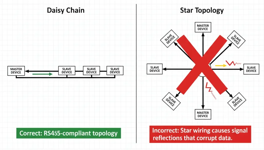
Why not star?
In a star topology, signals reflect off the end of each long branch. These reflections travel back to the main line and interfere with other signals. The longer the branch, the worse the reflection. This is physics, not opinion .
Rules for daisy chain:
- Keep stub length under 3 meters, ideally under 30 cm .
- Use one continuous cable from device to device.
- Avoid T-connectors or Y-splices—they create impedance mismatches.
What about other topologies?
If your site is already wired in star (common in older buildings), you have options:
- Use an RS485 hub at the center to isolate each branch .
- Use repeaters to segment the network.
But for new installs, daisy chain is always the first choice.
2. Maximum Distance and Node Count
RS485 is specified for up to 1200 meters at low speed (9600 bps) and up to 32 unit loads per segment . Modern transceivers with lower unit loads allow up to 256 devices on a single bus.
The relationship between speed, distance, and node count isn’t linear:
| Baud Rate | Max Distance (approx.) | Max Nodes (typical) |
|---|---|---|
| 9600 | 1200 m | 32–256 |
| 38400 | 800 m | 32–128 |
| 115200 | 400 m | 32–64 |
| 921600 | 100 m | 16–32 |
Values depend on cable quality, environment, and transceiver type .
Practical rule: If you need to go beyond these limits, use repeaters to segment the bus. Each segment gets its own termination and can support another 32-256 devices
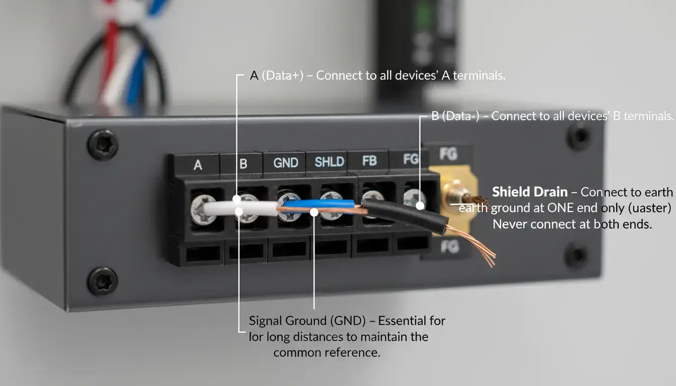
3. Physical Connections: A, B, GND, and Shield
RS485 uses two signal wires: A and B (sometimes labeled D+ and D-). For long distances, you also need a common ground and a shield.

A and B polarity:
- A (+) is typically the non‑inverting line.
- B (–) is the inverting line.
- Some manufacturers label them the opposite. If you get no communication, swap A and B at one end—it won’t damage anything.
Common ground (GND):
For long distances or when devices are powered separately, connect a third wire between the GND terminals. This keeps the signal reference voltage within the transceiver’s common‑mode range.
Shield:
- Use shielded twisted‑pair cable (impedance 120 Ω).
- Connect the shield at one end only, usually at the master side.
- Never ground both ends—it creates ground loops and invites noise.
4. Device Addressing: Unique IDs for Every Slave
When we talk about Modbus RTU, which’s the most common protocol for RS485 we need to make sure that each slave device has its own special address. This address has to be a number between 1 and 247. The address 0 is not, for any slave device it is used for sending messages to all devices at the time, which is called a broadcast. Modbus RTU uses this system to keep everything working.
Address conflicts cause:
- Intermittent communication failures
- Wrong device responding
- CRC errors
If you add or remove a device, verify its address doesn’t clash with any other.
5. Termination Resistors: When and Where
Signal reflections at the ends of the bus are avoided by termination resistors (typically 120Ω). They are impedance matching components for the cable and they are absorbing the power so it does not bounce back and corrupt incoming data.
When you need termination:
When you might not need termination:
- Short runs (< 300 m) at low speeds (< 38.4 kbps)
- Rule of thumb: if the one-way propagation delay is less than 10% of the bit time, termination may be omitted
Where to put termination:
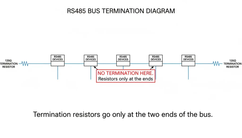
Some devices have termination resistors that are already built in. You can turn these termination resistors on using a DIP switch. Only use the devices with termination resistors if they are, at the end of something.
6. Bias Resistors: Keeping the Bus Quiet
During idle states when no device is transmitting, the RS485 bus floats. This undefined voltage state can be misinterpreted by receivers as false start bits, causing junk data. To prevent this, fail-safe bias resistors (typically 4.7 kΩ) are used to pull line A high and line B low, ensuring a defined idle state across the network.
7. Protocol Requirements: They Must Match
RS485 defines only the physical electrical layer; it does not dictate the data format. Therefore, all devices on a single bus must speak the exact same higher-level protocol (e.g., Modbus RTU, Profibus DP, or ASCII).
Critical requirements for Modbus RTU:
- All devices must have the same baud rate
- Same word size (usually 8 bits)
- Same parity (none, even, odd)
- Same stop bits (usually 1)
Can you mix Modbus and Profibus?
No Profibus DP is not compatible, with Modbus RTU even though both Profibus DP and Modbus RTU run on RS485. The thing is, Profibus DP and Modbus RTU use framing they use different timing and they also use different error handling.
If you have devices with different protocols, you need separate RS485 ports or gateways.
8. Troubleshooting: When It Doesn’t Work
Here’s a systematic approach to RS485 problems, from physical to application layer.
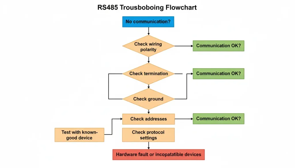
The A/B swap trick is really useful. Sometimes manufacturers do not label the A and B wires in a way. So when you do not get any response the first thing you should try is swapping the A and B wires. This can often fix the problem with the A and B wires.
Testing tools:
- Multimeter (check voltage between A and B—idle should be >200 mV)
- Oscilloscope (see reflections and signal quality)
- Modbus diagnostic tools like ModScan or Modpoll
9. Data Aggregation: Getting All That Data to One Place
Once you have multiple RS485 devices talking, you need to get their data to a computer, PLC, or cloud platform. Here are the common approaches:
Option A: Direct PC connection
- Use a USB-to-RS485 adapter for temporary debugging
- Limited by USB cable length and PC location
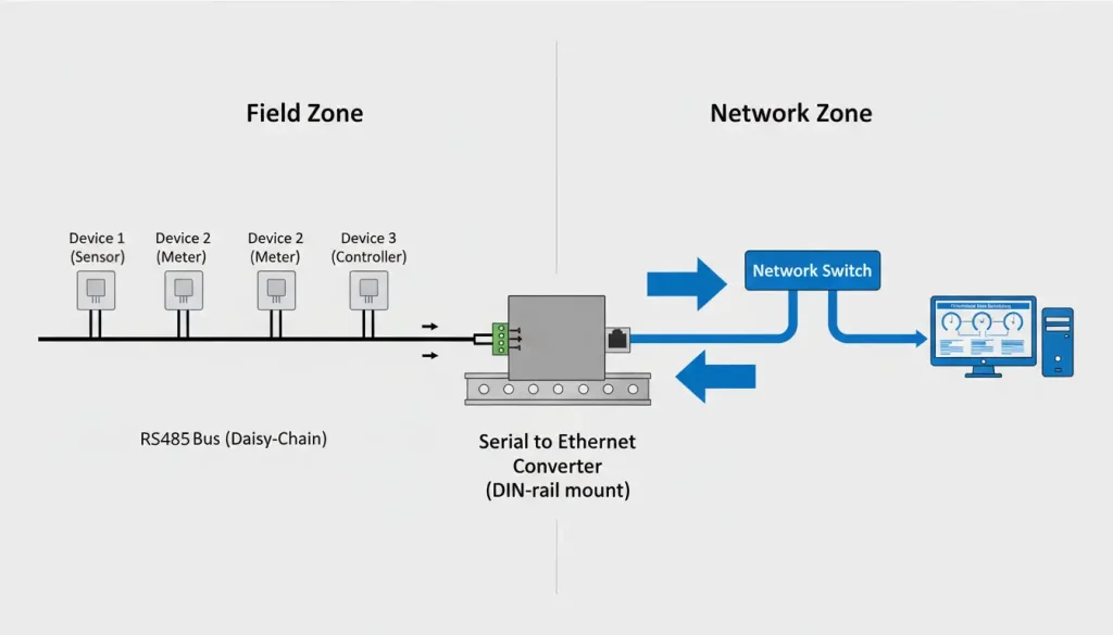
Option B: Serial to Ethernet converter
- Connect the entire RS485 bus to a serial device server
- The device server makes the serial data available over TCP/IP
- Multiple PCs can access the same data over the network
Option C: Multi-port RS485 hub
- If you need to isolate different segments or create star topologies
- Built-in isolation prevents ground loops
- Each port can drive its own bus segment
Option D: Industrial gateway
- Combines RS485 conversion with protocol translation (e.g., Modbus RTU to MQTT)
- Can send data directly to cloud platforms
Devices like the Valtoris 1CH-RS485-ETH or 2CH-RS485-ETH fall into the second category—they take the entire RS485 bus and make it accessible over Ethernet, with industrial features like wide temperature range (-40°C to 85°C), 2KV surge protection, and DIN rail mounting.
10. Isolation: When and Why You Need It
Ground loops are bad news for RS485 networks. This is because when you have devices in buildings or they are plugged into different power sources the ground voltage can be very different. It can be off by much as tens of volts. This is a problem for RS485 networks and it is called a ground loop. Ground loops can cause a lot of trouble, for RS485 networks.
Symptoms of ground loop problems:
- Intermittent errors that change with weather or equipment operation
- Unexplained device failures
- Data corruption that disappears when you disconnect the ground wire
The solution: isolation
Galvanic isolation breaks the electrical path between devices while allowing data to pass through optocouplers or capacitive barriers .
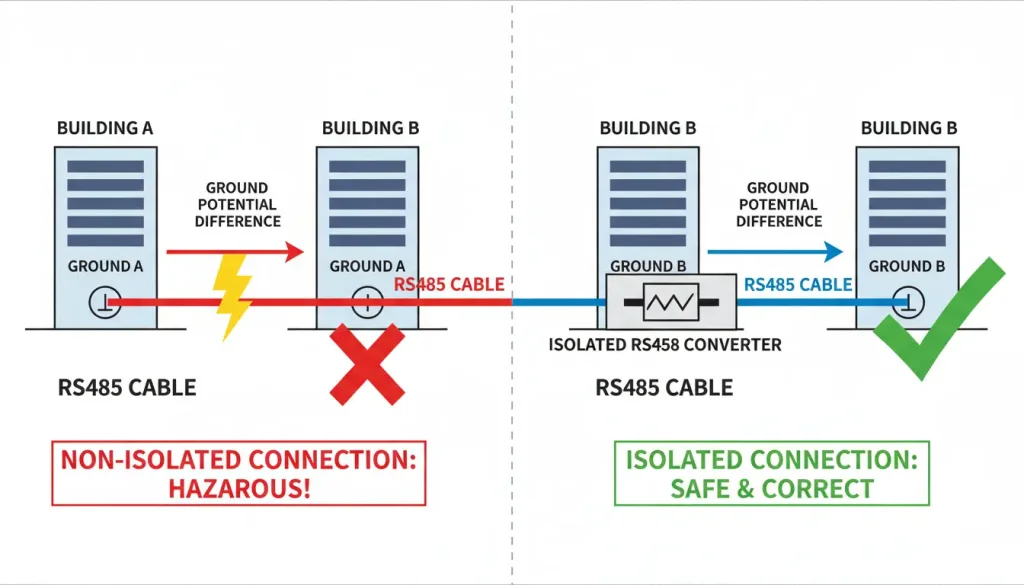
IndIntegrating RS485 devices with built-in galvanic isolation, such as the Valtoris series, is the most robust defense. Featuring 1500V to 3000V isolation, these modules physically sever the electrical path, blocking destructive ground loop currents and transient voltage spikes from frying your PLC ports and connected sensors.
Quick Reference Summary
| Topic | The Rule |
|---|---|
| Topology | Daisy chain only. Stubs < 3 m. |
| Wiring | A to A, B to B. Ground at one point. |
| Termination | 120Ω at both ends for long runs. |
| Addresses | 1-247, unique per device. |
| Protocol | All devices must match (baud rate, parity, etc.). |
| Troubleshooting | Swap A/B first. |
| Distance | 1200 m at 9600 bps; less at higher speeds. |
| Nodes | 32 per segment (up to 256 with low-load devices). |
| Isolation | Required for different buildings or large ground shifts. |
RS485 is a robust, reliable standard when you follow the rules. The problems come from bending those rules—star wiring, missing termination, ground loops, or mismatched protocols. Stick to the basics, and your multi-drop network will run for years.
Frequently Ask Questions
Q: Can I use standard Cat5e or Cat6 Ethernet cable for an RS485 network instead of specialized serial cable?
A: Yes, for most short to medium industrial runs, Cat5e/Cat6 works well because it is twisted pair cable with an impedance (100Ω) close enough to the RS485 standard (120Ω). The absolute rule: You must use a single twisted pair (e.g., the solid blue and striped blue wires) for the A and B signals. Never split A and B across different color pairs, or you will lose the noise-canceling benefits of the twist. For extreme distances or high-EMI environments, Belden 9841 or equivalent RS485-specific cable is still required.
Q: I have a 4-wire serial device (TX+, TX-, RX+, RX-). How do I connect it to my 2-wire RS485 bus?
A: A 4-wire device is typically RS422 (full-duplex). To adapt it to a 2-wire RS485 network (half-duplex), simply jumper (short) the positive terminals together (TX+ connected to RX+) to form your new “A” line, and jumper the negative terminals together (TX- connected to RX-) to form your “B” line. Ensure the end device’s configuration allows for half-duplex operation, meaning it knows to disable its transmitter while receiving.
Q: The guide says all devices must share the same baud rate. What if I have one legacy device stuck at 9600 bps, but my main SCADA bus runs at 115200 bps?
A: You can’t use different baud rates on the same physical wire because it will mess up the bus. To fix this without slowing down your whole network, you need to separate the slow device. Connect the old 9600 bps device to a special port on a Industrial Serial-to-Ethernet Converter . This device will handle the slow polling on its own and quickly convert the data into high-speed Modbus TCP for your SCADA system.
Q: If I am forced to use a star topology due to existing building wiring, how exactly does an RS485 Hub prevent the signal reflection you mentioned?
A: If you just splice three wires together (a T-tap or star), the signal hits the end of each branch and bounces back, causing massive data collisions. An RS485 Isolated Hub prevents this by acting as a traffic cop. It takes the main signal and actively regenerates (repeats) it down each individual branch on physically isolated circuits. This tricks each branch into acting like its own independent, clean point-to-point network, completely containing the reflections.