
Engineers managing industrial automation, medical telemetry, or military radar systems inevitably hit a physical wall. Copper wiring—the backbone of legacy serial communication—was never designed for the harsh realities of modern infrastructure. When you route data across a factory floor packed with heavy machinery, or attempt to connect two buildings kilometers apart, pure electrical signals begin to degrade, distort, and fail.
If it’s a garbled PLC screen, a communication board fried after a thunderstorm, or struggling to push data past the rs232 cable length limit, the root cause is almost always the physical medium itself. Copper is an antenna for noise. The best integrators have opted for a final solution of converting the serial electrical signals to pulses of light using a serial to fiber converter. In this deep dive, we’ll explore the physics of communication failures and how pushing RS232 over fiber and RS485 over fiber resolve these bottlenecks across four critical industries.
🛠️ Interactive Troubleshooting: Is Copper Failing Your Network?
Select the symptoms your serial network is experiencing to see the underlying physical cause.
Beyond Copper: The Physics Behind RS485 and RS232 Limitations
First, system integrators need to understand why the failure occurs before they can fix it. Serial protocols such as RS232 and RS485 are defined by electrical characteristics. RS232 uses unbalanced , single-ended voltages with reference to a common ground . Which makes it very sensitive to noise. At a modest 19200 bps, the standard rs232 cable length limit is effectively limited at 15 meters ( 50 feet ) . Push it further and the capacitance of the cable degrades the square waveforms to unrecognizable curves.
RS485 improves on this by using differential signaling, sending the same data across two wires in opposite voltage polarities. This common mode noise rejection is robust but still copper-dependent. The theoretical max distance of rs485 is around 1200 meters (4000 feet). But this rating is based on a pure, lab-like environment. In practice the effective range is substantially reduced by wire resistance, capacitance and localized electromagnetic fields.
| Transmission Medium | Standard Max Distance | EMI / RFI Immunity | Ground Loop Risk |
|---|---|---|---|
| RS232 (Copper) | 15 Meters | Very Low | High |
| RS485 (Copper) | 1,200 Meters (Theoretical) | Moderate | High (if unisolated) |
| Multi-Mode Fiber | 2,000 Meters | Absolute (100%) | Zero Risk |
| Single-Mode Fiber | 20,000+ Meters | Absolute (100%) | Zero Risk |
Industrial Environments: Killing VFD Interference and Ground Loops
RS485 improves on this by using differential signaling, sending the same data across two wires in opposite voltage polarities. This common mode noise rejection is robust but still copper-dependent. The theoretical max distance of rs485 is around 1200 meters (4000 feet). But this rating is based on a pure, lab-like environment. In practice the effective range is substantially reduced by wire resistance, capacitance and localized electromagnetic fields.
When an engineer complains about RS485 interference on a PLC forum, it is almost always related to VFDs. Every time a heavy motor kicks on, the RS485 data strings from nearby temperature sensors or flow meters turn into unreadable garbage. Additionally, when equipment is spread across a massive factory, the electrical ground potential at panel A is rarely the exact same voltage as the ground at panel B. This creates a “Ground Loop,” causing unwanted current to flow through the shielding of the RS485 cable, severely corrupting data.
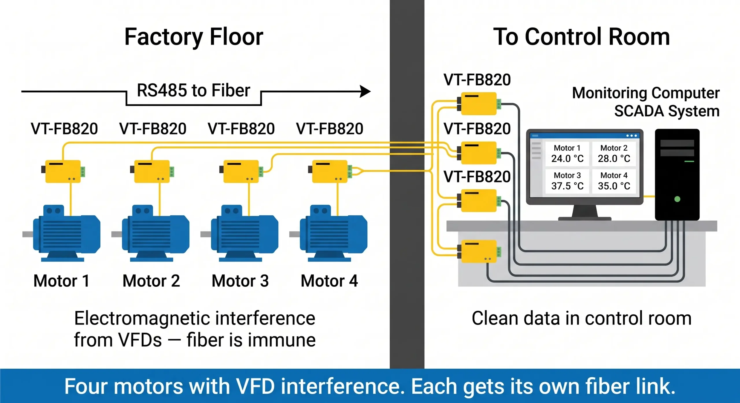
The only mathematically correct way to solve this is to add an RS485 to fiber solution. The magnetic field cannot influence the photons moving in the glass fiber. Dielectric isolation is required by the IEEE Standard 1100 for powering and grounding sensitive electronic equipment in industrial environment. Fiber optics provide unlimited dielectric isolation, eliminating ground loops there, so VFD interference is a non-issue.
Outdoor & Cross-Building: Surviving Lightning and Distance Drops
Consider a large industrial campus, a water treatment facility, or an oil pipeline. You need to control a network of 20 PTZ (Pan-Tilt-Zoom) security cameras located 1.5 kilometers away from the central command room. The cameras accept RS485 telemetry for movement control.
Attempting to string copper RS485 across multiple outdoor structures is a massive liability. Not only will the signal decay past the rs485 max distance, making the far-end cameras unresponsive, but outdoor copper acts as a massive lightning rod. A nearby lightning strike can induce thousands of volts into the RS485 line, traveling straight into the control room and incinerating the main DVR or PLC motherboards.
| Failure Symptom | Underlying Root Cause | Fiber Optic Resolution |
|---|---|---|
| Random data drops when machinery operates | Electromagnetic Interference (EMI) from VFDs/Motors | Photons in glass are immune to magnetic fields. |
| Devices work locally but fail at 1500m | Cable capacitance distorting the square wave (Attenuation) | Light experiences near-zero attenuation over standard distances. |
| Burnt serial ports on PLCs after a storm | Lightning-induced surges or Ground Potential Difference | Glass is non-conductive; surge paths are physically severed. |
Medical Compliance: Achieving IEC 60601-1 Dielectric Isolation
The medical sector operates under strict life-safety regulations. Consider an MRI room. The MRI machine generates magnetic fields measured in Teslas—powerful enough to turn a metal wrench into a lethal projectile. No ferrous metals or standard copper cables can safely exist in the active zone.
Furthermore, medical devices that connect to patients (like telemetry systems or ventilators) are governed by the IEC 60601-1 standard, which mandates stringent limits on allowable leakage currents. If an external monitoring computer experiences a fault, an electrical surge must not be allowed to travel down a serial cable into the patient-connected machinery.
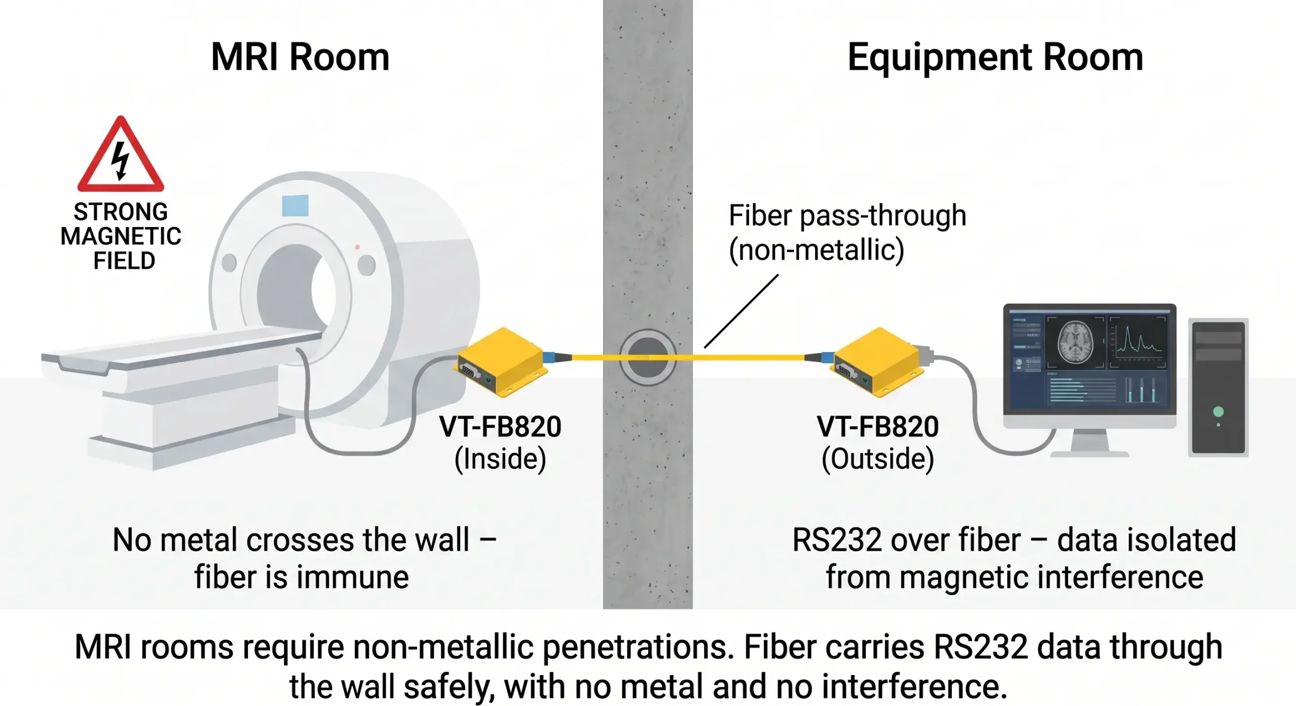
By routing rs232 over fiber, hospital engineers solve two problems simultaneously. First, the fiber cable contains zero metal, making it perfectly safe for the MRI suite. Second, the glass core acts as an absolute dielectric barrier, guaranteeing 100% compliance with IEC 60601-1 electrical isolation requirements. The data flows reliably, and the patient is completely protected from electrical faults.
Military & Aerospace: Securing Data Against EMP and Tapping
In tactical deployments, the rules of communication change. Imagine a military outpost requiring real-time radar data from a hilltop installation 3 kilometers away. The terrain is rugged, but more importantly, electronic warfare (EW) and signal jammers are active in the sector.
Standard wireless communication is out of the question due to jamming and interception risks. Running copper wire exposes the outpost to two critical threats: first, copper wire radiates RF signals as data travels through it, which can be intercepted using non-intrusive induction coils by hostile forces. Second, in the event of an Electromagnetic Pulse (EMP), all unshielded copper lines act as antennas, capturing the pulse and destroying the connected military hardware.
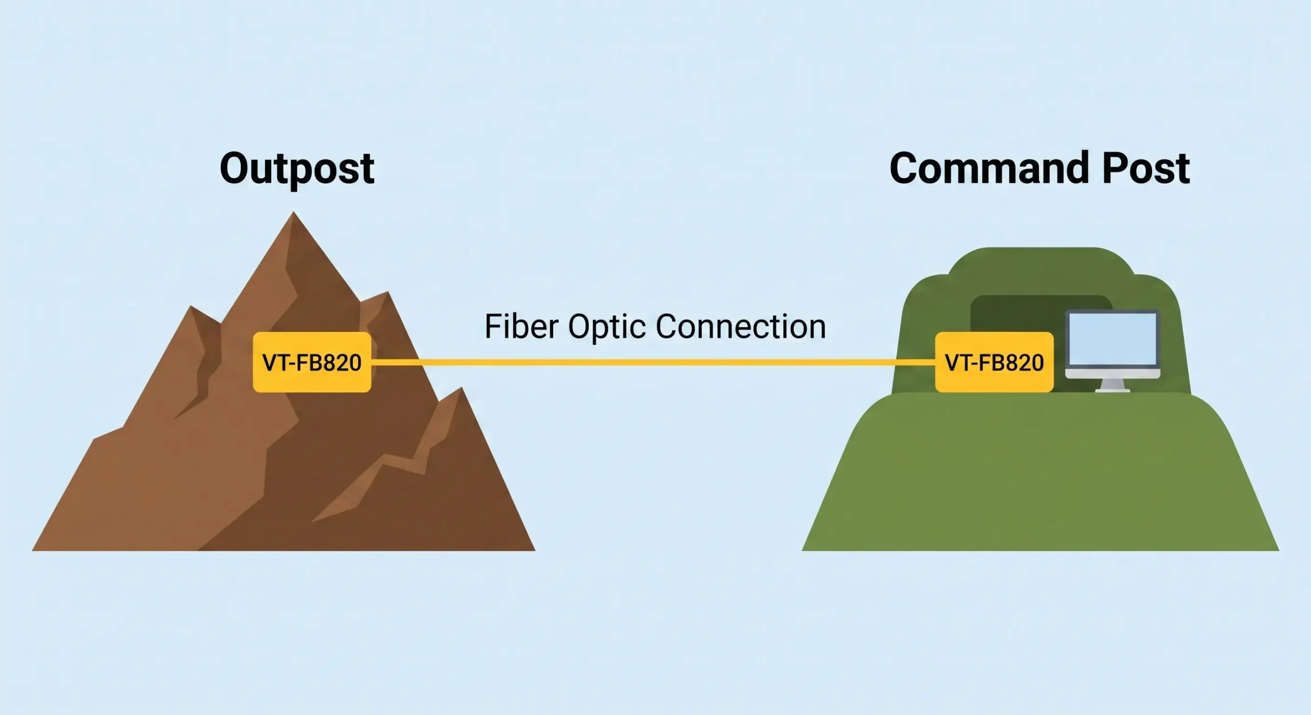
Fiber optics emit zero electromagnetic radiation, making them physically impossible to “tap” without breaking the glass and triggering immediate link-loss alarms. Furthermore, being non-conductive, fiber is entirely immune to EMPs. A pair of industrial-grade converters passing data over single-mode fiber guarantees secure, unjammable, and survivable communication across the battlefield.
WDM Technology: How Single-Fiber Converters Halve Your Infrastructure Costs
Previously, to convert serial data to optical signals, it required two separate fiber strands, one for transmit (Tx) and one for receive (Rx). Fiber cable has gotten cheaper but trenching, laying conduit and terminating cables is still the largest capital expenditure (CapEx) in any network installation.
In modern industrial converters, Wavelength Division Multiplexing (WDM) is used. With WDM technology, two-way communication can occur on a single strand of glass. It does this using two different wavelengths (colors) of light. For example, the “A-End” device transmits data using a 1310nm laser and receives data using a 1550nm laser. The corresponding “B-End” device does the opposite – it transmits at 1550nm and receives at 1310nm.
| Metric | Traditional Dual-Fiber | Single-Fiber WDM (e.g., VT-FB820) |
|---|---|---|
| Cable Required | 2 Strands (Tx / Rx) | 1 Strand (Bi-Directional) |
| Infrastructure Cost | High (Double the termination points) | Low (Halves cable and splicing costs) |
| Wavelengths | Same wavelength on both strands | 1310nm and 1550nm alternating |
| Ordering Logic | Any unit connects to any unit | Must order matched “A” and “B” pairs |
Serial to Fiber Converter Procurement Checklist: Key Specs
Not all converters are created equal. When specifying equipment for an industrial layout, system integrators must determine exactly how the data needs to be accessed at the control center. The decision usually boils down to two distinct topologies: pure hardware point-to-point, or network-integrated.
1. Point-to-Point Extension (Hardware Decoding)
If your goal is simply to act as a “virtual cable” to extend an RS485 bus or push past the rs232 cable length limit without altering your existing SCADA or PLC logic, you need a pure media converter (like the VT-FB820). These devices rely on hardware-level decoding. Because they do not buffer the serial data to convert it into complex network packets, they boast a near-zero transmission delay. Furthermore, they feature Auto-Baud Rate Detection (up to 115200bps). You do not need to configure stop bits, parity, or IP addresses; you simply wire the terminals, and it works. This is strictly plug-and-play.
2. Network Integration (TCP/IP Conversion)
If you have an RS485 device in the field, but you want to monitor it directly from a centralized server room using a standard Ethernet switch, a standard media converter won’t work. You need a device that acts as a Serial Server over Fiber (like the VT-FB810). These devices actively take the RS485 data, package it into TCP/IP or UDP formats, and send it down the fiber optic line to be digested by standard Ethernet network switches and Virtual COM port software on your PC.
| Feature / Requirement | Pure Media Converter (VT-FB820) | Serial-to-Fiber Server (VT-FB810) |
|---|---|---|
| Primary Function | Extends serial signal purely via light | Converts serial to TCP/IP over fiber |
| Configuration Required | None (Plug and Play / Auto-Baud) | IP Address, Baud Rate, TCP Client/Server |
| Network Switch Compatibility | No. Must be used in pairs (Point-to-Point) | Yes. Can plug directly into fiber network switches |
| Transmission Delay | Near Zero (Hardware decoded) | Slight (Requires TCP/IP packet framing) |
*Note: When procuring, ensure the hardware supports wide temperature ranges (-40°C to 85°C) and wide voltage inputs (9~24V DC) to survive unconditioned outdoor cabinets.
Ready to Eliminate RS485 Interference?
Choose the right architecture for your industrial network:
VT-FB820
Need Plug-and-Play Point-to-Point?
Pure media converter with hardware decoding. Zero transmission delay, auto-baud rate detection. Perfect for direct serial extension without any network configuration.
VT-FB810
Need Network/TCP Integration?
Serial device server over fiber. Converts serial to TCP/IP for seamless remote access. Plugs directly into your existing IT fiber network switches.
Field Troubleshooting: Multimeter Testing for RS485 Over Fiber
Before ripping out your copper infrastructure to install a serial to fiber converter, you must verify the electrical integrity of your RS485 lines. Many engineers mistakenly blame the fiber converter when the underlying issue is a bad RS485 termination at the PLC.
You can perform a quick diagnostic using a standard digital multimeter set to DC Voltage. Measure the lines while the network is idle (no active data transmission):
| Test Points | Expected Voltage Range | What It Indicates If Out of Range |
|---|---|---|
| Data A to Ground (GND) | +2.5V to +3.5V | Short to ground or excessive cable capacitance. |
| Data B to Ground (GND) | +1.5V to +2.5V | Line B is shorted, or the VFD interference has induced a massive standing voltage. |
| A to B (Differential) | +200mV to +5V (Positive) | If negative or near zero, your A and B lines are reversed, or the biasing resistors are failing. |
If your multimeter readings wildly fluctuate when a nearby VFD or motor starts, you have definitive proof of Electromagnetic Interference (EMI). At this point, deploying a hardware-decoded fiber converter (like the VT-FB820 series) is mandatory to isolate the A and B lines from the induced noise.
Protocol Timing: Calculating Modbus RTU Latency Over Fiber
The most common industrial protocol over RS485 is Modbus RTU. Modbus RTU is time sensitive. The Modbus specification says a message is complete when there is a 3.5 character silent gap on the bus. A serial to fiber converter with too much processing latency can inadvertently split a Modbus frame and cause the PLC to drop the packet with a timeout error.
This is why understanding the topology of your fiber converter is critical:
- Standard Serial Device Servers (TCP/IP Conversion): These devices read the incoming RS485 data, buffer it in a standard 1500 byte Ethernet frame and transmit it over the fiber. This buffering process intentionally adds a few milliseconds of latency. If you are routing data through a network switch such as the VT-FB810, you may need to adjust the timeout settings on your PLC to account for the framing delay.
- Hardware-Decoded Media Converters: Pure point-to-point converters (e.g. VT-FB820) don’t use TCP/IP. Instead of waiting to collect 8 bits, they use serial hard decoding technology, shuttling individual bits of information directly to the optical laser. This results in almost zero transmission delay, maintaining the strict 3.5 character gap required by Modbus RTU .
Single-Mode vs. Multi-Mode: Matching Fiber to Your Project Scale
The final step in your network design is choosing the correct glass. Optical fiber comes in two primary variations, and your media converters must match the fiber type you install.
Multi-mode fiber has a larger core diameter (typically 50 or 62.5 microns). Because the core is wide, light bounces off the edges at multiple angles (modes) as it travels. This causes “modal dispersion,” where the light pulses blur together over long distances. Multi-mode is generally cheaper for the transceivers but is strictly limited to short runs (usually under 2 kilometers), making it fine for intra-building connections.
Single-mode fiber has a microscopic core (around 9 microns). The light travels straight down the center in a single beam without bouncing. This eliminates modal dispersion entirely. Single-mode fiber is the industry standard for industrial, municipal, and military installations because it easily supports 20-kilometer distances without any signal degradation, making it the superior choice for extending RS232 over fiber across vast expanses.
| Specification | Single-Mode Fiber (SMF) | Multi-Mode Fiber (MMF) |
|---|---|---|
| Core Diameter | 9 µm | 50 µm or 62.5 µm |
| Light Propagation | Single direct path (No bouncing) | Multiple paths (Bouncing off core walls) |
| Maximum Distance | 20+ Kilometers (Excellent for outdoors) | Up to 2 Kilometers (Strictly indoors/campus) |
| Typical Wavelengths | 1310nm, 1550nm | 850nm, 1300nm |
