

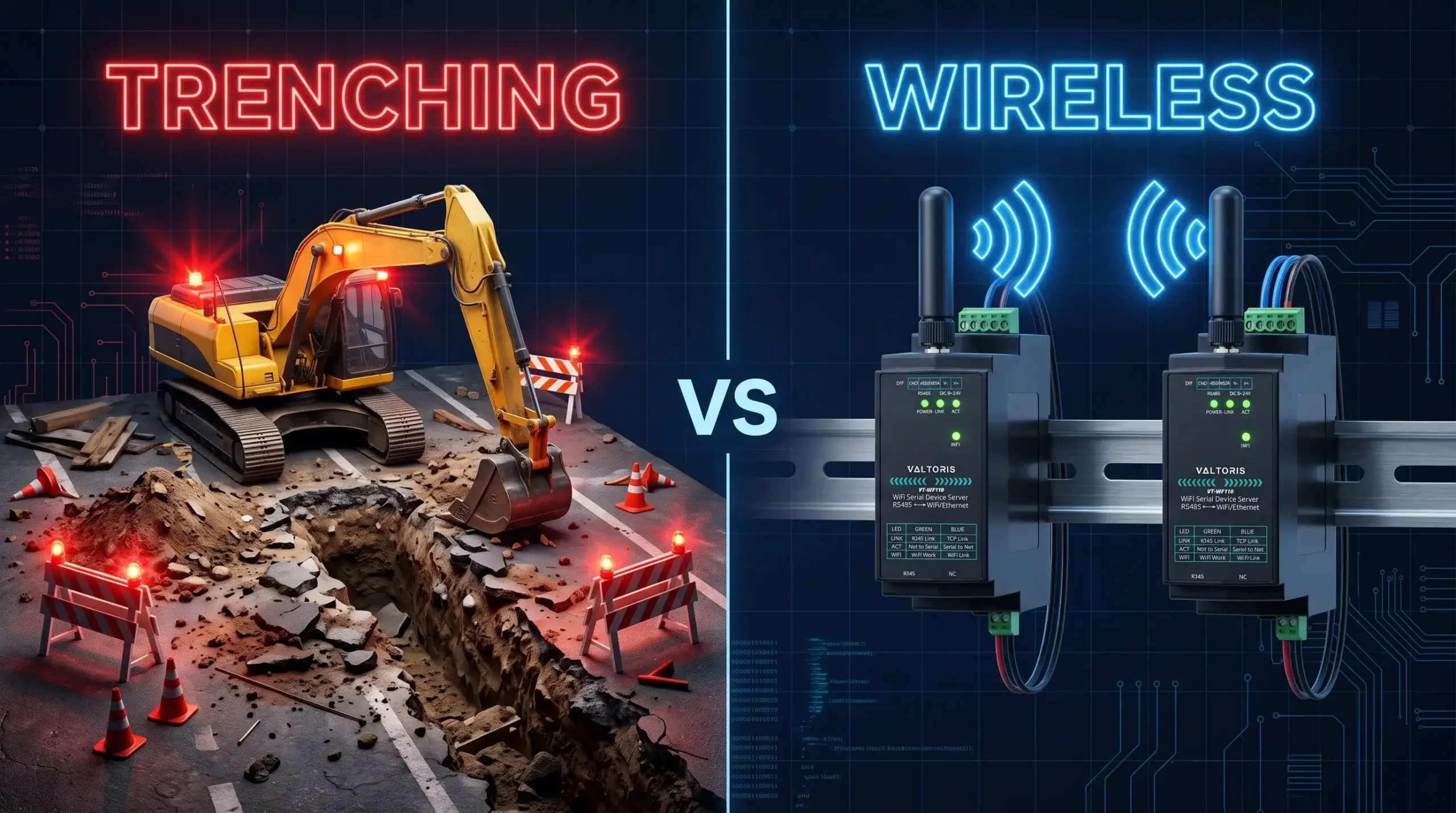
To span RS485 networks across physical barriers, like separate buildings, concrete or asphalt, usually requires prohibitively expensive trenching. In contrast, critical Operational Technology (OT) data sent over a busy corporate Wi-Fi network often results in dropped packets and Modbus polling timeouts.
The most practical solution is to install a dedicated point-to-point wireless RS485 bridge. It is a transparent, deterministic serial cable between machines that operates completely independent of the facility’s IT infrastructure. This manual describes a simple, unbiased approach to convert physical RS485 wiring to dedicated RF links to keep the Modbus RTU data stable, secure and isolated.
Contents Guide
- The Real Cost of Trenching: Wireless ROI
- 900MHz vs. 2.4GHz: The Right Tool for the Job
- Beating the “Polling Timeout” over Radio Links
- Transmitting RS485 Over WiFi in Plain English
- Building Your Virtual Cable: The Complete Setup Guide
- Testing, Validating, and Troubleshooting
- Beyond Two Devices: Multi-Site Topologies
- Frequently Asked Questions
Interactive Guide
Select your current objective to jump directly to the solution.
The Real Cost of Trenching: When to Choose an RS485 Wireless Bridge
In automation, the decision to go wireless is rarely driven by novelty; it is an economic and logistical necessity. According to the ACEEE technical report on Wireless Sensor Cost-Savings, eliminating conduit and physical wire routing can reduce industrial installation costs by up to 80%. When routing a simple twisted pair requires cutting through active driveways, navigating overhead cranes, or shutting down a production zone, the math heavily favors an RF bridge.
| Deployment Factor | Hardwired RS485 (Trenching/Conduit) | P2P Wireless Bridge |
|---|---|---|
| Material & Labor Cost | High ($50–$150 per meter for cutting/conduit) | Fixed Hardware Cost (Hardware only) |
| Deployment Time | Days to Weeks (Permits, concrete curing) | Minutes to Hours (Mounting and pairing) |
| Operational Downtime | Significant (Zone closures required) | Zero |
| Ground-Loop Risks | High (Requires optical isolation between distant buildings) | None (Air gap guarantees 100% galvanic isolation) |
Scenario A: 100m Asphalt Trenching
Includes cutting, conduit, pulling shielded twisted pair, repaving, and estimated 8 hours of facility downtime.
Scenario B: 2.4GHz Point-to-Point
One pair of industrial wireless serial converters. Installed on existing poles/panels in 30 minutes. Zero downtime.
900MHz vs. 2.4GHz: The Right Tool for the Job
A common mistake is assuming 2.4GHz Wi-Fi is the universal answer. While it offers excellent bandwidth for fast Modbus polling rates, 2.4GHz wavelengths are short and struggle to penetrate dense obstacles like reinforced concrete walls or steel tanks. If your physical layer is mismatched to your environment, no amount of software configuration will stabilize your wireless RS485 communication.
| Protocol | Max Range (LOS) | Network Topology | Best Application Scenario |
|---|---|---|---|
| Wi-Fi (2.4GHz) | ~300 Meters | Point-to-Point | High-speed Modbus RTU polling across open factory floors. (Focus of this guide) |
| LoRa (Sub-1GHz) | Up to 5 Kilometers | Point-to-Multipoint | Penetrating concrete walls or connecting remote outdoor pump stations. |
| Zigbee (Mesh) | Node-dependent | Self-healing Mesh | Complex layouts requiring AES encryption and multi-node signal relays. |
Valtoris VT-WF110: The Ultimate Modbus Wi-Fi Gateway
Bypass the factory router entirely. As an industrial-grade RS485 Wi-Fi bridge, the VT-WF110 features an integrated Modbus TCP to RTU engine, allowing you to establish a secure, deterministic Modbus RF tunnel without rewriting your SCADA polling logic.
Beating the “Polling Timeout”: Modbus RTU over Radio Links
The number one complaint on PLC forums for wireless bridges is the dreaded Modbus polling timeout. Engineers tend to instinctively blame the hardware. The root cause is usually a misunderstanding of how serial framing is treated during RF transmission.
Modbus RTU is a strictly timed protocol. The Modbus Organization specifies a silent gap of 3.5 character times to signal the end of a frame. When a serial server converts RTU data to TCP/IP packets and sends it over Wi-Fi, “Packet Assembly Delay” (typically 10ms–50ms) is introduced. This latency fractures the frame and you get a CRC error. If the Master PLC expects an immediate hardwired response, the timeout is inevitable.
The solution is not to buy a more expensive radio, but to properly optimize your SCADA or PLC Master polling parameters.
| Master Setting | Hardwired Baseline | Wireless Recommendation | Why It Matters |
|---|---|---|---|
| Response Timeout | 100 ms | 500 – 1000 ms | Accounts for RF modulation, IP routing, and airwave collision avoidance. |
| Inter-Frame Delay | 10 ms | 50 ms | Prevents the master from sending a new query before the slave’s wireless response arrives. |
| Retries | 0 – 1 | 2 – 3 | RF signals can be momentarily blocked by moving forklifts; a retry prevents a hard fault. |
The Hardware Fix: Edge-Level Storage Modbus Gateways
While modifying SCADA timeouts is a valid software workaround, high-frequency industrial polling requires a deterministic hardware solution. This is where advanced modules like the VT-WF110 outperform basic transparent bridges.
The VT-WF110 features a native “Storage Modbus Gateway”. Instead of exposing the Master PLC to wireless network jitter, the gateway actively polls the local RS485 devices and temporarily stores the register data in its internal cache. When transmitting Modbus over WiFi, the SCADA master sends a TCP query, and the VT-WF110 responds directly from its cache—typically within 3ms. This completely insulates the RS485 bus from Ethernet latency and permanently eliminates polling timeouts.
Crucial Advantage: Absolute Baud Rate Decoupling. Unlike a simple bridge where the serial settings at both ends need to match, a Storage Gateway buffers the data. This permits your local RS485 loops to work independently. You can easily connect a legacy PLC (e.g. 9600 bps) to a fast remote sensor (e.g. 115200 bps) and immediately solve hardware compatibility issues.
*Engineering Note: What about Write commands? The VT-WF110 is intelligent. While Read requests (FC 03/04) are served instantly from the cache, Write requests (FC 05/06) dynamically bypass the cache and are transmitted directly to the end-device to ensure real-time actuation of valves and relays.*
Transmitting RS485 Over WiFi: Point-to-Point in Plain English
To have a connection that goes from one point to another without latency spikes, we must bypass the factory IT infrastructure. Standard Wi-Fi routers act like traffic lights on a congested road; they route packets through centralized switches, increasing the risk of network jams.
The correct method is to configure one wireless module to act as the network host (Access Point) and the other as the Client (STA). They create a small, private, and direct RF tunnel. For serial data, this dedicated link acts exactly like a transparent copper wire.
Building Your Virtual Cable: The Complete Setup Guide
A true “cable replacement” means the wireless bridge must be totally transparent to your PLCs. We’ll use the Valtoris VT-WF110 as our benchmark to walk through the physical and network setup of two identical converters (Unit A and Unit B).
Step 1: Physical RS485 Wiring (Pin-to-Pin)
Before touching the software, you must wire the physical layer correctly. RS485 is a 2-wire differential bus. A common mistake is crossing the data lines. Match the terminals exactly as follows:
Pro Tip 1 (Wiring): If you are going over 200 Meters on your communication on the local copper side before the wireless bridge, make sure you have a 120 Ohm Termination Resistor across T+ and T- to avoid signal reflection.
Pro Tip 2 (RF Placement): Never leave the antenna inside a metal control cabinet. Metal enclosures act as Faraday cages. You must use a magnetic antenna extension cable to mount the antenna on the outside of the metal panel to ensure Line of Sight (LOS).
Step 2: Network & Serial Parameter Binding
To configure the units, power them up and connect your laptop to the converter’s LAN port using an Ethernet cable. Use web browser to login to the Web GUI (e.g. 192.168.1.200) using the default IP address. Now we construct the RF tunnel with the following parameters.
Note: If playing with subnets and TCP ports is not high on your list, industrial vendors often sell Pre-paired Kits with the AP/STA roles and MAC bindings locked down at the factory, so you can skip these software steps completely.
P2P Wireless RS485 Configuration Matrix
| Parameter | Unit A (The “Hub”) | Unit B (The “Client”) |
|---|---|---|
| WiFi Mode | AP Mode (Hidden SSID) | STA (Client) Mode |
| IP Address | 192.168.2.1 | 192.168.2.2 |
| Operating Mode | TCP Server | TCP Client |
| TCP Port | Local Port: 502 | Target IP: 192.168.2.1 Target Port: 502 |
⚠️ Critical Setup Rule: Serial Synchronization
A wireless bridge only replaces the copper wire; it does not translate baud rates. The Serial Baud Rate, Data Bits, and Parity (e.g., 9600, 8, N, 1) configured in the Web GUI of both Unit A and Unit B must be absolutely identical, and they must perfectly match your PLC and Sensor. A mismatch here will result in a solid TCP connection (green lights) but completely garbled data.
Testing and Validating Your Direct Link
Before leaving the site, perform a Serial Loopback Test. Connect the TX and RX pins on Unit B (the remote side). Connect your laptop via a USB-to-RS485 adapter to Unit A. Using a terminal program (like PuTTY), type characters. If they echo back instantly, your transparent bridge is functionally perfect.
| Symptom | Probable Cause | Corrective Action |
|---|---|---|
| LINK LED is Off | TCP Connection failed to establish. | Check Unit B Target IP same as Unit A Local IP Most importantly make sure both devices are on the same exact Subnet Mask ( 255.255.255.0 for example ) and the Wi-Fi password is the same. |
| Data Received is Gibberish | Baud Rate or Parity mismatch. | Ensure both converters and end-devices use identical serial parameters. |
| Modbus CRC Errors | Frame fracturing due to latency. | Increase Master PLC Response Timeout to >500ms. |
Beyond Two Devices: Dedicated RS485 Point to Point Links
What if you have three remote sites? While you could stack three independent APs at the central hub, this is poor RF engineering because 2.4GHz only has three non-overlapping channels (1, 6, 11). Co-locating multiple APs creates massive co-channel interference.
The industrial approach is a Point-to-Multipoint (P2MP) topology. You configure ONE VT-WF110 as the central AP/TCP Server, and three remote VT-WF110 units as STA/TCP Clients connecting to it. The Modbus RTU protocol naturally handles the routing—the Master PLC simply sends queries to different Slave IDs, and the central gateway broadcasts them. Only the addressed remote node responds, keeping the airwaves clean and collision-free.
Frequently Asked Questions
Q1: Will an industrial 2.4GHz wireless bridge interfere with our factory’s existing IT Wi-Fi network?
Q2: What is the maximum distance for an RS485 point-to-point wireless bridge?
Q3: Do I need to rewrite my PLC addressing code to use a wireless bridge?
Q4: Is RS485 data secure when transmitted wirelessly over a P2P bridge?
Q5: Can I use standard consumer Wi-Fi routers instead of industrial converters?
It is strongly discouraged. In traffic congestion, consumer routers aggressively route and drop IP packets, which is fatal to strict-timing protocols like Modbus RTU.
Valtoris industrial converters are designed for rugged NEMA enclosures, wide voltage inputs of 9~24V DC and extreme operating temperatures from -40°C to 85°C. They also feature automatic TCP link recovery and hardware watchdogs. If a connection is dropped the device automatically recovers without the need for manual reboot on site.

Request a Topology Review & Evaluation Kit
Not sure if your environment needs 2.4GHz Wi-Fi, 900MHz LoRa or a Zigbee mesh? Enter below your physical constraints (distance, walls) and details of your protocol. Our automation engineers can look at your site layout and recommend the exact hardware architecture and can arrange a pre-configured Point-to-Point Evaluation Kit (plug-and-play) for you to test directly on your factory floor.
