The Market Context: Why This Matters
The global serial device server market was valued at $323 million in 2024 and is projected to reach $476 million by 2033, growing at a CAGR of 4.75% . According to industry data, over 65% of industrial equipment still uses RS232 or RS485 interfaces . That means millions of PLCs, scales, weather stations, and sensors are waiting to be connected to modern networks—and the device that does it is the serial‑to‑Ethernet converter.
This guide is not about which converter to buy. It is about what happens inside that little box when data travels from a serial port to an Ethernet cable. The guide will explain the four stages of data conversion. You will learn why the settings, on your port are important. You will also learn how a virtual COM port tricks Windows into thinking that a remote device is actually a device.
The Journey: From Serial Port to Network Cable
Data doesn’t just “become Ethernet.” It goes through four distinct transformations:
- Serial physical layer – voltage changes on wires become bytes
- Converter processor – bytes get packed into network packets
- Network transmission – packets travel over Ethernet
- Computer reception – packets become data your software can use
Let’s follow a single byte through all four stages.
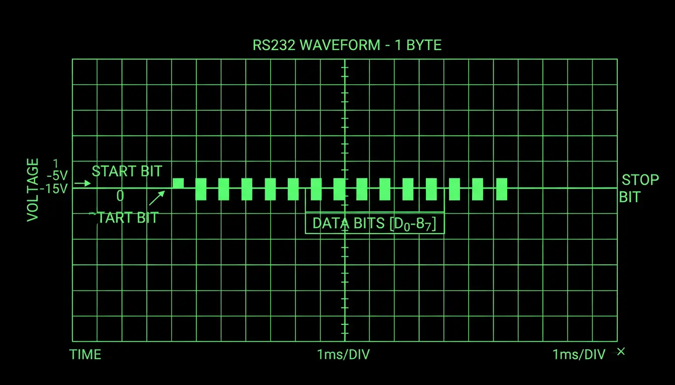
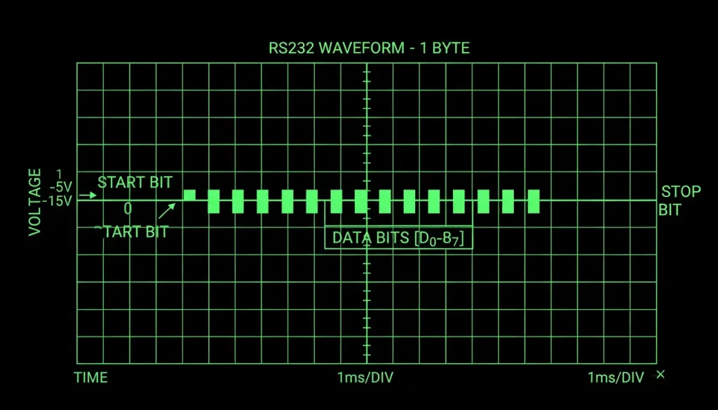
Stage 1: Serial Physical Layer – Turning Voltage Into Bits
Your device sends data over RS232, RS485, or RS422. These are different electrical standards, but they all do the same thing: represent bits as voltage changes.
RS232
RS232 uses voltage relative to ground. A logic 1 is –3V to –15V. A logic 0 is +3V to +15V. The wide voltage swing makes it reliable but limits distance to about 15 meters, as defined by the TIA/EIA‑232 standard .
When your device sends the byte 0x55 (01010101 in binary), the RS232 line toggles between positive and negative voltage 8 times. Each transition is one bit.
RS485
RS485 works with two wires: A and B. When A is more than 200 millivolts higher than B, that’s a logic 1. When B is more than 200 millivolts higher than A, that’s a logic 0. The differential signaling cancels common‑mode noise, allowing distances up to 1,200 meters, as specified in the TIA/EIA‑485 standard .
The way RS485 sends signals helps to get rid of noise. This is because any interference affects both wires in the way so the difference between them stays the same. That is why RS485 can send signals over long distances like hundreds of meters.
The converter has a chip that looks at the changes in voltage, between these two wires. It takes samples at the moments, which are decided by how fast we are sending the signal. Then it uses these samples to figure out the bytes of information that were sent over RS485.
Stage 2: Inside the Converter – From Bytes to Packets
Now the converter has a stream of bytes. They arrive one after another, at whatever speed the device sends (1200 bps to 921600 bps).
The converter’s processor does several things:
1. Buffering
Bytes pile up in a memory buffer while waiting to be sent. If the device sends faster than the network can handle, the buffer fills. If it overflows, data gets lost. Good converters have buffers large enough for their rated speed.
2. Packetization
The converter doesn’t send every byte immediately over Ethernet. That would be inefficient—each tiny packet has 40+ bytes of header overhead. Instead, it waits for one of three things:
- A certain number of bytes accumulate
- A certain time passes
- A special character arrives (if configured)
Then it wraps the bytes in a TCP or UDP packet.
3. Header Addition
A TCP packet header contains:
- Source port (which serial port this came from)
- Destination port (configured in the converter)
- Sequence number (for tracking)
- Checksum (for error detection)
The IP header adds:
- Source IP (the converter’s address)
- Destination IP (your computer’s address)
- Protocol type (TCP or UDP)
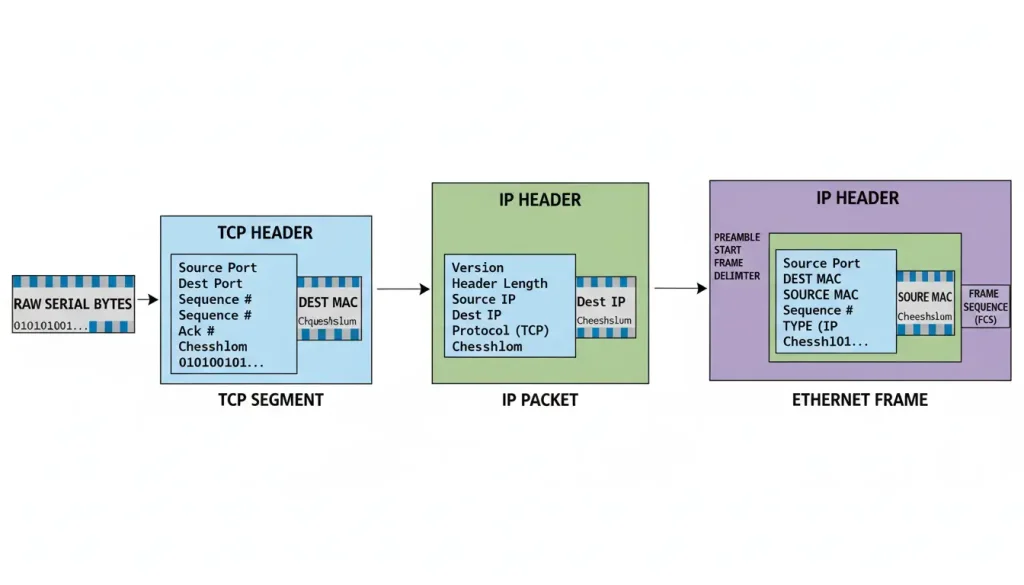
The original serial data becomes the “payload” inside these headers. The network doesn’t care what the data is—it just transports the packet.
Stage 3: Network Transmission – Packets on the Wire
The complete Ethernet frame leaves the converter’s RJ45 jack. It contains:
- Ethernet header (MAC addresses)
- IP header
- TCP/UDP header
- Your serial data
- Ethernet checksum
This frame goes through switches. Maybe routers too until it gets to your computer.
At each stop devices check the headers to figure out where to send it. They do not look at your data. It is just cargo.
Stage 4: Computer Reception – From Packets Back to Bytes
Your computer gets a frame from the network. The network card takes off the Ethernet information. Sends the internet packet to the operating system of your computer.
The operating system of your computer checks the internet packet and the TCP headers. It finds out which port the information is going to. It looks to see if any program is using that port. The operating system is looking for a program that is waiting to receive information on that port.
Two things can happen here:
Option A: Socket Connection
If you wrote a custom program that opens a TCP socket, it receives the data directly. Your program sees the byte stream exactly as the serial device sent it.
python
# Very simplified example
import socket
s = socket.socket(socket.AF_INET, socket.SOCK_STREAM)
s.bind(('0.0.0.0', 4001))
s.listen()
conn, addr = s.accept()
data = conn.recv(100)  # Gets raw serial bytes
Option B: Virtual COM Port
If you’re using old software that only knows COM ports, you need a virtual COM port driver.
This driver (VirCom for Valtoris devices) creates fake COM ports in Windows. When an application opens COM5, the driver intercepts the calls and sends the data over TCP to the converter’s IP and port.
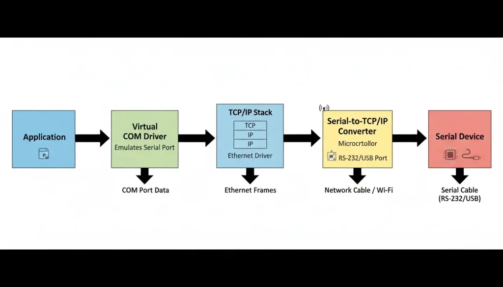
From the application’s perspective, it’s talking to a normal serial port. It doesn’t know the data is going over a network.
The Three Operating Modes – What They Really Mean
You’ll see these options in every converter’s configuration. Here’s what they actually do.
TCP Server
The converter listens on a specific port, waiting for incoming connections.
Think of it as: A phone that’s just sitting there, waiting for someone to call. Once connected, both sides can talk.
Data flow: Computer initiates connection → converter accepts → bidirectional communication.
Use when: Your computer needs to initiate communication, like polling devices on a schedule.
TCP Client
The converter actively connects to a specified IP address and port.
Think of it as: The converter picks up the phone and dials your computer. Once answered, both sides can talk.
Data flow: Converter initiates connection → computer accepts → bidirectional communication.
Use when: The converter needs to push data without being asked, like a remote sensor reporting every hour.
UDP
No connection. The converter sends packets to a destination IP and port without checking if anyone is listening.
Think of it as: Shouting into a room. Maybe someone hears, maybe not. No acknowledgment.
Data flow: One-way, or two-way if both sides shout at each other.
Use when: You don’t need guaranteed delivery, or when multiple devices need the same data (broadcast).
Virtual COM Ports – How They Fool Windows
This idea is worth exploring because it seems smart.
Windows has a way for serial ports to work. Hardware makers create drivers that tell Windows “I have a COM port, at this address. This is how you can read and write to it.”
Virtual COM port software works in a way. Of connecting to physical hardware it connects to the network.
When you install VirCom:
- It registers with Windows as a serial port driver
- It creates new COM ports (COM5, COM6, etc.) in the registry
- When an application opens COM5, VirCom gets the call
- It opens a TCP connection to the converter’s IP and port
- Data from the application goes out the TCP connection
- Data from the converter comes back and is fed to the application
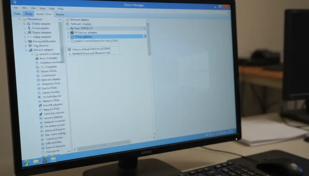
The application has no idea. It just sees a normal COM port with a familiar name.
The Critical Importance of Serial Settings
Converters are transparent pipes, but the pipe has to match the device on both ends.
| Setting | What It Actually Means |
|---|---|
| Baud rate | How many signal changes per second. 9600 baud = 9600 symbols/sec. For standard serial, one symbol = one bit, so 9600 baud = 9600 bits/sec. |
| Data bits | How many bits make up one character. Usually 8 (for binary data) or 7 (for old ASCII). |
| Parity | Error detection. Adds an extra bit to make the total number of 1s even (even parity) or odd (odd parity). |
| Stop bits | Pause between characters. Usually 1, sometimes 2 for slow mechanical devices. |
If the settings do not match exactly the converter will still send data. It will be incorrect. A character sent as 0x41 might be received as 0xC2 or not received all.
Why can’t the converter auto-detect this? Because serial has no handshake at this level. It’s like two people speaking different languages at the same volume. They hear each other, but nothing makes sense.
Industrial vs. Consumer – What’s Different Inside
Consumer-grade converters and industrial ones look similar from the outside. Inside, they’re different.
Temperature tolerance
Industrial: -40°C to 85°C
Consumer: 0°C to 40°C
The thing that sets them apart is the components they use. Industrial grade chips are put through tests. They get ratings, for working in really hot or really cold temperatures. The electrolytic capacitors are made to last a time even when it is very hot.
Isolation
Industrial converters often have optocouplers between the serial side and the network side. These transmit signals using light, with no electrical connection.
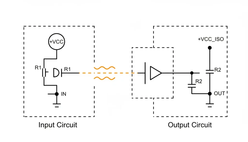
This prevents ground loops. If your serial device is at a different ground potential than your network equipment, current can flow through the signal wires. Isolation blocks that current.
Power supply
Consumer: 5V USB (assumes clean power from a phone charger)
Industrial: 9-24V DC (accepts the noisy power found in factories)
Enclosure
Plastic is fine in an office. In a factory, metal acts as a heatsink and shields against electromagnetic interference from motors and drives.
What About Modbus?
If your serial device uses Modbus RTU, many converters can act as Modbus gateways.
The converter is waiting for Modbus TCP connections on port 502. This is the port that Modbus TCP uses.
When it gets a request the converter changes it to Modbus RTU. Then it sends the request out of the port.
When the converter gets a response back it changes the response back to Modbus TCP. The converter then sends the response, over the network to the Modbus TCP connection. The converter is using Modbus TCP to communicate over the network.
This is different from transparent mode. The converter actually understands the protocol and can do things like:
- Aggregate multiple serial devices behind one IP
- Cache register values
- Handle multiple TCP clients simultaneously
A Complete Walkthrough: One Byte’s Journey
Let’s trace a single byte from a temperature sensor to a monitoring application.
1. Sensor side
The sensor measures 22.5°C. Its processor formats this as a Modbus response: 0x01 0x03 0x02 0x00 0xE1 (simplified). It sends these bytes out its RS485 port at 9600 baud.
2. On the wire
Voltage difference appears between A and B wires. First bit: A higher than B. Second bit: B higher than A. Eight bits form the first byte.
3. Converter input
The converter’s RS485 chip detects the voltage differences, samples at the correct times (9600 times per second), and reconstructs the bytes. They go into a buffer.
4. Packetization
The converter waits for a while to see if it gets more bytes. It does this for a time, which is called the packet timeout. When it does not get any bytes it puts all the bytes it got so far into a TCP packet. The TCP packet goes to your computer. The destination port, for the TCP packet is 4001.
5. Network travel
The packet goes through switches. Each switch looks at the destination MAC and forwards it toward your computer.
6. Computer arrival
Your network card receives the packet. The OS sees it’s addressed to port 4001 and checks if any program is listening.
7. Application delivery
Your monitoring software opened a TCP socket on port 4001 earlier. The OS delivers the packet data to that socket. Your software parses the Modbus response and displays 22.5°C.
Total time: milliseconds. The sensor doesn’t know there was a network in between. Your software doesn’t know the data came over RS485.
Common Confusions
“Does the converter change my data?”
No. It is completely transparent. The bytes that go into one end of the converter are the bytes that come out the other end. The converter just. Removes network headers but it does not change the payload. The payload remains the same it is untouched, by the converter.
“Do I need a virtual COM port?”
Only if your software expects a COM port. If you’re writing your own software or using a modern SCADA system that supports TCP sockets, you don’t need it.
“Why do I have to set baud rate if it’s transparent?”
The converter needs to know the speed of the line to work properly. It cannot figure this out on its own. For example when the serial line is set to 9600 baud the converter has to take a sample every 104 microseconds. On the hand when the serial line is set to 115200 baud the converter must take a sample every 8.68 microseconds. If the converter uses the speed it will get the wrong data, from the serial line. The serial line speed is very important for the converter to get the data.
“Can I connect multiple devices to one converter?”
Yes, with multi-port models. Each port is independent. They can be different baud rates, different modes, even different protocols.
What to Look For in a Converter
If you’re shopping, these specifications matter:
| Spec | What It Means |
|---|---|
| Operating temperature | -40°C to 85°C for industrial |
| Isolation | 1500V or 3000V for ground loops |
| Power input | 9-24V DC for industrial panels |
| Mounting | DIN rail for control cabinets |
| Surge protection | 2KV on Ethernet for reliability |
| Buffer size | Large enough for your data rate |
Valtoris converters (1CH-RS232/485/422-ETH and multi-port siblings) hit these specs. They’re built for where you actually put them, not for a desk.
Summary
Converting serial to Ethernet is a straightforward process:
- Serial device sends bytes as voltage changes
- Converter captures bytes, wraps them in network packets
- Network delivers packets to your computer
- Your software (or virtual COM driver) unpacks them
The converter is like a pipe. It does not care about the data. It just moves it from one place to another.
The magic happens in the layers of protocols. They work together to make Ethernet talk, to each other.