
Remote Modbus Polling with Tatsoft FrameworX & Valtoris Gateways
A comprehensive, end-to-end engineering guide to creating a transparent TCP/IP tunnel, connecting remote field devices directly to FrameworX’s runtime engine.
This guide shows how to configure a Valtoris Gateway to act as a transparent TCP/IP bridge, allowing Tatsoft FrameworX to bypass cellular NAT barriers and directly poll remote Modbus RTU/TCP edge devices.
Configuration workflow
- Verify and bind a static WAN address on the Valtoris Gateway.
- Configure firewall Port Forwarding to route external Modbus traffic (Port 502) to the internal PLC.
- Test the connectivity using a standard Windows Ping diagnostic.
- Initialize the Modbus TCP Channel and Remote Node in FrameworX Designer.
- Map device Points (Tags) and launch the Runtime to begin demand-driven polling.
1. Valtoris Gateway: Network & Interface Preparation
To enable Tatsoft FrameworX to query field devices reliably, we must establish a stable WAN connection and configure the router’s interfaces.
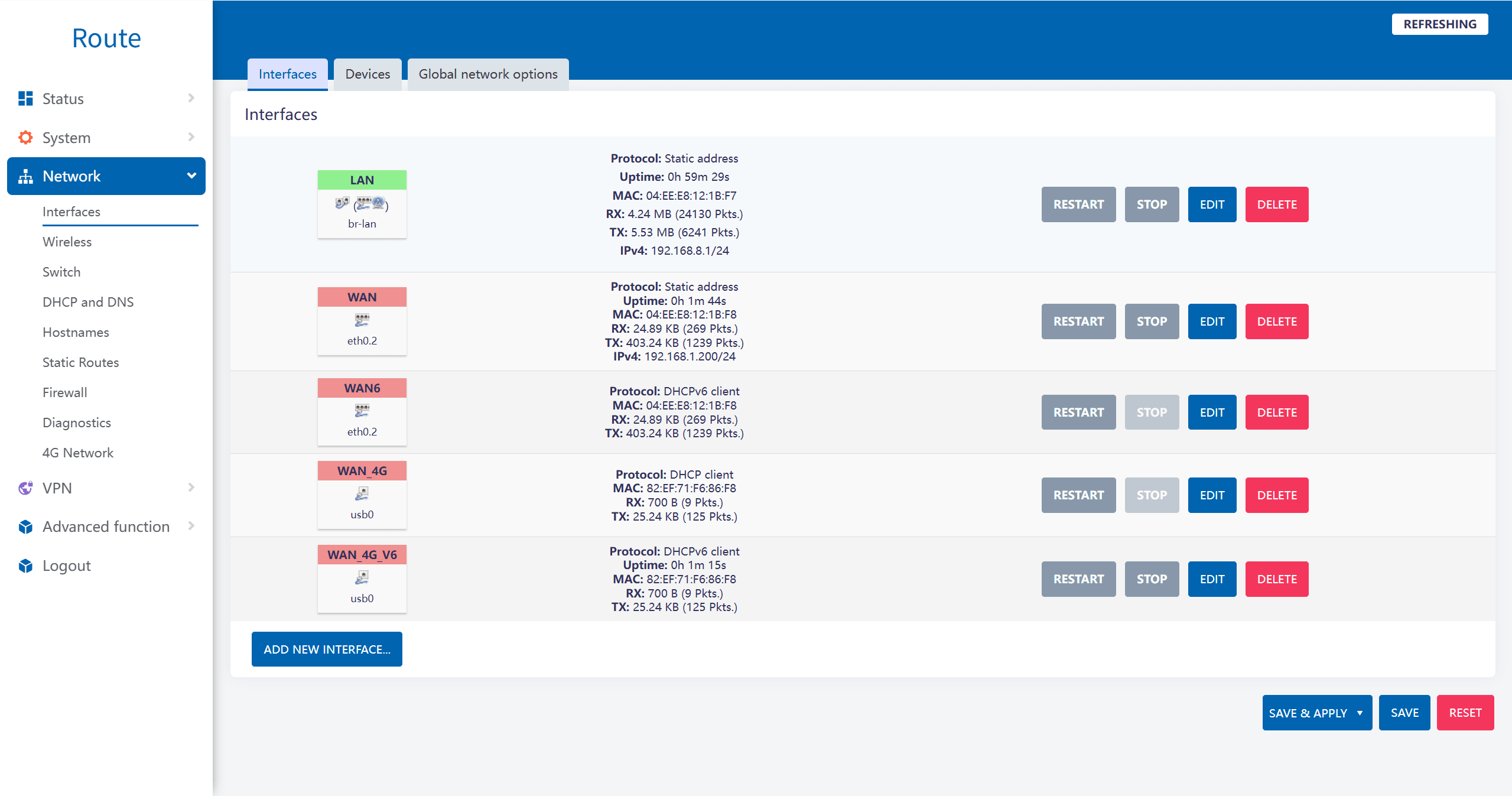
Step 1.1: Verify Interface Status
Navigate to Network -> Interfaces in the Valtoris Web GUI. Here you can overview your active LAN, WAN, and 4G connections.
Step 1.2: Bind a Static WAN Address
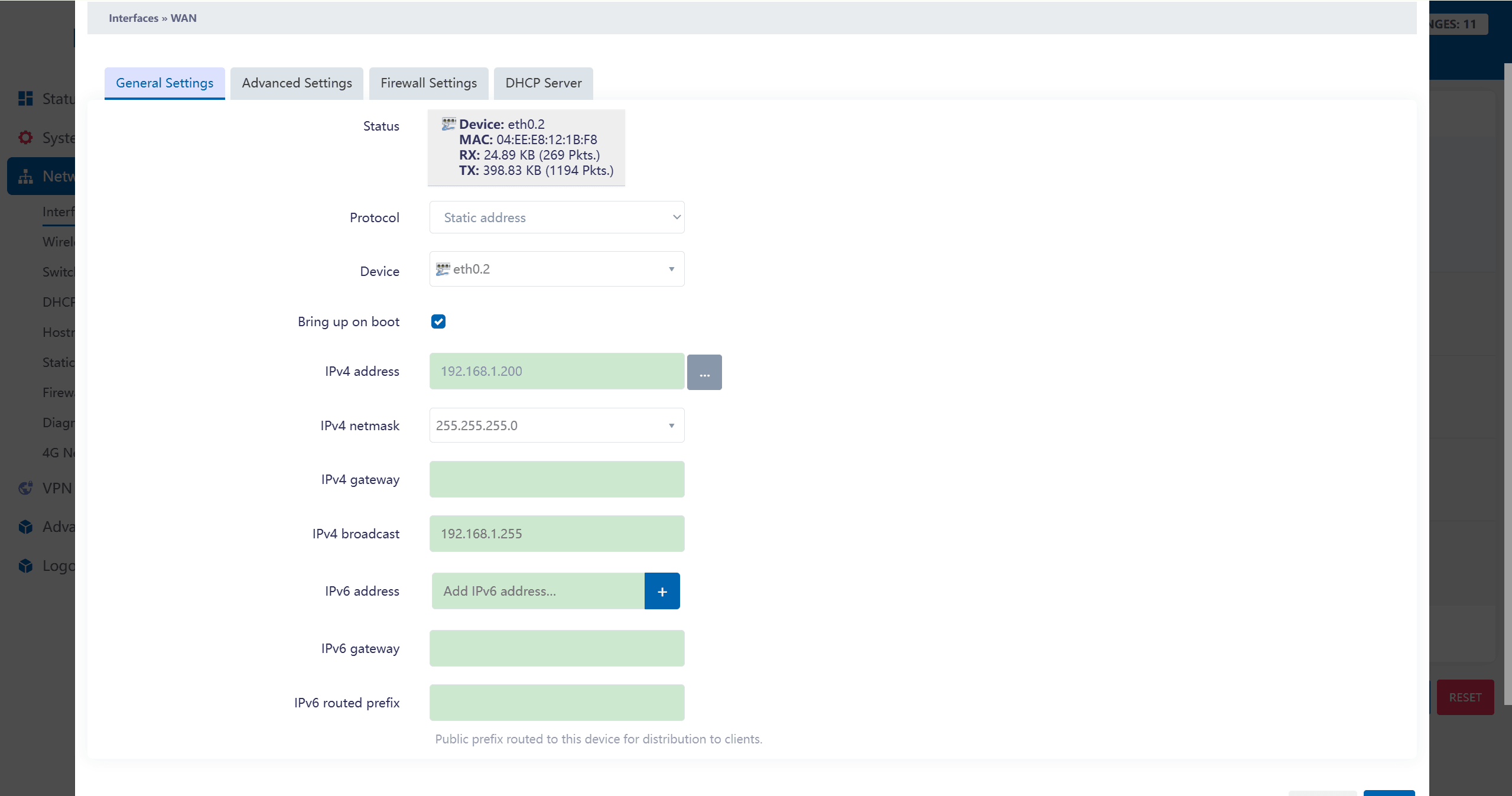
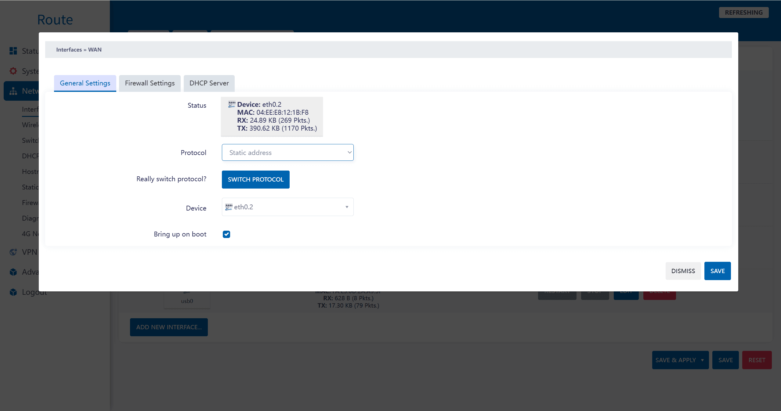
Click EDIT on your active WAN interface. To ensure SCADA always knows where to poll, switch the Protocol to Static address and assign a fixed IPv4 address (e.g., 192.168.1.200).
2. Firewall & Port Forwarding Setup
Next, we must instruct the gateway to allow external SCADA requests and route them directly to the Modbus device on the local network.
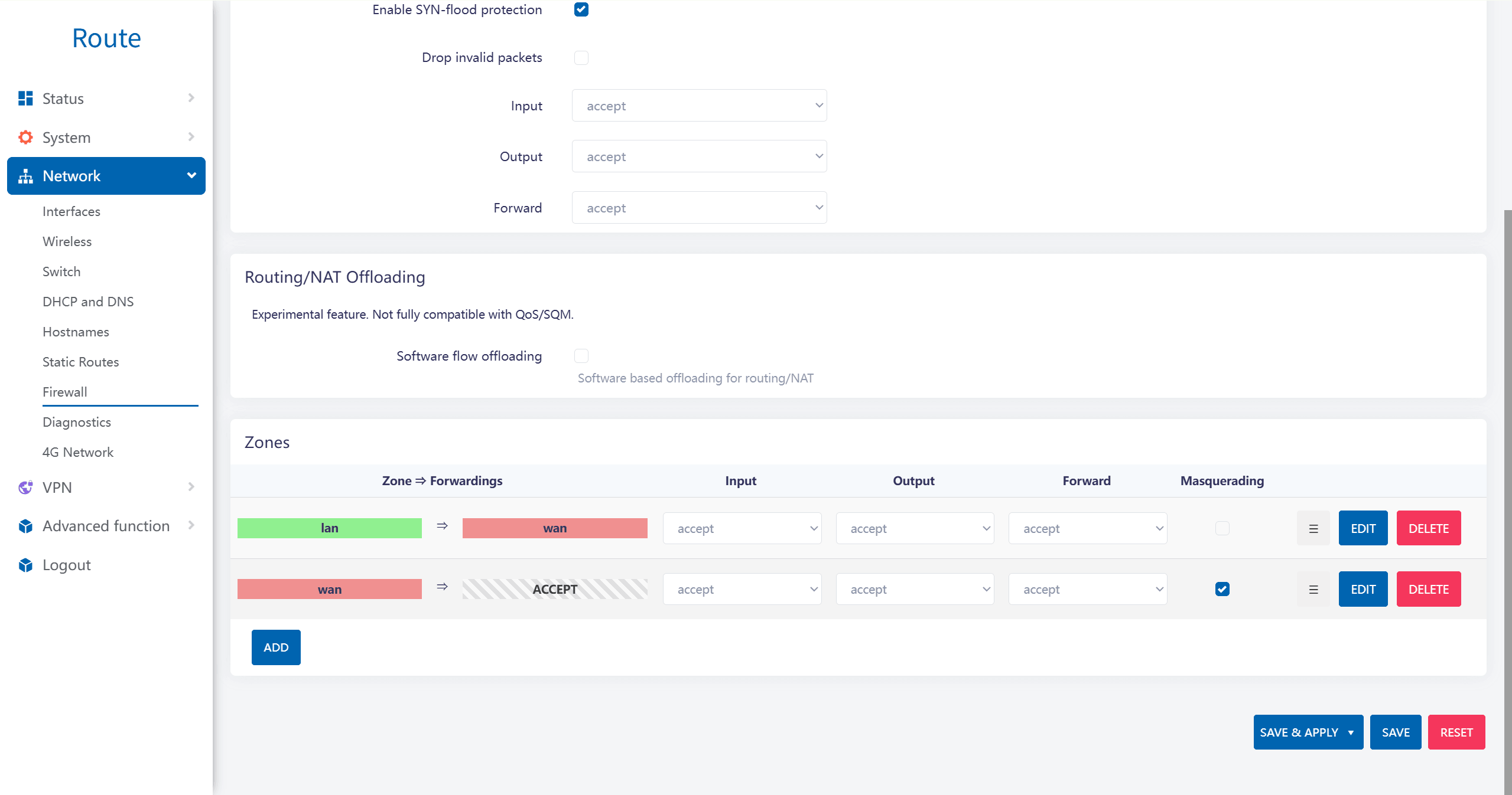
Step 2.1: Allow WAN Zone Traffic
Navigate to Network -> Firewall. Ensure that the wan zone’s Input, Output, and Forward settings are set to accept so traffic is not dropped.
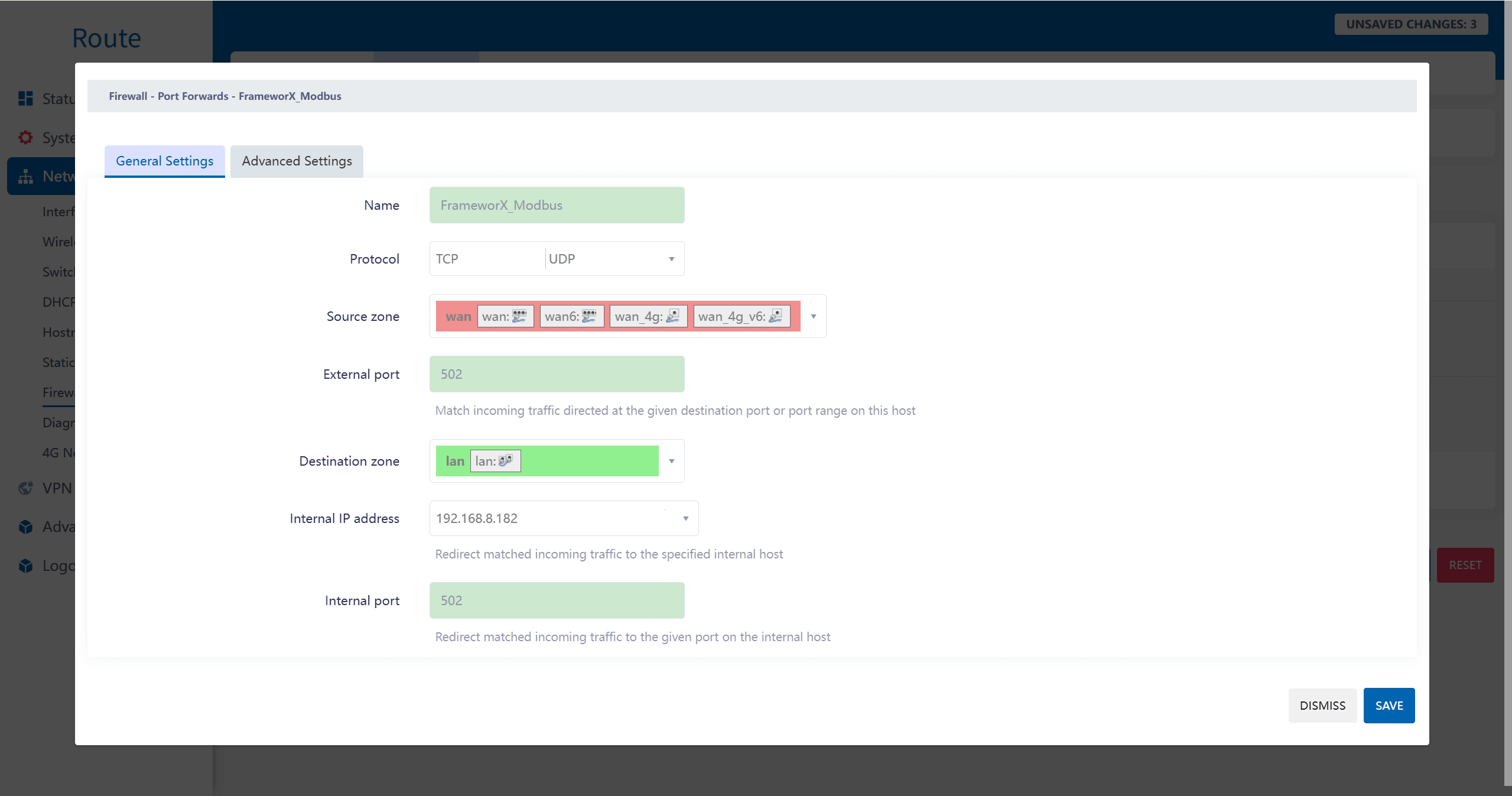
Step 2.2: Configure Port Forwarding Rule
Go to the Port Forwards tab and create a new rule for FrameworX:
- External Port: 502 (Standard Modbus Port expected by FrameworX)
- Internal IP Address: 192.168.8.182 (The local IP of your field PLC or Modbus device)
- Internal Port: 502
3. Pre-Flight Diagnostic Check
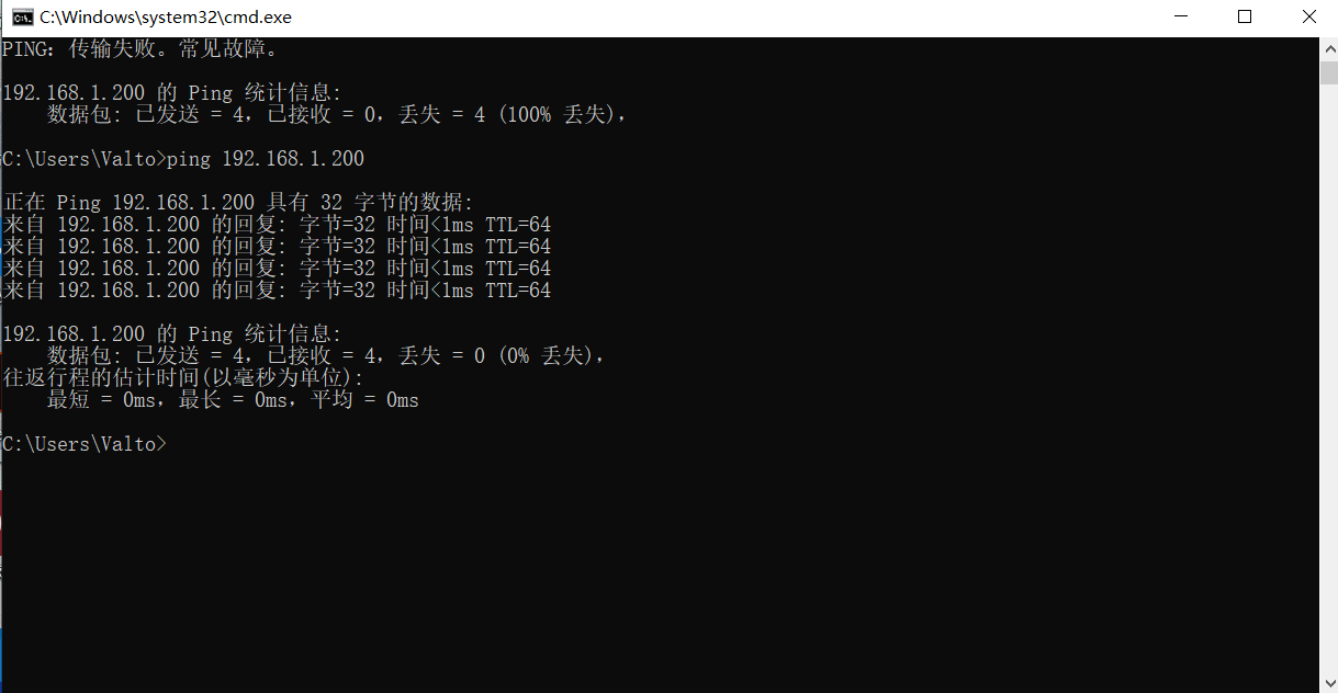
Before launching your IIoT platform, it is highly recommended to perform a standard Windows ping test to verify the hardware tunnel is accessible.
4. Tatsoft FrameworX: Channel & Tag Binding
With the Valtoris Gateway acting as a transparent bridge, we configure the FrameworX Designer.
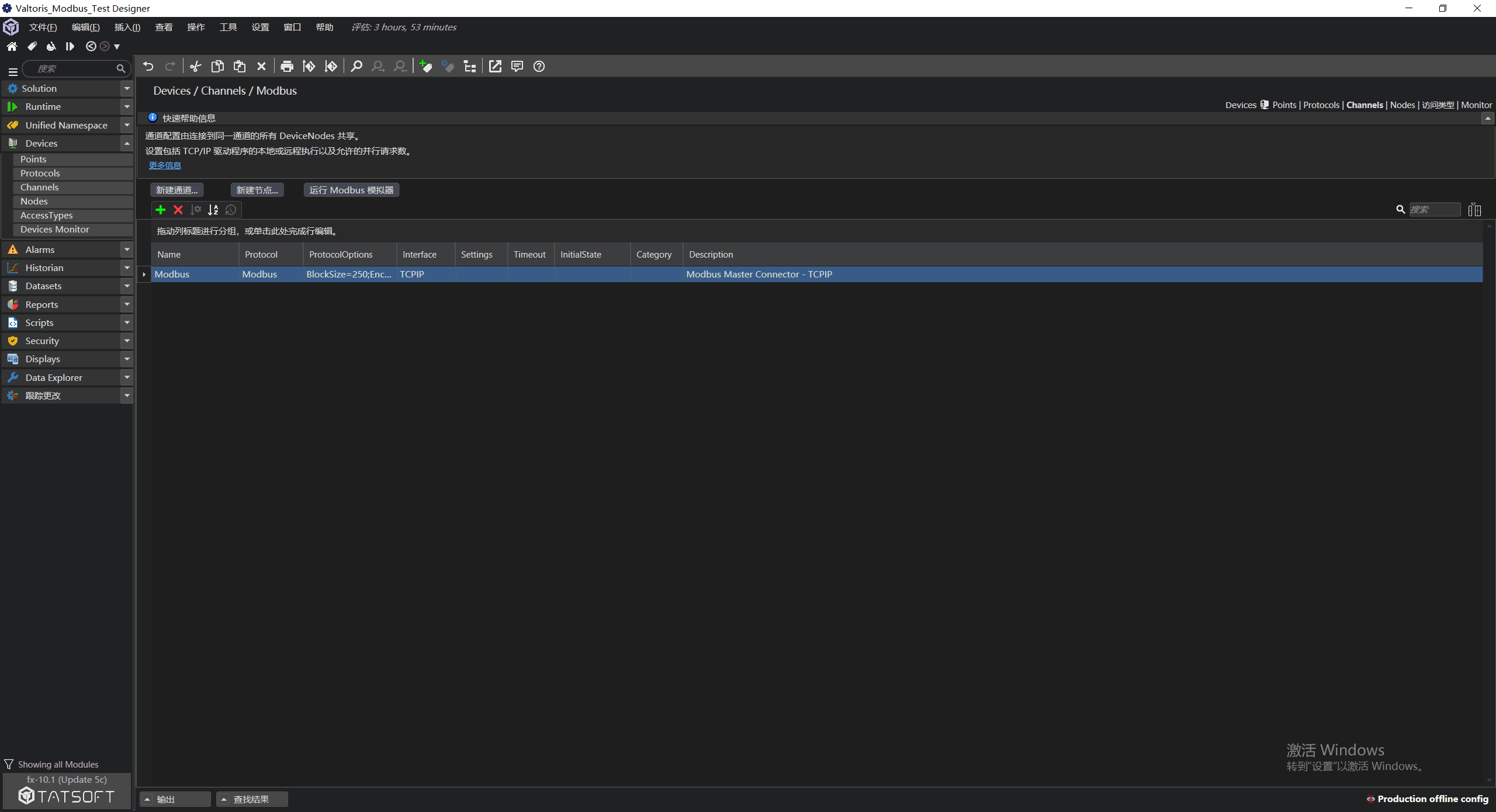
Step 4.1: Initialize Modbus TCP Channel
Navigate to Devices -> Channels. Create a channel specifying Protocol as Modbus and Interface as TCPIP.
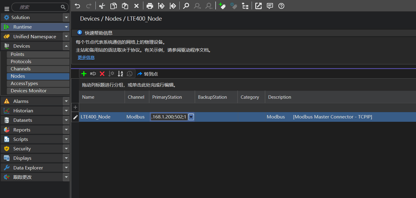
Step 4.2: Define the Remote Node
Go to Devices -> Nodes and create a node (LTE400_Node). In PrimaryStation, enter the Gateway’s IP and Port: 192.168.1.200;502;1.
Step 4.3: Map Device Points (Tags)
Go to Devices -> Points and create a TagName (Temp_Value). Assign it to your Node and set the Address to 40001.
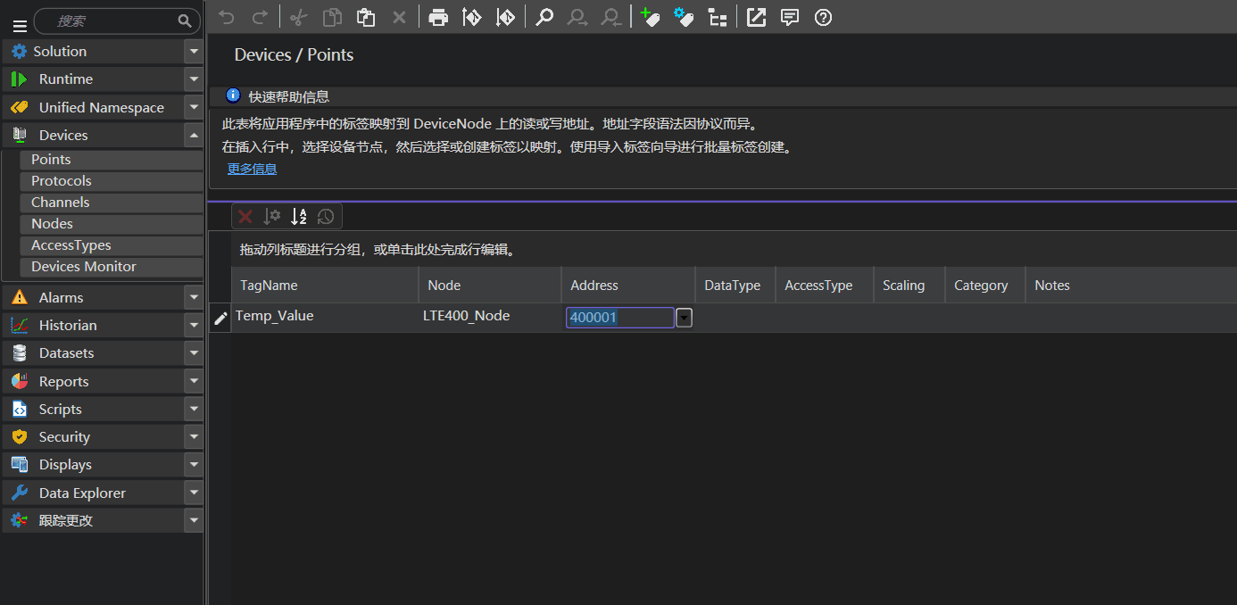
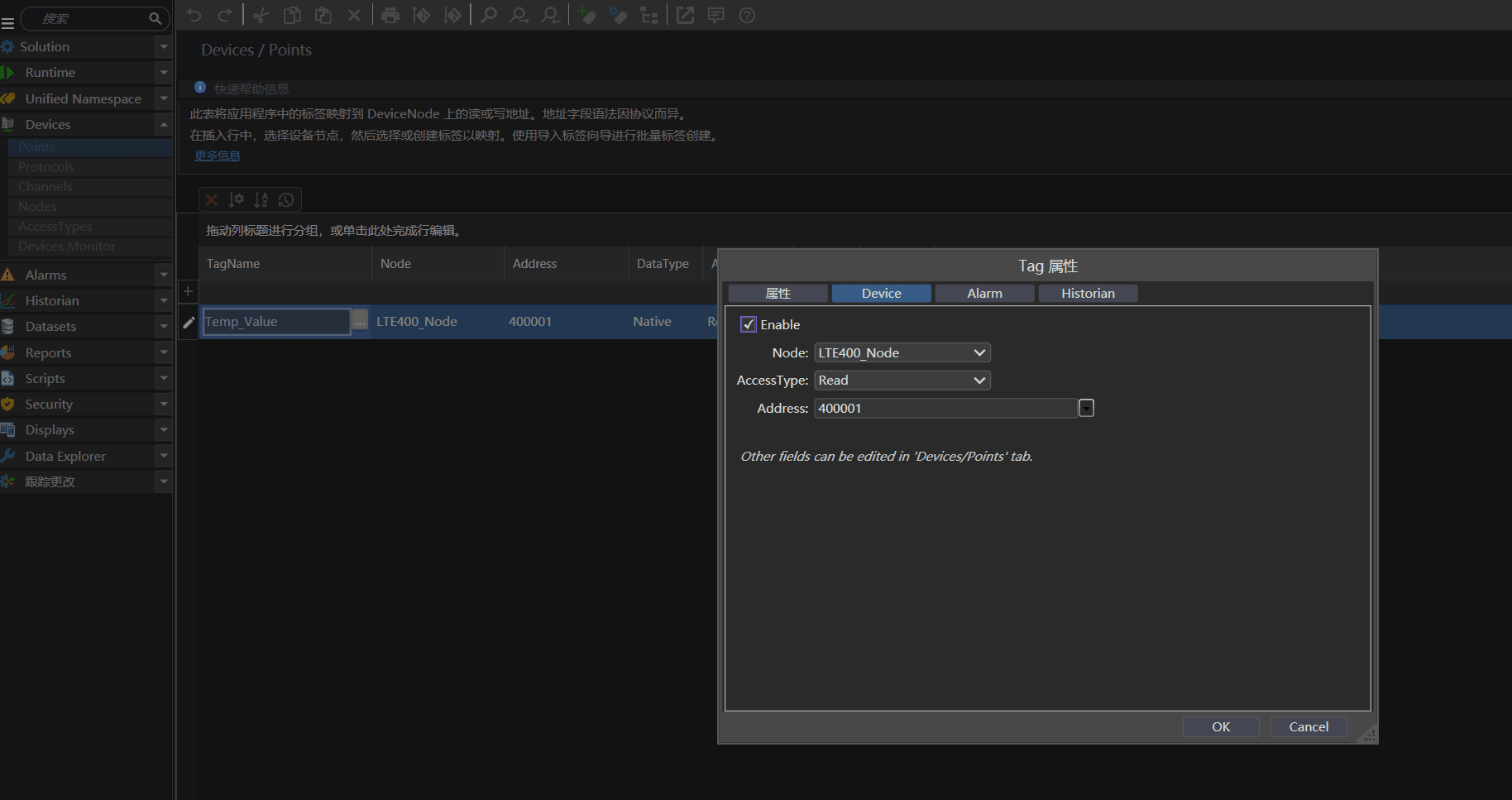
Crucial Step: Double-click the cell to open Tag Properties and ensure the Enable checkbox is ticked, otherwise data will not be polled.
5. Runtime Execution & Live Monitoring
Tatsoft FrameworX utilizes a Demand-Driven Polling Engine. Data is only requested when actively required by an interface.
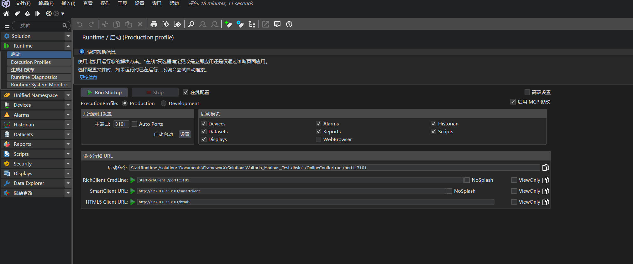
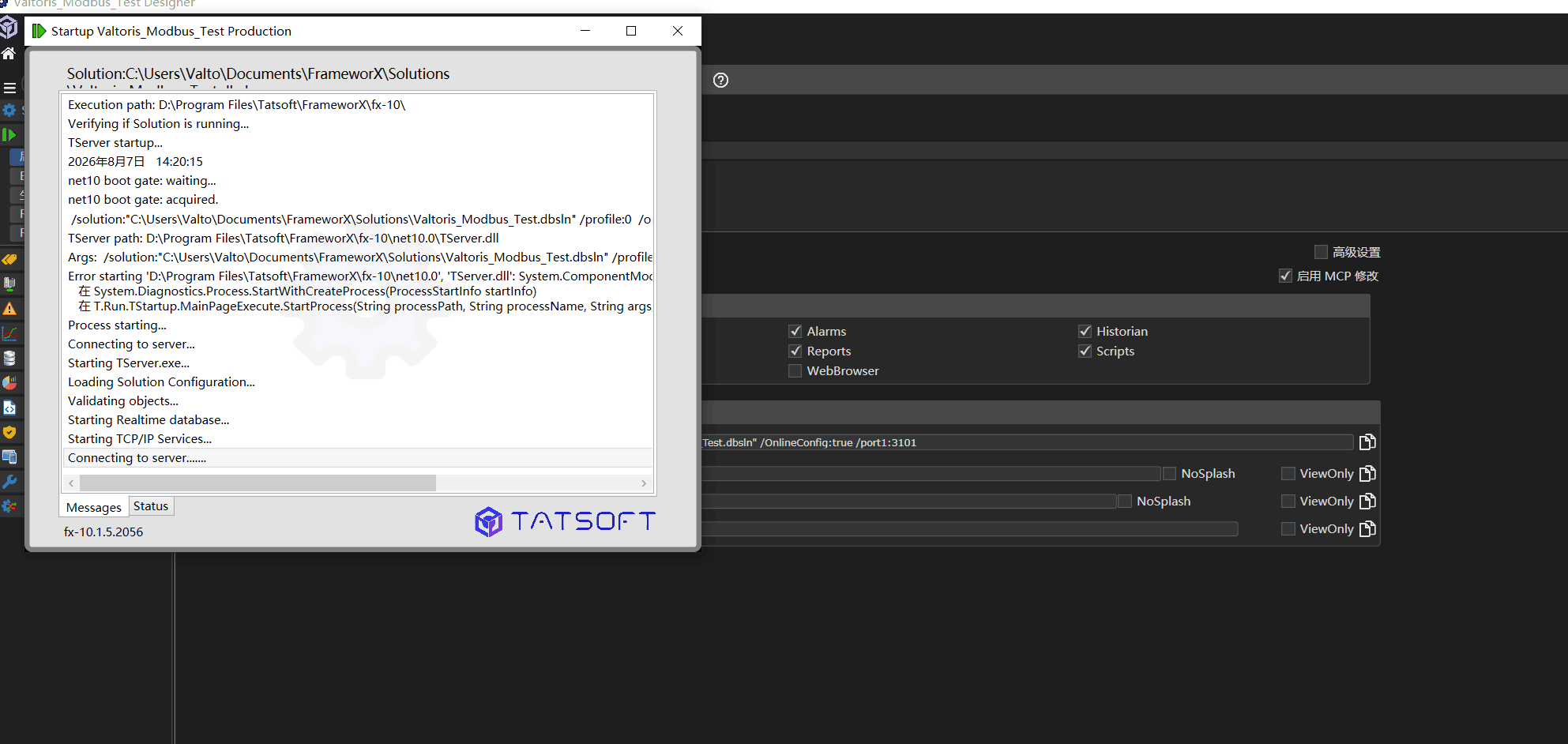
Step 5.1: Configure & Launch Runtime
Navigate to Runtime -> Startup. Ensure your Devices, Displays, Alarms, and Historian modules are selected for the Production profile, then click Run Startup.
Step 5.2: HMI Display Binding (Success!)
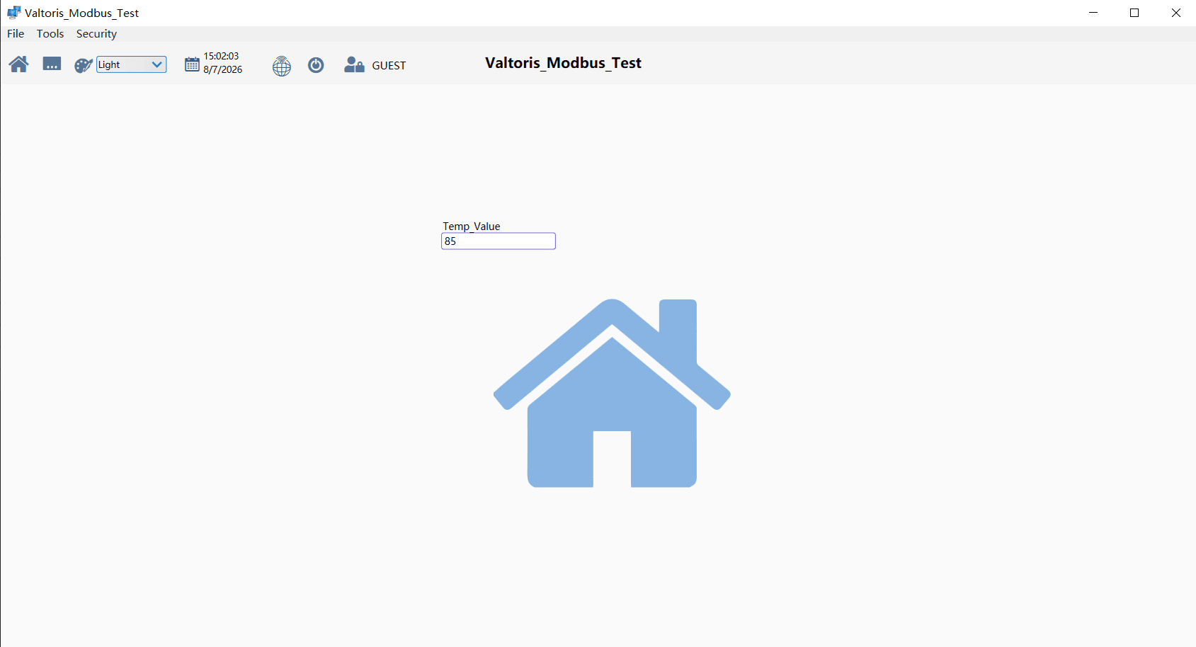
By dragging the Temp_Value tag onto a live Display, the engine is forced to poll. The data will seamlessly traverse the Valtoris Gateway.
Deploying Enterprise IIoT Networks?
Need reliable hardware to bridge the gap between your remote field assets and Tatsoft FrameworX? Connect with our OT networking engineers to find the right industrial cellular router or serial device server for your topology.
