
Remote Modbus Polling with Fernhill SCADA & Valtoris Gateways
A step-by-step engineering guide to creating a transparent, low-latency TCP/IP tunnel connecting remote field devices directly to Fernhill SCADA’s runtime.
1. Valtoris Gateway: 4G Network & Port Forwarding
To allow Fernhill SCADA to poll our remote devices over a cellular network, we first need to verify the connection and expose the local Modbus port via Port Forwarding.
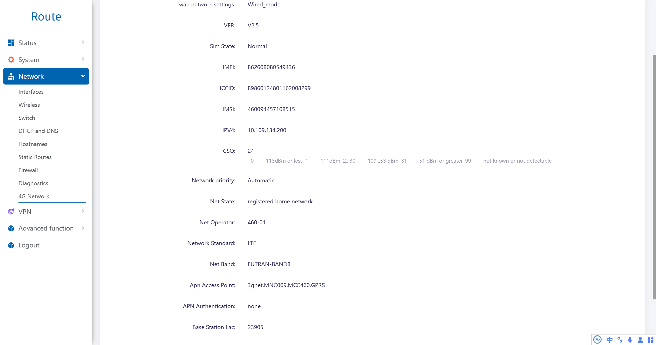
Step 1.1: Verify 4G Cellular Connection
Navigate to Network -> 4G Network in the Valtoris Web GUI. Ensure the WAN mode is set to 4G Mode.
Step 1.2: Configure Port Forwarding
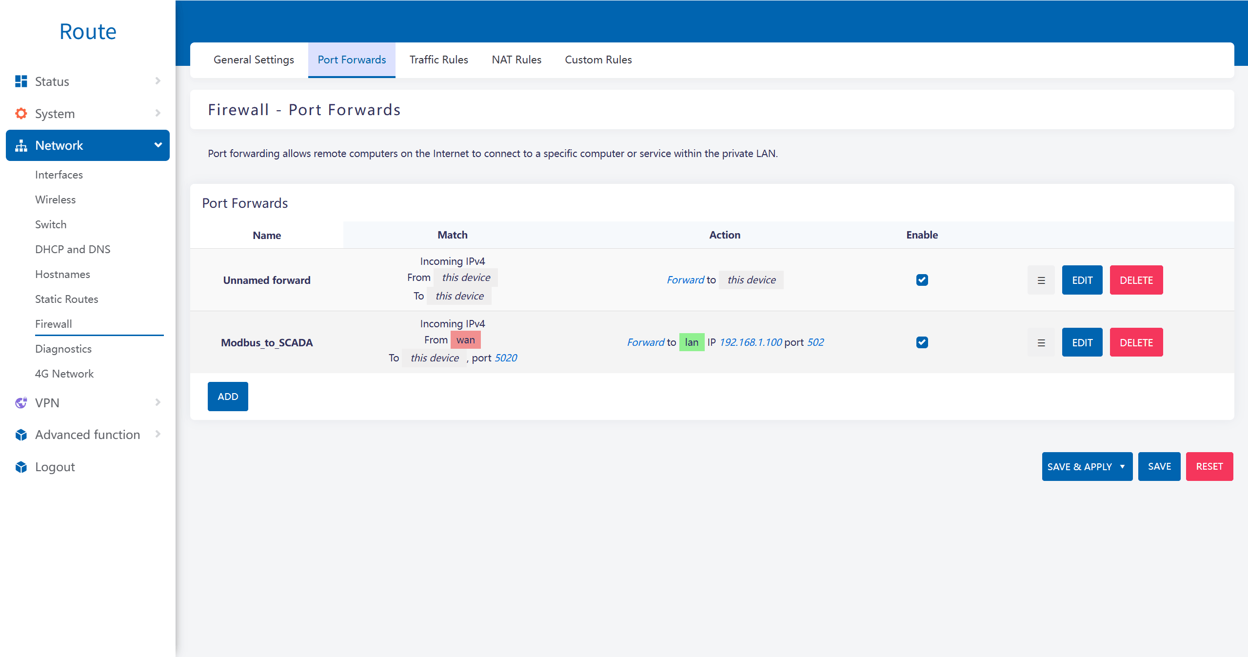
Navigate to Network -> Firewall -> Port Forwards. We will create a rule to map incoming SCADA traffic to our internal PLC.
- External Port: 5020 (The port Fernhill SCADA will connect to)
- Internal IP Address: 192.168.1.100 (The local IP of your Modbus device)
- Internal Port: 502 (Standard Modbus TCP port)
Status Check
With Port Forwarding saved and applied, the Valtoris Gateway is now acting as a transparent TCP server. Fernhill SCADA can now reach the internal Modbus device by pointing to the Gateway’s WAN IP on Port 5020.
2. Fernhill SCADA: Data Reception & Configuration
With the hardware tunnel established, we configure the software side. Please ensure you have downloaded and installed the Fernhill SCADA Windows Developer package from their official website.
Step 2.1: Create a Working Folder
It is good practice to create a working folder for related tags.
- Connect the Fernhill SCADA Configuration Tool to a Fernhill SCADA Server.
- Right-click the database root folder and select Add new Folder.
- Change the name to ‘Valtoris’ and press RETURN.
Step 2.2: Create a Modbus TCP Channel Tag
- Right-click the folder you created in step 2.1.
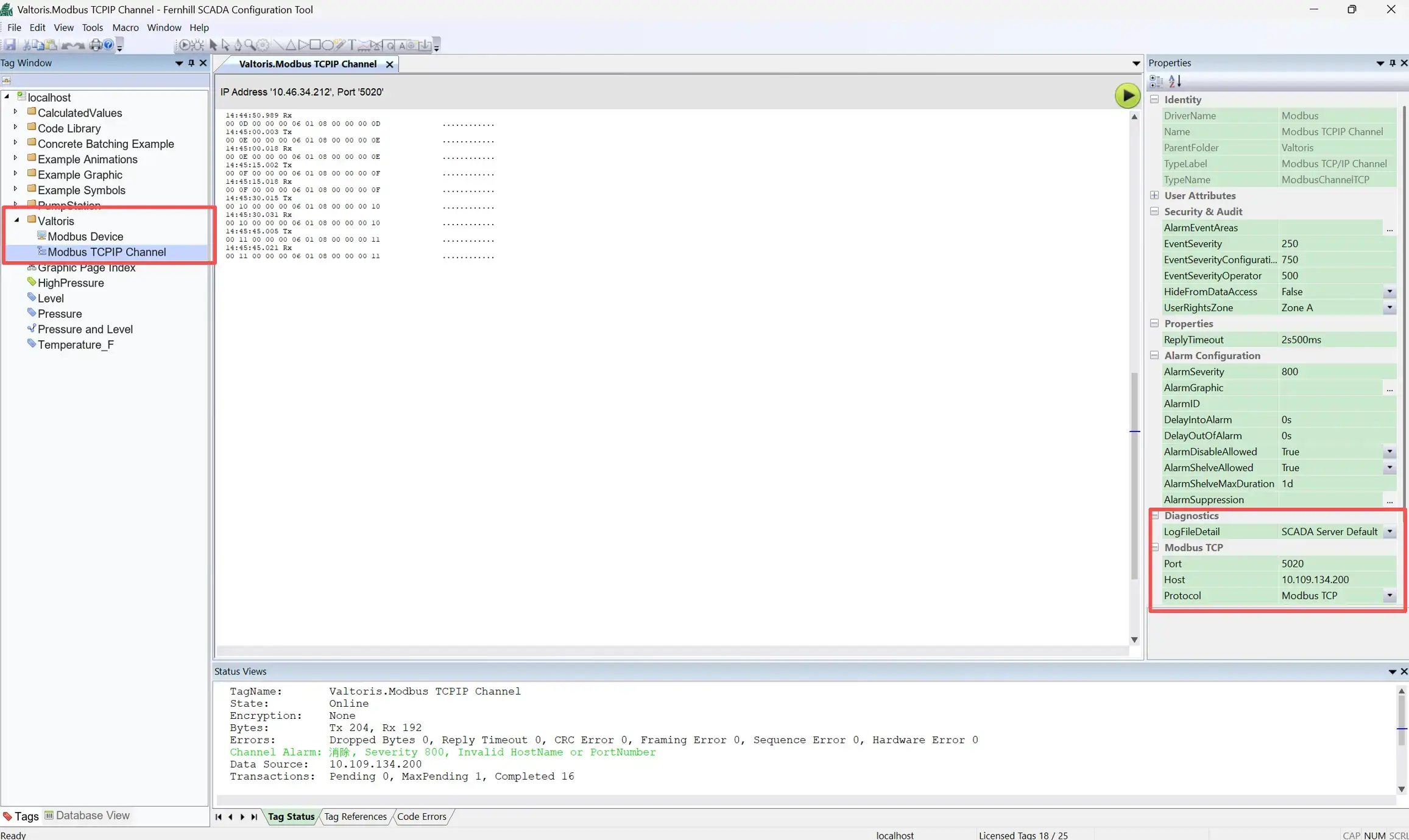
- Select Add New Tag -> Modbus -> Modbus TCP/IP Channel.
- Change the name to ‘Channel’ and press RETURN.
- In the Properties Window: Set Port to 5020 (matching the External Port created in Step 1.2).
- Set Host to the IP Address of the Valtoris Gateway.
- In the Tag Status Window, check there is a successful connection.
Step 2.3: Create a Modbus Device Tag
- Right-click the folder you created in step 2.1.
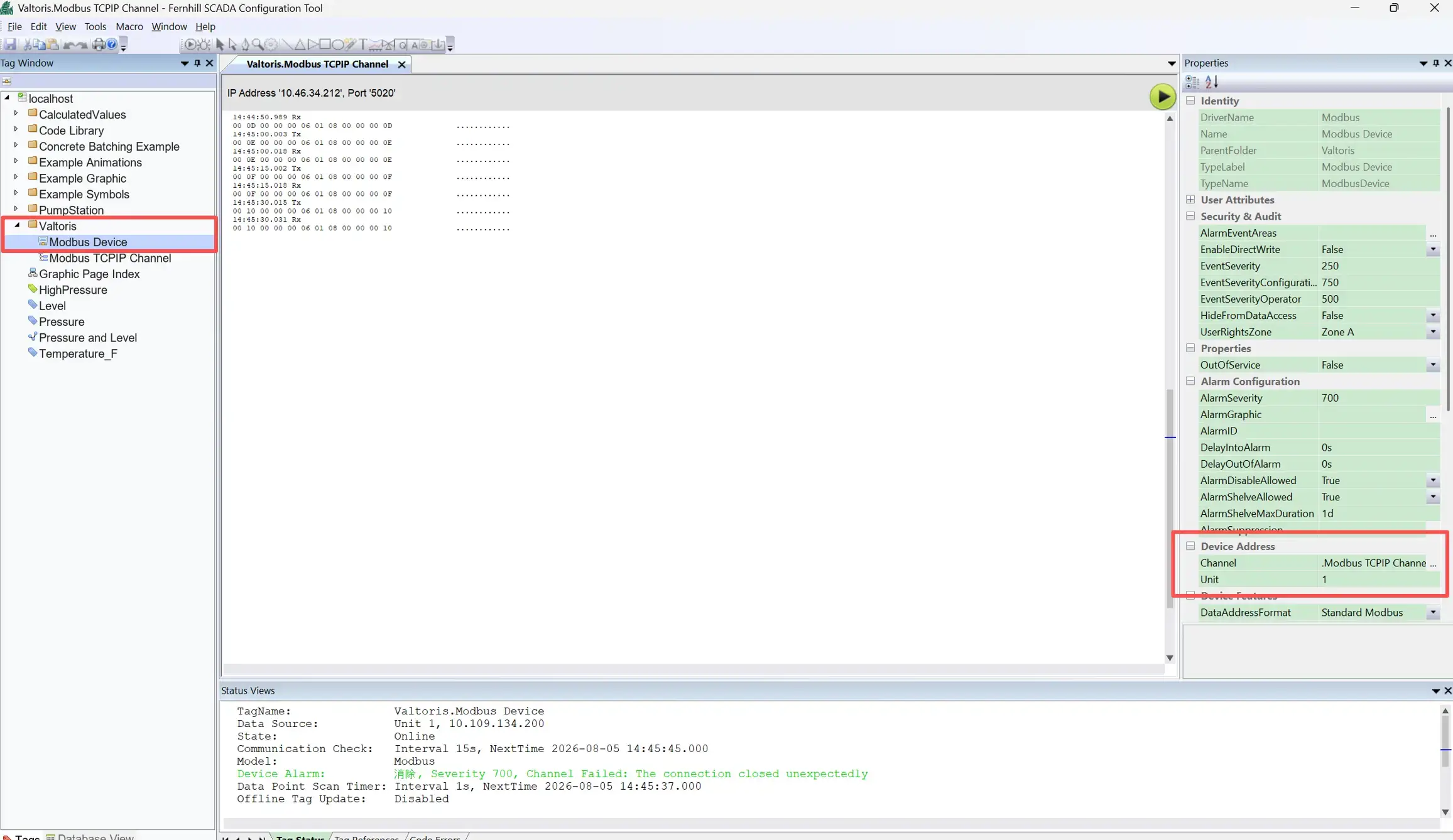
- Select Add New Tag -> Modbus -> Modbus Device.
- Press RETURN to accept the default name.
- In the Properties Window: Click the Browse “…” button of the Channel property.
- Select the Channel Tag you created in step 2.2. Click OK.
- Use the Tag Status Window to confirm the Modbus Device tag is working as expected.
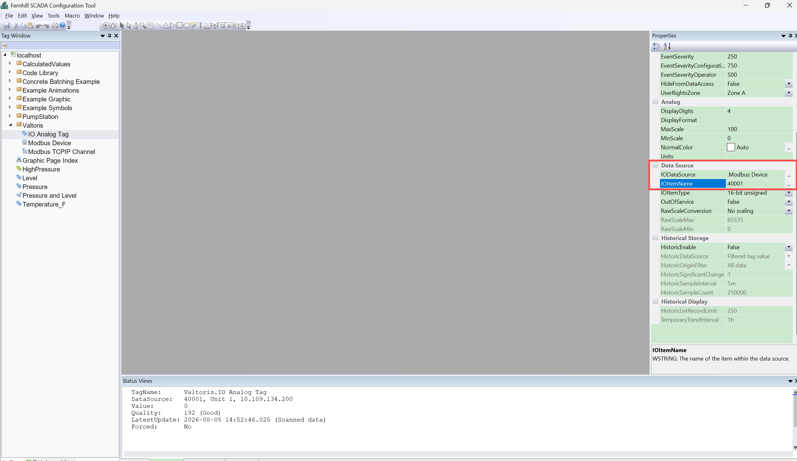
Step 2.4: Create an Analog Data Point Tag
- Right-click the folder you created in step 2.1.
- Select Add New Tag -> Core -> I/O Analog Tag.
- Press RETURN to accept the default name.
- In the Properties Window: Click the Browse “…” button of the IODataSource property.
- Select the Modbus Device Tag you created in step 2.3. Click OK.
- In the IOItemName property, enter the Modbus Register Address. For example: 40001.
- Use the Tag Status Window to confirm the Analog Data Point Tag is working as expected.
⚠️ Common Troubleshooting
1. 4G Network Connection Fails
Check the blue 4G lamp on the front panel of the VT-LTE400. If the indicator is steady on, the router is still dialing. If the indicator is blinking, the dial is successful. Ensure your SIM card is inserted correctly while powered off.
2. SCADA Cannot Reach the Remote Device
If Fernhill shows a timeout, the network may not be bidirectional. From the Valtoris Web GUI, go to Network -> Firewall. Configure the firewall forwarding rules (Input, Output, Forward) to ACCEPT so that they allow external traffic to pass through the tunnel.
Deploying Remote SCADA Networks?
Need reliable hardware to bridge the gap between your remote field assets and Fernhill SCADA? Connect with our OT networking engineers to find the right industrial router for your topology.
