
SCADA Missing Pulses? The Modbus Pulse Counter Solution
A central SCADA system should be able to accept a high speed pulse output flow meter or electricity meter without much difficulty. Automation engineers, however, often get frustrated with an anomaly where the physical meter reading at the remote site is always higher than the total in the central SCADA database.
If your system is losing data, it is seldom a software bug or a broken wire. This is a basic conflict between the physics of a physical pulse and the architecture of industrial networking.
- Symptom: SCADA accumulated totals are lower than the physical dial. Random pulses are permanently dropped.
- Status Codes: Data Mismatch or Missing Pulses.
- Root Cause: Asynchronous polling. SCADA polling intervals (e.g., 1000ms) are too slow to capture brief mechanical pulse widths (e.g., 50ms).
| Threat 1: Missing Pulses | The “Blink” Effect: Your flow meter generates a pulse that lasts only 50ms. Your SCADA asks for data every 1000ms. If the pulse happens while SCADA isn’t looking, the data is completely lost. |
|---|---|
| Threat 2: Phantom Pulses | Mechanical Jitter: When physical contacts close, they microscopically bounce. SCADA might misread a single 10-gallon pulse as a rapid burst of 5 fake spikes. |
The Root Cause: The SCADA Polling Trap & Contact Bounce
The fundamental cause of missed pulses is the physical limitations of network sampling, which are described by similar rules to the Nyquist–Shannon sampling theorem. You cannot record a physical event unless your network is “looking” at it at the time it happens.
A high-speed spinning flow meter produces fast, transient pulses. For example, a standard dry contact pulse might only be “closed” (active) for 50 milliseconds, then open again.
Standard SCADA systems communicate using Modbus TCP by “polling” the remote node. A typical Modbus poll rate on a LAN or Cellular network is 1000 milliseconds (1 second). If the SCADA asks the gateway “Is the contact closed?” every 1000ms, but the physical pulse only lasts 50ms, the SCADA is statistically blind to the vast majority of the fluid flowing through the pipe. It only picks up random pulses that happen to coincide with the precise millisecond the network query arrives.
The Secondary Threat: Phantom Pulses (Contact Bounce)
While the network misses pulses, mechanical issues often create false ones. When a physical flow meter relay closes, the metal contacts microscopically “bounce” against each other. This mechanical jitter can cause a single 10-gallon pulse to be misread as 10 rapid electrical spikes, severely distorting data. A robust solution must solve both the network latency and the physical noise.
Why “Just Polling Faster” Will Crash Your Network
It might seem logical to simply reduce the Modbus polling interval from 1000ms down to 10ms to “catch” the fast pulses. Do not do this. Forcing a SCADA server to bombard a remote node with TCP requests every 10 milliseconds will cause severe network congestion. The remote gateway’s CPU will max out, Modbus timeout errors will cascade across your HMI, and your entire automation network will crash.
Evaluating Your Options: 3 Realistic Paths to Fix Pulse Loss
To fix the data loss permanently, you must decouple the physical speed of the water meter from the network speed of your SCADA system. In industrial automation, engineers typically evaluate three architectures depending on budget and site layout:
3 Critical Features to Look for in a Modbus Pulse Counter
Some Ethernet I/O modules do not support edge counting. To avoid future failures, when specifying hardware for pulse accumulation, make sure that the spec sheet explicitly lists these three mandatory capabilities:
1. 32-Bit Counting Capacity (Avoid Overflow)
The cheap commercial I/O modules do the counting in 16 bit registers. A 16-bit register can only count to 65,535 before it overflows and resets to zero. A fast flow meter will send 65,000 pulses in a few days and your SCADA calculations will break. You need to specify a module with 32-bit hardware counters. A 32 bit register can safely accumulate 4.29 billion pulses . You can accumulate them for more than a decade before you have to reset it manually .
2. Non-Volatile Memory (NVRAM / Power-Off Save)
This is the most common pitfall. If your pump station loses power, standard gateways will reboot and their internal pulse counts will wipe to zero. The SCADA will lose all historical totals. Industrial-grade edge nodes feature a Power-off Save function. They continuously write the 32-bit count into physical NVRAM. When the power returns, the module resumes counting exactly where it left off.
3. Hardware Debounce Filters
As mentioned earlier, mechanical relays “bounce”. Look for modules equipped with a built-in 10ms hardware debounce filter. This ensures that rapid electrical spikes caused by physical jitter are rejected, and only clean mechanical closures are recorded.
Implementation: Mapping 32-Bit Pulses to SCADA Registers
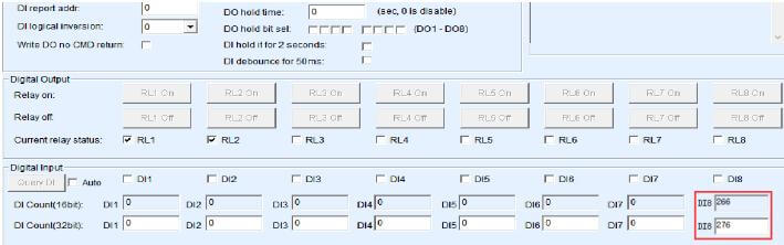
DI count read in the IO controller dialog (Source: Valtoris Hardware Manual)
Deploying a hardware pulse counter requires zero PLC ladder logic programming. For passive dry contact pulse meters, simply wire the meter directly across the DI and GND terminals on the Valtoris module to establish the physical connection.
Because a 32-bit number is too large to fit into a single standard Modbus register, compliant edge I/O modules automatically split the cumulative total across two consecutive 16-bit Holding Registers.
To read the exact pulse count, your SCADA system simply reads these addresses using Modbus Function Code 03 (Read Holding Registers):
| Terminal | Modbus Address (Dec) | Register Data Type | Description |
|---|---|---|---|
| DI 1 | 40257 (0x0100 Hex) | 16-bit Unsigned INT | Pulse Count (High Word): The upper 16 bits of the cumulative total. |
| DI 1 | 40258 (0x0101 Hex) | 16-bit Unsigned INT | Pulse Count (Low Word): The lower 16 bits of the cumulative total. |
// SCADA Integration Note:
In your SCADA software (Ignition, Kepware, etc.) set the tag data type to 32-bit Unsigned Integer (DWord) and address 40257. The software will automatically combine the High and Low words to show the total absolute flow.

Troubleshooting Tip: If the SCADA displays an unusually large or random astronomical number, simply swap the Word Order / Endianness (e.g., Big-Endian to Little-Endian) in your SCADA driver settings.
Stop Losing Data. Start Counting at the Edge.
The Valtoris Remote I/O Series is built for absolute data integrity. Featuring native 32-bit hardware counters on every DI channel, built-in 10ms debounce filters, and built-in NVRAM for power-loss recovery, it ensures your SCADA totals are perfectly accurate, every time.
Frequently Asked Questions (FAQ)
Should I use a dedicated edge node or a high speed counter module for my PLC?
What happens when a 32-bit pulse counter reaches its maximum limit?
How do I manually reset the pulse counter to zero for a new batch process?
32bit DI count save parameter to 0, which restarts the count for the next batch.